1
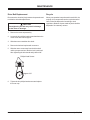
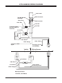
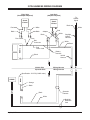
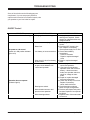
April 1, 2005
Lit. No. 94431
LOW PROFILE TAILGATE
SPREADERS
Owner’s Manual
CAUTION
Read this manual before installing or operating
the spreader.
This manual supersedes all editions with an earlier date.
This manual is for FISHER® Low Profile Spreaders with serial numbers
Model 1000 - (10003 - )
Model 2000 - (20364 - )
TABLE OF CONTENTS
PREFACE .................................................................................................................................. 1
SAFETY INFORMATION ............................................................................................................. 2
Before You Begin ................................................................................................................... 2
Torque Chart .......................................................................................................................... 3
LOADING.................................................................................................................................... 6
Certification ........................................................................................................................... 6
Approximate Material Weights ............................................................................................... 6
MOUNTING THE SPREADER .................................................................................................... 7
Fixed Mount Spreader ........................................................................................................... 7
SWING AWAY® Spreader ....................................................................................................... 8
Receiver Mount Spreader ...................................................................................................... 8
OPERATING THE SPREADER .................................................................................................. 9
Driving and Spreading on Snow and Ice ................................................................................. 9
Accessory Circuit................................................................................................................... 9
Spreader Control ................................................................................................................. 10
ON/OFF Control (Early Style) ............................................................................................... 10
Starting and Stopping the Motor ........................................................................................... 10
ON/OFF Control (Late Style) ................................................................................................ 11
Starting the Motor................................................................................................................. 11
Blast Position ...................................................................................................................... 11
Stopping the Motor .............................................................................................................. 11
Variable Speed (PWM) Control ............................................................................................ 12
Starting the Motor with Variable Speed (PWM) Control......................................................... 12
Stopping the Motor with Variable Speed (PWM) Control....................................................... 12
REMOVING THE SPREADER .................................................................................................. 13
Removing the Fixed Mount Spreader ................................................................................... 13
Removing the Fixed Mount Brackets .................................................................................... 13
Removing the Receiver Mount Spreader .............................................................................. 13
Removing the SWING AWAY Spreader ................................................................................ 13
Removing the SWING AWAY Top Brackets .......................................................................... 13
Removing the SWING AWAY Base Plates ............................................................................ 13
MAINTENANCE ........................................................................................................................ 14
Cleaning .............................................................................................................................. 14
Preseason Check ................................................................................................................14
Postseason Maintenance .................................................................................................... 14
Drive Belt Replacement ....................................................................................................... 15
Recycle................................................................................................................................ 15
Bearing and Set Screw Maintenance ................................................................................... 16
4 PIN HARNESS WIRING DIAGRAM ........................................................................................ 17
2 PIN HARNESS WIRING DIAGRAM ........................................................................................ 18
TROUBLESHOOTING .............................................................................................................. 19
ON/OFF Control................................................................................................................... 19
Mechanical Problems - Variable Speed (PWM) and ON/OFF Control .................................. 20
Early Production - 2 Pin Harness ......................................................................................... 21
April 1, 2005
24
ii
Lit. No. 94430/94431
PREFACE
This manual has been prepared to acquaint you with the
safety information, operation and maintenance of your
new Low Profile tailgate spreader. Please read this
manual carefully and follow all recommendations. This
will help ensure profitable and trouble-free operation of
your spreader. Keep this manual accessible. It is a
handy reference in case minor service is required.
Lit. No. 94430/94431
When service is necessary, bring your spreader to your
local outlet. They know your spreader best and are
interested in your complete satisfaction.
NOTE: This spreader is designed to spread snow
and ice control materials only. Do not use it for
purposes other than those specified in this manual.
1
April 1, 2005
SAFETY INFORMATION
WARNING
WARNING
Indicates a potentially hazardous situation that,
if not avoided, could result in death or
personal injury.
Overloading could result in an accident or
damage. Do not exceed GVWR or GAWR
ratings as found on the driver-side vehicle door
cornerpost. See Loading Section to determine
maximum volumes of spreading material.
CAUTION
Indicates a situation that, if not avoided, could
result in damage to product or property.
WARNING
Do not install the control for this product in the
deployment path of an air bag. Refer to vehicle
manufacturer’s manual for air bag deployment
area(s).
NOTE: Identifies tips, helpful hints and
maintenance information the owner/operator
should know.
CAUTION
Before You Begin
If rear directional, CHMSL light or brake
stoplights are obstructed by the spreader, the
lights shall be relocated, or auxiliary
directional or brake stoplights shall be
installed.
Park the vehicle on a level surface, place shift lever in
PARK or NEUTRAL and set the parking brake.
WARNING
• Driver to keep bystanders minimum of 25 feet
away from operating spreader.
CAUTION
• Do not operate a spreader in need of
maintenance.
• Before working with the spreader, secure all
loose-fitting clothing and unrestrained hair.
• Before operating the spreader, reassemble
any parts or hardware removed for cleaning
or adjusting.
• Before operating the spreader, verify all
safety guards are in place.
• Before servicing the spreader, wait for
conveyor or spinner to stop, then lock out
power.
• Before operating the spreader, remove
materials such as cleaning rags, brushes,
and hand tools from the spreader.
• Do not climb into or ride on spreader.
• Before operating the spreader, read the
owner’s manual.
• While operating the spreader, use auxiliary
warning lights, except when prohibited by
law.
• Tighten all fasteners according to the Torque
Chart. Refer to Torque Chart for the
recommended torque values.
April 1, 2005
2
Lit. No. 94430/94431
SAFETY INFORMATION
Torque Chart
CAUTION
Disconnect electric power at spreader
electrical wiring harness connection and tag
out if required before servicing or performing
maintenance.
CAUTION
Read instructions before assembling. Fasteners
should be finger tight until instructed to tighten
according to the torque chart. Use standard
methods and practices when attaching
spreader, including proper personal protective
safety equipment.
CAUTION
Do not leave unused material in hopper.
Material can freeze or solidify, causing unit to
not work properly. Empty and clean hopper
after each use.
Recommended Fastener Torque
Chart (Ft.-Lb.)
NOTE: Maintain proper belt tension for correct belt
functioning.
NOTE: Lubricate grease fittings after each use. Use
a good quality multi-purpose grease.
NOTE: Airborne noise emission during use is
below 70 dB(A) for the spreader operator.
Size
SAE
Grade 2
SAE
Grade 5
1/4-20
5/16-18
3/8-16
3/8-24
7/16-14
1/2-13
9/16-12
5/8-11
3/4-10
7/8-9
1-8
6
11
19
24
30
45
66
93
150
150
220
9
18
31
46
50
75
110
150
250
378
583
SAE
Grade 8
13
28
46
68
75
115
165
225
370
591
893
Metric Grade 8.8 (Ft.-Lb.)
Size
Torque
Size
M6
M8
M 10
7
17
35
M 12
M 14
M 16
Torque
60
95
155
These torque values apply to fasteners
except those noted in the instruction.
Lit. No. 94430/94431
3
April 1, 2005
SAFETY INFORMATION
Please become familiar with the Warning
and Caution Labels on the spreader!
Caution Label
CAUTION
DO NOT SWING SPREADER
WITH MATERIAL IN THE HOPPER
P2110
Caution Label
Located on both sides
SWING AWAY® mount only
TION
CAU
WAR
NING
CAU
TION
Warning/Caution Label
Located on both sides
Warning/Caution Label
WARNING
CAUTION
• DO NOT EXCEED GVWR OR GAWR WITH SPREADER AND LOAD.
• TURN SPREADER OFF BEFORE FILLING, ADJUSTING, OR CLEANING.
• BYSTANDERS TO STAY A MINIMUM OF 25 FEET AWAY FROM
OPERATING SPREADER.
• DO NOT CLIMB INTO OR RIDE ON SPREADER.
• KEEP HANDS, FEET, CLOTHING AWAY FROM MOVING CONVEYOR
AND SPINNER.
• READ OWNER'S MANUAL BEFORE OPERATING OR SERVICING
SPREADER.
• EMPTY AND CLEAN SPREADER AFTER EACH USE.
68584
April 1, 2005
4
Lit. No. 94430/94431
SAFETY INFORMATION
Warning Label
WARNING
DO NOT EXCEED HITCH MANUFACTURER RATINGS.
DO NOT EXCEED GVWR OR GAWR WITH SPREADER AND LOAD.
94426
Warning Label
located on both sides
of receiver mount only.
WAR
N
ING
CAU
TION
Warning/Caution Label
Located on both sides
Warning/Caution Label
WARNING
CAUTION
• DO NOT EXCEED GVWR OR GAWR WITH SPREADER AND LOAD.
• TURN SPREADER OFF BEFORE FILLING, ADJUSTING, OR CLEANING.
• BYSTANDERS TO STAY A MINIMUM OF 25 FEET AWAY FROM
OPERATING SPREADER.
• DO NOT CLIMB INTO OR RIDE ON SPREADER.
• KEEP HANDS, FEET, CLOTHING AWAY FROM MOVING CONVEYOR
AND SPINNER.
• READ OWNER'S MANUAL BEFORE OPERATING OR SERVICING
SPREADER.
• EMPTY AND CLEAN SPREADER AFTER EACH USE.
68584
Lit. No. 94430/94431
5
April 1, 2005
LOADING
This manual covers vehicles which have been
recommended for carrying the spreader. Please see
your local dealer for proper vehicle applications.
WARNING
Overloading could result in an accident or
damage. Do not exceed GVWR or GAWR
ratings as found on the driver-side vehicle door
cornerpost.
Certification
WARNING
NOTE: If spreader and ice control material loading
is in doubt weigh vehicle for compliance with
vehicle ratings.
New untitled vehicle installation of a spreader
requires National Highway Traffic Safety
Administration altered vehicle certification
labeling. Installer to verify that struck load of snow
or ice control material does not exceed GVWR or
GAWR rating label and complies with FMVSS.
NOTE: Use only dry, free-flowing granular
materials with this spreader. Damp or wet ice
control materials and other products may not
spread properly.
Approximate Material Weights
CAUTION
Read and adhere to manufacturer’s ice control
package labeling including Material Safety
Data Sheet requirements.
Model 1000
Cu. Ft. LB
Model 2000
Cu. Ft. LB
8.0
320
10.6
424
5.9
236
7.2
288
3.1
124
3.1
124
Salt = 40 lb./ft.³ (avg.)
Very Coarse = 35 lb./ft.³
Coarse = 45 lb./ft.³
Fine = 50 lb/ft.³
Plus Approximate Base Unit Weights of 154 Lbs. for 1000 Unit and 161 Lbs. for 2000 Unit, Including Mount.
April 1, 2005
6
Lit. No. 94430/94431
MOUNTING THE SPREADER
Fixed Mount Spreader
NOTE: The spreader shall be installed according to
instructions supplied. Your local outlet is trained to
provide this service and service your spreader with
factory original parts.
1. Install the left and right top brackets to the truck
bed rail with one 1/2" cap screw, one 1/2" flat
washer and one 1/2" locknut. Attach the other hole
in the top bracket to the bed rail with one 1/2" cap
screw and one 1/2" locknut.
WARN
ING
CAUT
ION
2. Place the spreader on the bumper and line up the
holes in the bottom feet with the holes in the
bumper.
3. Attach the spreader to the top brackets using two
3/8" cap screws and two 3/8" locknuts per side.
4. Attach the spreader to the bumper of the truck
using one 3/8" cap screw, one 3/8" flat washer and
one 3/8" locknut per side.
CAUTION
During removal or mounting, securely grip
spreader to avoid dropping.
5. Plug the spreader harness into the vehicle harness.
Lit. No. 94430/94431
7
April 1, 2005
MOUNTING THE SPREADER
1. Fasten the left and right top brackets along with any
shims to the truck bed rail with two 1/2" cap
screws, two 1/2" flat washers and two 1/2" locknuts
per bracket. Install the two 5/16" cap screws and
locknuts to the side of the top brackets.
SWING AWAY® Spreader
2. Place the left and right base plates on the bumper
of the truck and line up with the holes in the
bumper.
CAU
TION
ER
SPREAD
SWING
HOPPER
THE
DO NOT
AL IN
MATERI
WITH
3. Attach the base plates to the bumper using three
3/8" cap screws, three 3/8" plain washers, any
shims and three 3/8" locknuts per side.
WARN
ING
CAUT
ION
4. Place the spreader on the base plates and insert
the hinge pins. Secure the hinge side by installing
one 1/4" cap screw and 1/4" locknut through the
hole in the base plate boss and hinge pin.
5. Install hitch pin clip through the base plate boss
and the removable hinge pin.
CAUTION
During removal or mounting, securely grip
spreader to avoid dropping.
6. Plug the spreader harness into the vehicle harness.
7. Plug the stoplight cord into the vehicle stoplight
harness.
NOTE: The spreader shall be installed according to
instructions supplied. Your local outlet is trained to
provide this service and service your spreader with
factory original parts.
Receiver Mount Spreader
CAUTION
During removal or mounting, securely grip
spreader to avoid dropping.
NOTE: The spreader shall be installed according to
instructions supplied. Your local outlet is trained to
provide this service and service your spreader with
factory original parts.
1. Attach the spreader to the receiver mount with six
3/8"-16 x 1" cap screws.
WARN
ING
CAUT
ION
2. Insert the assembled unit into the receiver hitch and
secure with pin (not included).
3. Plug the spreader harness into the vehicle harness.
April 1, 2005
8
Lit. No. 94430/94431
OPERATING THE SPREADER
Driving and Spreading on Snow and Ice
Accessory Circuit
The yellow wire in the vehicle harness is provided for
accessory use of 12 amps or less.
CAUTION
Drinking and then driving or spreading is very
dangerous. Your reflex, perceptions,
attentiveness and judgement can be affected
by even a small amount of alcohol. You can
have a serious or even fatal collision if you
drive after drinking. Please do not drink then
drive or spread ice control materials.
Follow your vehicle owner’s manual instructions for
driving in snow and ice conditions. Remember when
you drive on snow or ice, your wheels will not get good
traction. You cannot accelerate as quickly, turning is
more difficult and you will need longer braking distance.
Wet and hard packed snow or ice offers the worst tire
traction. It is very easy to lose control. You will have
difficulty accelerating. If you do get moving, you may
have poor steering and difficult braking which can cause
you to slide out of control.
Here are some tips for driving in these conditions.
• Drive defensively.
• Do not drink, then drive or spread ice control
materials
• Spread or drive only when you have good visibility
for operating a vehicle.
• If you cannot see well due to snow or icy
conditions, you will need to slow down and keep
more space between you and other vehicles.
• Slow down, especially on higher speed roads. Your
headlamps can light up only so much road ahead.
• If you are tired, pull off in a safe place and rest.
• Spreader size reduces driver visibility to the rear of
the vehicle due to spreader size and location. We
recommend OSHA compliant backup alarm for all
governed employers.
• Keep your windshield and all glass on your vehicle
clean to see around you.
• Dress properly for the weather. Wear layers of
clothing, as you get warm you can take off layers.
Lit. No. 94430/94431
9
April 1, 2005
OPERATING THE SPREADER
Spreader Control
Starting and Stopping the Motor
There are two control options. They are the ON/OFF
Control and the Variable Speed (PWM) Control.
WARNING
Before starting the spreader, the driver shall
verify all bystanders are a minimum of 25 feet
away from operating spreader.
CAUTION
If the unit is equipped with a SWING AWAY®
mount. Do not operate the spreader or the
vehicle without securing the hinge pin in the
base plate.
1. Move the power switch to the on position to start
the motor. Motor will start immediately. The power
switch will remain in this position. The power
switch works as emergency stop when required.
ON/OFF Control (Early Style)
2. Move the power switch to the OFF position to stop
the motor. The power switch will remain in this
position.
1 (Emergency Stop)
RESET
ON
OFF
POWER
NOTE: The truck ignition must be on to start the
spreader.
15
NOTE: If the truck ignition is turned off while the
spreader is running, the motor will stop.
2
If there are problems while operating the spreader, refer
to the Troubleshooting section in this manual.
1. Power Switch - used to start and stop the spinner.
The power switch OFF position operates as
emergency stop when required.
NOTE: Always place the cover on the hopper to
prevent moisture buildup. Do not let the spreader
sit idle with material in the hopper for an extended
period of time. This can cause the material to
compact and reduce or stop the flow of material.
2. Circuit Breaker - used to reset the control should an
electrical fault occur.
CAUTION
Do not swing spreader with material in the
hopper.
April 1, 2005
10
Lit. No. 94430/94431
OPERATING THE SPREADER
ON/OFF Control (Late Style)
Stopping the Motor
1. Set the power switch to the OFF position to stop the
motor. The power switch will remain in this position.
The power switch OFF position operates as
emergency stop when required.
ON
OFF
BLAST
NOTE: Always place the cover on the hopper to
prevent moisture buildup. Do not let the spreader
sit idle with material in the hopper for an extended
period of time. This can cause the material to
compact and reduce or stop the flow of material.
SPINNER
On/Off Control Switch
Spinner Indicator Light
Used to start and stop
Illuminated light Indicates
the spinner.
power to the motor.
(Emergency Stop-OFF Position)
CAUTION
Starting the Motor
Do not swing spreader with material in the
hopper.
WARNING
NOTE: The truck ignition must be on to start the
spreader.
Before starting the spreader, the driver shall
verify all bystanders are a minimum of 25 feet
away from operating spreader.
NOTE: If the truck ignition is turned off while the
spreader is running, the motor will stop.
1. Set the power switch to the ON position to start the
motor. The motor will start immediately. The power
switch will remain in this position.
Blast Position
Move and hold the power switch to the BLAST position
for as long as momentary operation is needed. When
released, the switch will automatically return to the OFF
position and stop the motor.
Lit. No. 94430/94431
11
April 1, 2005
OPERATING THE SPREADER
Variable Speed (PWM) Control
Stopping the Motor with Variable Speed
(PWM) Control
5
4
7
3
8
2
START
BLAST
1. Set the power switch to the OFF position to stop
the motor. The power switch will remain in this
position. This is also the emergency stop position.
6
NOTE: Always place the cover on the hopper to
prevent moisture buildup. Do not let the spreader
sit idle with material in the hopper for an extended
period of time. This can cause the material to
compact and reduce or stop the flow of the
material.
9
1
ON
MIN
MAX
OFF
SPEED
SPINNER
1 (Emergency StopOFF Position)
3
2
1. Power Switch - used to start and stop the spinner.
The power OFF position switch operates as
emergency stop when required.
CAUTION
Do not swing spreader with material in the
hopper.
2. Speed Dial - used to change the speed of the
spinner.
NOTE: The truck ignition must be on to start the
spreader.
3. Indicator Lights - indicate whether the spinner is in
motion. Left light is red and indicates a fault. Right
light is green and indicates power is on.
NOTE: If the truck ignition is turned off while the
spreader is running, the motor will stop.
Starting the Motor with Variable Speed
(PWM) Control
WARNING
Before starting the spreader, the driver shall
verify all bystanders are a minimum of 25 feet
away from operating spreader.
1. To start the spreader motor, press the power switch
to the START/BLAST position and release. This is a
momentary position and the power switch will
automatically return to the ON position when
released. The spreader will operate at the speed
selected on the speed dial.
2. To increase the speed of the spinner rotate the
speed dial clockwise.
3. To decrease the speed of the spinner rotate the
speed dial counterclockwise.
April 1, 2005
12
Lit. No. 94430/94431
REMOVING THE SPREADER
NOTE: Empty the hopper before removing the
spreader.
CAUTION
During removal or mounting, securely grip
spreader to avoid dropping.
Removing the SWING AWAY® Spreader
NOTE: Empty the hopper before removing the
spreader.
1. Unplug the spreader and stoplight (if equipped).
2. Remove the hitch pin from the latch side hinge pin.
Removing the Fixed Mount Spreader
3. Remove the 1/4" cap screw and locknut from the
hinged side hinge pin.
1. Unplug the spreader and stoplight (if equipped).
4. Use an additional person to support the unit and
remove both hinge pins.
2. Remove the two 3/8" cap screws, washers, and
locknuts that fasten the spreader to the bumper of
the vehicle.
5. Remove the spreader from the vehicle and stand in
an upright position. This may require additional
support.
3. Use an additional person or clamps to support the
unit and then remove the four 3/8" cap screws and
locknuts that fasten the spreader to the top
brackets.
Removing the SWING AWAY Top Brackets
4. Remove the spreader from the vehicle and stand in
an upright position. This may require additional
support.
1. Remove the two 1/2" cap screws, washers and
locknuts that fasten the top bracket to the bed rail.
Removing the Fixed Mount Brackets
2. Remove the two 5/16" cap screws and locknuts that
fasten the top bracket to the side of the bed rail.
1. Remove the two 1/2" cap screws, washers and
locknuts that fasten the top bracket to the bed rail.
3. Mark the location of any shims to aid in
reinstallation.
2. Remove the two 5/16" cap screws, washers and
locknuts that fasten the top brackets the side of the
bed rail.
4. Package the brackets with all hardware and store
with the unit.
Removing the SWING AWAY Base Plates
3. Package the brackets with all hardware and store
with the unit.
1. Remove the three 3/8" cap screws, washers,
locknuts and any shims that fasten the base plate
to the bumper.
NOTE: Empty the hopper before removing the
spreader.
2. Mark the location of the shims to aid in
reinstallation.
Removing the Receiver Mount Spreader
3. Package the base plates with all hardware and
store with the unit.
1. Unplug the spreader.
2. Remove the pin from the receiver hitch.
3. Remove the spreader from the vehicle and stand in
an upright position. This may require additional
support.
Lit. No. 94430/94431
13
April 1, 2005
MAINTENANCE
4. If bearings pass inspection be sure to thoroughly
grease them with a good quality multi-purpose
grease. See Bearing Maintenance in this section.
CAUTION
Disconnect electric power at spreader
electrical wiring harness connection and tag
out if required before servicing or performing
maintenance.
5. Verify all drive sprocket set screws are tight. Verify
that all other fasteners are tight. Refer to the Torque
Chart in the safety section of this manual.
Cleaning
6. Check the condition of the motor cap assembly
seal. This seal is very important to the
dependability of your unit. Replace the seal if
needed.
After every use, clean the spreader, but first disconnect
the electrical plug located between the spreader and the
truck. The spreader can be cleaned using tap water or
a high pressure washer. A long handle brush can be
used to aid cleaning.
7. Check the condition of the spinner disk. If the
vanes are excessively worn the unit may not spread
as intended. Replace the spinner if necessary.
CAUTION
• Do not operate a spreader in need of
maintenance.
8. Replace the motor cap assembly and locknuts.
• Before operating the spreader, reassemble
any parts or hardware removed for cleaning
or adjusting.
9. Verify vehicle stoplights and spreader center high
mounted stoplight are working properly.
Postseason Maintenance
• Before operating the spreader, remove
materials such as cleaning rags, brushes,
and hand tools from the spreader.
Before storing the unit for the off season, taking a few
minutes to do the following will extend the service life of
your spreader.
• Empty and clean spreader after every use.
Material can freeze or solidify causing unit to
not work properly.
1. Thoroughly clean the unit inside and out.
Preseason Check
2. Apply dielectric grease to all electrical connections
to prevent corrosion.
Before the unit is placed in service for the ice control
season make sure that it is in top working condition.
Here are some tips for getting your spreader ready.
3. Grease the drive shaft bearings.
4. Oil or paint all bare metal surfaces.
Remove the motor cap assembly and inspect the
following:
5. Place the lid on the hopper body of the unit and
secure the latch.
1. Check the condition of the drive belt. Any cracks or
damaged teeth indicate the need for a new belt.
See Drive Belt Replacement in this section.
6. Store the unit in an upright position; stabilize it with
supports if necessary. If the unit is stored outdoors,
cover the unit and place it on blocks to eliminate
ground moisture.
2. Check the motor connection terminals for damage
or corrosion. Clean or replace as necessary and
coat with dielectric grease.
3. Check the condition of the drive shaft bearings by
first removing the drive belt. To remove the drive belt
see Drive Belt Replacement in this section. With
the drive belt removed spin the drive shaft by hand.
Any excess noise or roughness in either the top or
the bottom bearing may indicate bearing failure.
April 1, 2005
14
Lit. No. 94430/94431
MAINTENANCE
Drive Belt Replacement
Recycle
Disconnect the electrical plug between the spreader and
truck before drive belt replacement.
When your spreader has performed its useful life, the
majority of its components can be recycled as steel.
Gear oil shall be disposed of according to local
regulations. Balance of parts made of plastic shall be
disposed of in customary manner.
CAUTION
Overtightening the belt may result in damage
to the motor or bearings.
1. Remove the motor cap assembly.
2. Loosen the four phillips head screws that fasten the
motor mount to the drive support.
3. Slide the motor toward the drive shaft.
4. Remove the belt and replace with a new one.
5. Slide the motor mount away from the drive shaft
until the proper tension of the drive belt is achieved.
After tightening the belt should easily deflect 3/8".
Phillips Head Screws
Approx. 3/8”
6. Tighten the four phillips head screws and replace
the motor cap.
Lit. No. 94430/94431
15
April 1, 2005
MAINTENANCE
Bearing and Set Screw Maintenance
Disconnect the electrical plug between the spreader and
the truck before performing any maintenance.
1. Tighten all set screws shown after every 60 hours of
use.
2. Grease the top and bottom drive shaft bearings as
shown. Due to the harsh environment of the bottom
bearing it will require more care than the top
bearing.
Top Bearing
Set Screw
Motor Pulley
Set Screw
Shaft Pulley
Set Screw
Top Bearing:
Grease after every
60 hours of use.
Use a good quality
multi-purpose grease.
Auger
Set Screw
Spinner
Set Screw
Bottom Bearing:
Grease after every
8 hours of use.
Use a good quality
multi-purpose grease.
Bottom Bearing
Set Screw
April 1, 2005
16
Lit. No. 94430/94431
4 PIN HARNESS WIRING DIAGRAM
Cab Control
White Connector
Two-Way Molded
Connector
6 Amp Fuse
Red Connector
14 Ga. Red
8 Ga. Red
To Vehicle Ignition
(Accessory Wire or
Fuse Box)
8 Ga. Red
30 Amp Fuse
14 Ga. Black
_
Battery
+
10 Ga. Red
8 Ga. Black
14 Ga. Yellow
14 Ga. Orange
To Vehicle CHMSL
Signal
Accessory Circuit
(12 AMP MAX)
Vehicle
Wiring Harness
Spreader
Wiring Harness
Motor
CHMSL
Assy
B A
14 Ga. Black
8 Ga. Red
14 Ga. Yellow
Accessory Circuit
8 Ga. Black
14 Ga. Orange
Motor Specification:
12 Volt DC, .56 kW Motor
Lit. No. 94430/94431
17
April 1, 2005
2 PIN HARNESS WIRING DIAGRAM
Early Style
(No Adapter Required)
Late Style
(Adapter Required)
Speed
Control
To
CHMSL
Signal
Speed
Control
Black
Red
White
Black
Black
White
Adaptor
Black
Fuse holder
Red
White
Stoplight
Vehicle
Harness
Fuse
Butt
Connector
White
+
Black
Battery
Red
Power Lead
Battery
Harness
Vehicle
Harness
_
Black
Vehicle Side
Spreader Side
Wiring Harness
Wiring Harness
CHMSL
Motor
Specification: 12V DC (0.4kW motor)
Orange
Black
Spreader
Harness
Black
White
Stoplight
Extension
Cord
April 1, 2005
18
Lit. No. 94430/94431
TROUBLESHOOTING
Some of the solutions on the following page are
complicated. If you are not properly trained or
experienced in electrical or mechanical repairs, take
you spreader to your local outlet for repairs.
ON/OFF Control
PROBLEM
Ice control material not flowing
POSSIBLE CAUSE
1. Bridging of material in hopper.
1. Control connector plug is loose.
2. Blown fuse.
No power to cab control
(Switch is in ON position indicator
light not lit)
3. Low battery or loose connection.
4. Open circuit in wire from battery
to cab control.
1. Wire harness is damaged or has
an open circuit between cab
control and spreader.
Spreader does not operate
(Indicator light lit)
2. Bearings are seized.
3. Motor brushes are worn and
prevent motor operation.
4. Motor bearings seized.
Lit. No. 94430/94431
19
SUGGESTED SOLUTION
1. Unplug the spreader harness
and tag out if required. Check
hopper for material and free any
bridged material.
1. Check plug connection at cab
control.
2. Check the SFE 6 amp in-line
fuse. Replace if necessary.
Check power supply for 12 VDC.
3. Check vehicle battery
connections.
- Clean off corrosion
- Repair or replace damaged
wires
4. Repair or replace damaged
wires.
1a. Check plug connections at cab
control and spreader.
1b. Check wire connections at
spreader motor and at vehicle
battery – disconnect motor
leads, turn spreader switch on,
check for voltage at motor
leads.
1c. Repair or replace damaged
wires and connectors
1d. Check the 30-amp in-line fuse.
Replace if necessary.
Motor shaft should turn.
2. Check bearings on spinner
shaft, conveyor, and gearbox.
3. Remove and inspect both motor
brushes. Replace if worn (Brush
kit 65241).
4. Replace motor if the motor shaft
will not turn.
April 1, 2005
TROUBLESHOOTING
Mechanical Problems - Variable Speed (PWM) and ON/OFF Control
PROBLEM
Ice control material not flowing
POSSIBLE CAUSE
1. Bridging of material in hopper.
1. Drive belt is loose or damaged.
2. Motor pulley not secured to
motor shaft.
Spinner does not turn
(Spreader motor is running)
3. Spinner pulley is not secured to
the spinner shaft.
4. Spinner shaft bearings are dry or
seized.
1. Drive belt is loose or damaged.
2. Pulley is not secured to the
spinner shaft.
3. Pulley is not secured to the
gearbox shaft.
4. Gearbox is damaged.
Conveyor belt not moving
(Spinner is turning)
5. Conveyor rollers are not secured
to the shafts.
6. Conveyor belt is loose or
damaged.
7. Conveyor belt is not aligned.
8. Conveyor belt shaft bearings are
seized or otherwise damaged.
Material in hopper does not flow
(Conveyor belt and spinner are
moving)
1. Feedgate is closed.
2. Obstruction in hopper.
Spread pattern not optimum
April 1, 2005
1. Deflector out of adjustment.
20
SUGGESTED SOULUTION
1. Unplug the spreader harness
and tag out if required. Check
hopper for material and free any
bridged material.
1. Unplug the spreader harness
and tag out if required.
Reconnect after solution.
2. Adjust belt tension. Replace belt
if damaged.
3. Tighten pulley set screw.
Replace pulley if damaged.
4. Replace cap screw and nut if
missing or damaged. Replace
pulley if damaged.
1. Unplug the spreader harness
and tag out if required.
Reconnect after solution.
2. Adjust belt tension. Replace belt
if damaged.
3. Tighten pulley set screw.
Replace pulley if damaged
4. Replace damaged or missing
key. Replace pulley if damaged.
5. Replace gearbox if output shaft
does not turn when input shaft
turns.
6. Replace missing cap screws and
nuts. Replace shafts or rollers if
damaged.
7. Adjust belt tension. Replace belt
if damaged.
8. Align belt to ride centered on
rollers.
9. Grease or replace bearings.
1. Unplug the spreader harness
and tag out if required.
Reconnect after solution.
2. Open feedgate fully, then adjust
to desired opening size.
3. Remove obstruction.
1. Unplug the spreader harness
and tag out if required.
Reconnect after solution.
2. Change deflector adjustment to
suit desired pattern. (See
“Operating the Spreader” in this
manual.)
Lit. No. 94430/94431
TROUBLESHOOTING
Early Production - 2 Pin Harness
PROBLEM
Ice control material not flowing
POSSIBLE CAUSE
Bridging of material in hopper
Spreader Control power switch is in the
OFF position
Spreader Control circuit breaker is
tripped (ON/OFF control only)
Spinner does not spin – No power to
the spreader control
Battery lead in-line fuse is blown
Battery connection is poor
Battery wiring harness is damaged
Spinner, auger, or driveshaft is
jammed or overloaded
Spinner shaft bearings are damaged
Spinner does not spin – The motor is
not turning and 12V DC power is
present at the red wire to red wire
connection located near the rear of the
spreader control
Motor is damaged
Spreader Control is damaged
Wiring harness is damaged
Drive belt is loose or broken
Spinner does not spin when load is
applied – The motor is turning
Drive pulley is loose
Lit. No. 94430/94431
21
SUGGESTED SOLUTION
Unplug the spreader harness and tag
out if required. Check the hopper for
material and free any bridged material.
Set the power switch to the ON
position.
Set the power switch to the OFF
position. Reset the circuit breaker and
set the power switch to the ON
position.
Change the fuse and inspect for short
circuits.
Clean or replace ring terminal. Coat
with dielectric grease.
Repair or replace battery wiring
harness as required.
Unplug the spreader harness and tag
out if required. Turn the spinner by
hand. If the shaft will not turn freely by
hand, check for any obstructions or
frozen material. Clear all obstructions.
Unplug the spreader harness and tag
out if required. Remove the drive belt
and spin the spinner by hand. If the
shaft will not turn freely by hand, check
for obstructions. If no obstructions
exist, lubricate or replace the spinner
bearings.
Unplug the spreader harness and tag
out if required. Turn the spinner by
hand. If the shaft will turn freely and
the belt and pulleys are in working
order, reconnect the spreader harness
and check for 12V DC at the orange
wire to white wire connection located
near the motor. If the motor has 12V
DC, the problem is in the motor.
Replace the motor.
Check for 12V DC at the white wire to
white wire connection near the back of
the spreader control. If the control
does not have power, the problem is in
the control. Replace the control.
Check for 12V DC at the white wire to
white wire connection near the back of
the spreader control. If the control has
12V DC, check for 12V DC at the white
wire to orange wire connection located
near the motor. If the motor does not
have power, then the problem is in the
spreader wiring harness. Repair or
replace the wiring harness as
necessary.
Unplug the spreader harness and tag
out if required. Remove the motor cap
and check for a loose or broken drive
belt. Tighten or replace the belt as
necessary.
Unplug the spreader harness and tag
out if required. Remove the motor cap
and verify motor and drive pulley set
screws are tight.
April 1, 2005
FISHER ENGINEERING
P.O. BOX 529
ROCKLAND, MAINE 04841
A DIVISION OF DOUGLAS DYNAMICS, L.L.C.
Copyright © 2005 Douglas Dynamics, L.L.C. All rights reserved. This material may not be reproduced or copied, in whole or in part, in any
printed, mechanical, electronic, film or other distribution and storage media, without the written consent of Fisher Engineering. Authorization to
photocopy items for internal or personal use by Fisher Engineering outlets or spreader owner is granted.
Fisher Engineering reserves the right its product improvement policy to change construction or design details and furnish equipment when so
altered without reference to illustrations or specifications used. Fisher Engineering and the vehicle manufacturer may require and/or recommend
optional equipment for spreaders. Do not exceed vehicle ratings with a spreader. This product is manufactured under the following US patent:
5,375,773. Fisher Engineering offers a limited warranty for all spreaders and accessories. See separately printed page for this important
information. The following are registered (®) trademarks of Douglas Dynamics, L.L.C.: WESTERN® and SWING AWAY®.
Printed in U.S.A.
April 1, 2005
Lit. No. 94431