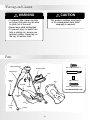
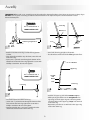
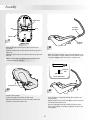
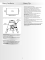
1
Cradle Swing
Cradle
Swing
Model Number: 79595, 79596
Please keep this instruction sheet for future reference, as it contains important information.
Adult assembly is required.
Tools needed for assembly: Phillips Screwdriver and Adjustable Wrench (both not included).
Requires three “D” (LR20) alkaline batteries for operation (not included).
Maximum Weight Limit: 24 lbs. (10.9 kg.)
The maximum weight limit for this product is 24 lbs.
IMPORTANT! If your child weighs less than 24 lbs., but is really active and appears to be
able to climb out of the swing, immediately discontinue its use.
ib
Discover what ’s poss
le …
™
ishe
f
.
w
ww
r-
e.c
c
i
r
p
om
Warnings and Caution
WARNING
CAUTION
• To prevent falls, never use with
an active child who may be able
to climb out of the seat.
• Never leave child unattended.
• To prevent injury or death from
falls or sliding out, always use
restraint system. Never rely on
the tray to restrain child.
This product contains small parts
in its unassembled state. Adult
assembly is required.
Parts
Motorized Frame
#8 x 1/2" Pointed Screw - 2
Activity Toy Bar
2 Upper Legs
Tray
2 Elbow
Feet
M4 x 31.5 mm Bolt - 2
Pad
M4 Lock Nut - 2
Seat Tube
#8 x 3/4" Pointed Screw - 2
Mobile
ALL SHOWN ACTUAL SIZE
Seat Tube
Arm
Seat
2 Lower
Legs
2 Feet
2
Assembly
IMPORTANT! Before each use or assembly, inspect this product for damaged hardware, loose joints, missing parts or sharp edges.
DO NOT use if any parts are missing or broken. Contact Fisher-Price® for replacement parts and instructions if needed.
Never substitute parts.
Lower Leg
#8 x 3/4" Pointed Screw - 2
SHOWN ACTUAL SIZE
Elbow Foot
Lower Leg Long Portion
1
Cup
Side
Down
Foot
Elbow Foot
3
Correct
Incorrect
• Stand each lower leg upright, as illustrated.
• The elbow foot and foot should be flat against the floor.
• Position one of the lower legs so that the long portion
is down.
• Fit an elbow foot, with the cup side down, onto the bend
in the lower leg.
• Insert a #8 3/4" pointed screw through the bottom of the
elbow foot and into the lower leg. Tighten the screw with
a Phillips screwdriver. Do not over-tighten.
Red Dot
Upper Leg
#8 x 1/2" Pointed Screw - 2
Straight
End
Button
SHOWN ACTUAL SIZE
Hole
Lower Leg
Lower Leg
Foot
4
2
• Position an upper leg so that the red dot is upward.
• While pressing the button on the straight end of an
upper leg, insert the upper leg into a lower leg. Make
sure the button on the upper leg “snaps” into the hole
in the lower leg.
• Repeat this procedure to assemble the other upper leg
to the other lower leg.
• Fit a foot onto the end of the lower leg.
• Insert a #8 1/2" pointed screw through the bottom of the
foot and into the lower leg. Tighten the screw with a
Phillips screwdriver. Do not over-tighten.
• Repeat assembly steps 1 and 2 to assemble the other
elbow foot and foot to the other lower leg.
3
Assembly
Hole
Tubes
Motorized
Frame
Battery
Compartment
5
Hole
Feet
Feet
L
• Position the motorized frame so that the battery
compartment is toward you.
• Position the tubes in the motorized frame so that they are
toward the outer edges. The holes in the tubes should be
visible through the notches in the motorized frame.
L
R
7
• Stand the assembly upright. All four feet should be flat upon
the floor. Also, when standing behind the product, check for
an L marking on the left foot and an R marking on the
right foot.
• If the feet are not flat upon the floor, or the left and right feet
have been reversed, simply remove both legs and replace
them on the opposite tube in the motorized frame. Again,
check to be sure all four feet are flat upon the floor.
Motorized Frame
R
Seat
Button
6
Elbow Foot
Hole
Red Dot
Tube
Waist
Belts
• Locate the R and L on the underside of each elbow foot.
The R indicates the right leg. The L indicates the left leg.
• While pressing the upper button on the right leg, fit it
into the tube in the motorized frame. Make sure the
upper button on the right leg “snaps” into the hole in
the tube.
• While pressing the button on the left leg, fit it into the
tube in the motorized frame. Make sure the button on
the left leg “snaps” into the hole in the tube.
• When the legs are assembled correctly to the tubes in the
motorized frame, you should not see the red dots.
Pad
Elastic
Loops
8
4
• Position the seat upright.
Crotch Belt
• Place the pad onto the seat with the
ruffle toward the top of the seat.
• Fold the top of the pad down. Insert the waist belts through
the slots in the pad. Make sure the waist belts are not twisted.
• Insert the two elastic loops on the pad through the holes in
the seat bottom.
• Fold the bottom of the pad up. Insert the crotch belt through
the slot in the pad. Make sure the crotch belt is not twisted.
Assembly
Elastic Loop
Peg
Seat Tube
Arm Hole
Peg
Elastic Loop
9
Seat Tube
Button
Bottom View
11
• While holding the elastic loops in place, turn the seat
face down.
• Hook the elastic loop on the left side onto the peg on the
right side.
• Hook the elastic loop on the right side onto the peg on the
left side.
• While pressing the button on the seat tube, slide the seat
tube arm onto the seat tube. Make sure the button on the
seat tube “snaps“ into the hole in the seat tube arm.
Hint: The elastic loops should cross over each other when
attached correctly to the pegs.
M4 x 31.5 mm Bolt
Rounded
Side
M4 Lock Nut
Shown Actual Size
Fasteners
10
12
• Turn the seat upright.
• Fit the pad edges around the rim of the seat.
• Attach the two fasteners on each side of the pad to the
fasteners on each side of the seat.
• Insert an M4 x 31.5 mm bolt through the seat tube arm
and seat tube.
• Attach an M4 lock nut to the bolt. Make sure the rounded
side of the lock nut faces out.
• Using an adjustable wrench, hold the lock nut in place.
Then using a Phillips screwdriver, tighten the bolt. Do not
over-tighten.
5
Assembly
Toy Bar
Button
Tray
Slot
Mobile
13
Slot
15
• Turn the seat upright.
• Insert the tray tabs into the slots in each side of the seat.
• Insert the ends of the toy bar into the holes in the tray. Press
down on the ends of the toy bar to be sure they are secure.
Seat Tube
Button
14
• Slide the button on the top of the mobile into the slot in
the motorized frame.
Assembly is now complete.
Motorized
Frame Tube
Hole
M4 x 31.5 mm Bolt
Rounded
Side
• Press the button on the
M4 Lock Nut
seat tube and slide the
Shown Actual Size
seat tube into the motorized frame tube. Make sure
the button on the seat tube “snaps” into the larger hole in
the motorized frame tube.
• Insert a M4 x 31.5 mm bolt through smaller hole in the
motorized frame tube and into the seat tube.
• Attach an M4 lock nut to the bolt. Make sure the rounded
side of the lock nut faces out.
• Using an adjustable wrench, hold the lock nut in place.
Then, using a Phillips Screwdriver, tighten the bolt. Do not
over-tighten.
6
Battery Installation
+
1.5V x 3
“D” (LR20)
Battery Tips
• Do not mix old and new batteries.
• Do not mix different types of batteries: alkaline, standard
(carbon-zinc) or rechargeable (nickel-cadmium).
• Remove the batteries during long periods of non-use.
Always remove exhausted batteries from this product.
Battery leakage and corrosion can damage this product.
Dispose of batteries safely.
• Do not dispose of batteries in a fire. The batteries may
expolde or leak.
• Never short-circuit the battery terminals.
• Non-rechargeable batteries are not to be recharged.
• Only batteries of the same or equivalent type as
recommended in the battery installation instructions
are to be used.
• If removable rechargeable batteries are used, they are only
to be charged under adult supervision.
• Rechargeable batteries are to be removed from the product
before they are charged.
• If you use a battery charger, it should be examined regularly
for damage to the cord, plug, enclosure and other parts.
Do not use a damaged battery charger until it has been
properly repaired.
-
SHOWN ACTUAL SIZE
Battery
Compartment
Door
Battery
Compartment
• Using a coin, press the tab on the battery compartment
door and remove it.
• Insert three “D” (LR20) alkaline batteries, as indicated
inside the battery compartment.
Hint: We recommend using alkaline batteries for longer
battery life.
• Replace the battery compartment door.
Hint: If the swinging motion becomes noticeably slower,
remove the batteries and replace them with three, new
“D” (LR20) alkaline batteries. Dispose of exhausted
batteries properly.
7
Cradle and Swing Use
Your Cradle Swing changes from a traditional swing to a
rocking cradle at the push of a button!
To Unfold
IMPORTANT! Before each use or assembly, inspect this product for damaged hardware, loose joints, missing parts or sharp
edges. DO NOT use if any parts are missing or broken. Contact
Fisher-Price® for replacement parts and instructions if needed.
Never substitute parts.
Button
Button
Leg
Leg
1
• Firmly pull the legs outward. Make sure the buttons snap
into the notches in the motorized frame.
• Check to be sure the legs are locked into position by
pushing the legs inward. The legs should not move.
WARNING
Cradle
To prevent injury or death from
falls or sliding out, always use the
restraint system. Never rely on the
tray to restrain child.
Side-to-side swinging motion soothes baby.
Swing
Head-to-toe swinging motion entertains baby.
8
Cradle and Swing Use
Power Settings
Restraint Belts
Power Dial
Waist Belt
Waist Belt
4
2
Crotch Belt
To start:
• Turn the power dial to the medium setting. The power
indicator lights.
• Give the seat a light push to start the swinging motion.
Adjust the power dial to the desired swing motion setting:
low, medium or high.
• Place your child in the seat.
• Pull the crotch belt up between your child’s legs and
fasten both waist belts to the crotch belt. Make sure you
hear a “click” on both sides.
Anchored End
Anchored End
A
B
Free End
Hints:
- As with most battery-powered swings, a heavier child will
reduce the amount of swinging motion on all settings. In
most cases, the low setting works best for a smaller child
while the high setting works best for a larger child.
- If the low setting provides too much swinging motion for
your child, try placing one end of a blanket underneath
your child and let the other end of the blanket drape down
while swinging.
To Loosen
To Tighten
Buckle
A
B
Free End
3
Using the Tray
To tighten the waist belts:
• Feed the anchored end of the waist belt up through the
buckle to form a loop A .
• Pull the free end of the waist belt B .
• Repeat this procedure to tighten the other waist belt.
To loosen the waist belts:
• Feed the free end of the waist belt up through the buckle
to form a loop A .
• Enlarge the loop by pulling on the end of the loop
toward the buckle.
• Pull the anchored end of the waist belt to shorten the
free end of the waist belt B .
• Repeat this procedure to loosen the other waist belt.
Tab
5
Slot
• Fit the tabs on the tray into the slots in the sides of the seat.
• To remove the tray, pull the tab out on one side of tray
and lift.
9
Cradle and Swing Use
Storage
Adjust Positions
Seat Tube Button
Seat Tube
Button
6
Button
8
• Press the buttons on the back of the motorized frame while
pushing the legs inward.
Cradle
Swing
Swing
You can adjust the seat tube to three different positions:
• Press the seat tube button to unlock the seat tube.
• Rotate the seat tube to the desired position.
Adjust to Recline or Upright Positions
Front Edge
of Seat
Upright
9
Recline
7
• Lean the Cradle Swing frame against a wall for storage.
IMPORTANT! Remove the batteries for long-term storage.
Press Seat
Position Buttons
Hint: The legs may be disassembled for long-term storage.
Simply press the buttons on the legs and remove the upper and
lower legs.
You can adjust the seat to two different positions:
Recline or Upright.
• From behind the seat, press both seat position buttons.
• Push the seatback up until the buttons “snap” into the
upright position.
• Push the seatback down until the buttons “snap” into
the recline position.
10
Problems and Solutions
Condition
Power indicator does not
light, motor is not running
Motor is running but
swinging stops after a
few minutes
No difference noticed in
swinging motion after
power dial is adjusted
Probable Cause
Correction Required
Power is not on
Turn the power dial to low, medium or high.
Batteries incorrectly installed
Remove the batteries and replace in correct
orientation, as illustrated in the battery
compartment.
Dead batteries
Replace all three batteries with three, fresh
“D” alkaline batteries.
Need to start swinging motion
To start swinging motion, give the seat a light push.
Swing motion setting is
inappropriate for child’s weight
Adjust the power dial to another setting and give
the seat a light push.
Weak batteries
Replace all three batteries with three, fresh
“D” alkaline batteries.
Swing did not have sufficient time
to adjust to different setting
Allow the swing time to adjust to new setting.
Weak batteries
Replace all three batteries with three, fresh
“D” alkaline batteries.
11
Care
One (1) Year Limited Warranty
• Remove the tray from the seat.
• Unbuckle the restraint system.
• Remove the pad elastic loops from the pegs and unfasten
the pad fasteners from the seat.
• Remove the pad from the restraint system.
• Machine wash the pad in cold water with a mild
detergent. Do not use bleach. Tumble dry on low heat and
remove promptly.
• To clean the seat, restraint system, tray, toy bar, mobile and
motorized frame, use a mild cleaning agent and damp
cloth. Rinse with clean water to remove residue.
• Replace the pad onto the seat.
• Periodically check the Cradle Swing for loose fasteners or
broken parts and tighten as needed.
Fisher-Price, Inc., 636 Girard Avenue, East Aurora, New York
14052, warrants that the Cradle Swing is free from all
defects in material and workmanship when used under
normal conditions for a period of one (1) year from the
date of purchase.
Should the product fail to perform properly, we will repair
or replace it at our option, free of charge. Purchaser is
responsible for shipping the product to Fisher-Price
Consumer Relations at the address indicated above and for
all associated freight and insurance cost. Fisher-Price, Inc.
will bear the cost of shipping the repaired or replaced
item to you.
This warranty is void if the owner repairs or modifies the
product. This warranty excludes any other liability other
than that expressly stated above including but not limited
to any incidental or consequential damages.
SOME STATES DO NOT ALLOW THE EXCLUSION OR
LIMITATION OF INCIDENTAL OR CONSEQUENTIAL
DAMAGES, SO THE ABOVE LIMITATION OR EXCLUSION
MAY NOT APPLY TO YOU.
THIS WARRANTY GIVES YOU SPECIFIC LEGAL RIGHTS
AND YOU MAY ALSO HAVE OTHER LEGAL RIGHTS WHICH
VARY FROM STATE TO STATE.
Consumer Information
Occasionally a consumer may experience a problem with
one of our products. If this should happen, please call us
toll-free, rather than return this product to the store. Usually,
we can solve the problem over the telephone or send you
replacement parts. Please call Fisher-Price® Consumer
Relations, toll-free at 1-800-432-KIDS, 8 AM- 6 PM EST
Monday through Friday. Hearing-impaired consumers using
TTY/TDD equipment, please call 1-800-382-7470.
Or, write to:
Fisher-Price®
Consumer Relations
636 Girard Avenue
East Aurora, New York 14052
For other countries, outside the United States:
Canada: call 1-800-567-7724, or write to: Mattel Canada Inc., 6155
Freemont Blvd., Mississauga, Ontario L5R 3W2.
Great Britain: telephone 01628 500302.
Australia: Mattel Australia Pty. Ltd., 658 Church Street, Locked Bag #870,
Richmond, Victoria 3121 Australia. Consumer Advisory Service 1300 135 312.
New Zealand: 16-18 William Pickering Drive, Albany 1331, Auckland.
Fisher-Price, Inc., a subsidiary of Mattel, Inc., East Aurora, NY 14052 U.S.A.
©2002 Mattel, Inc. All Rights Reserved. ® and ™ designate U.S. trademarks of Mattel, Inc.
Printed in China
79595b-0920