1
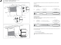
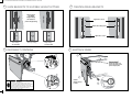
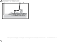
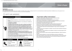
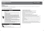
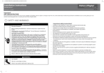
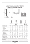
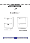
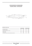
(1,1) -1- 590018A DD36SDD90S DoorPanelPrep USCANZGB.indd 22/2/10 1:49:22 PM
Front panel preparation (Integrated models only)
DishDrawer®
DD36STI, DD90S(H)TI models
US CA NZ AU GB IE
Important!
SAVE THESE INSTRUCTIONS
The models shown in this document may not be available in all markets and are subject to change at any time. For current details about model and specification availability in your country, please visit our local
website listed at the end of this document or contact your local Fisher & Paykel dealer.
1 SAFETY AND WARNINGS
WARNING!
Electrical shock hazard
WARNING – To reduce the risk of electric shock, fire, or injury to persons, the
installer must ensure that the DishDrawer® is completely enclosed at the time of
installation.
Before fitting the front panel and connecting the integrated badge, make sure
that the DishDrawer® is completely enclosed by cabinetry, and disconnected from
the power supply.
The integrated badge must be electrically connected by a suitably qualified
installer.
Failure to follow these warnings may result in electrical shock, injury or fire.
WARNING!
Cut hazard
Take care - panel edges are sharp.
Failure to use caution could result in injury or cuts.
Important safety instructions!
Read these instructions completely and carefully.
Ensure the product is not plugged in.
Installation of DishDrawer® panels requires basic mechanical and electrical skills.
Installation must comply with your local building and electricity regulations.
Failure to install the Dishdrawer® panels correctly could invalidate any warranty or liability claims.
(1,2) -1- 590018A DD36SDD90S DoorPanelPrep USCANZGB.indd 22/2/10 1:49:22 PM
2 PANEL PREPARATION
The following calculations assume the top of the panel is aligned with the top of the adjacent
cabinetry:
Installation diagrams for illustration purposes only
A
min. 1⁄8”
(2 mm)
min. 1⁄16p”
Air ga
B
mm
width of the panel
Measure A (the width between adjacent door/drawer fronts) and write it in the first box below,
then complete the equation.
min.
height of panel
)
(2.5 mm
min. 2.5
panel
width of
1⁄16”
(2 mm)
panel
eg.
min. 5⁄16”(8 mm)
Air gap
A
door clearance
35 7⁄16”
(900 mm)
1⁄8”
(2.5 mm)
-2x
A
panel width
=
door clearance
-2x
35 ¼”
(895 mm)
panel width
=
(min. 1⁄8” (2.5 mm))
(min. 33 11⁄16” (855 mm))
height of the panel
Measure B (door/drawer height (or equivalent)) and write it in the first box below,
then complete the equation.
5⁄16”
(8 mm)
Air gap
B
eg.
18 7⁄8”
(480 mm)
- 1⁄16” (2 mm) Air gap (TOP)
- 5⁄16” (8 mm) Air gap (BOTTOM)
=
- 1⁄16” (2 mm) Air gap (TOP)
- 5⁄16” (8 mm) Air gap (BOTTOM)
=
B
Installation diagrams for illustration purposes only
oor level.
er® near fl
w
ra
D
h
is
eD
stalling th
gram if in
ia
d
is
th
Use
panel height
18 ½”
(470 mm)
panel height
(min. 18 ½” (470 mm))
Note: when the top of the DishDrawer® has to be lower than the adjacent cabinetry, the panel can
be increased in height.
Front Panel material
panel
5⁄16”
(8 mm)
Air gap
5⁄16”
(8 mm)
Air gap
5⁄8”-13⁄16” (18 -20 mm) panel thickness
Adequately sealed to withstand moisture (122OF/50OC @ 80% RH)
(2,1) -1- 590018A DD36SDD90S DoorPanelPrep USCANZGB.indd 22/2/10 1:49:22 PM
3 PARTS SUPPLIED
Supplied separately
Attached to product
Panel mounting
screws (14)
Integrated rectangular badge (1)
(Satin chrome supplied)
4 ZONE REQUIRED FOR BADGE
Panel bracket (1)
Integrated door seal (1)
5 REMOVE PANEL BRACKET & DETACH BADGE
WARNING !
Electrical Shock Hazard
Before continuing, ensure that the product is
disconnected from the power supply.
3
Failure to follow this warnings may result in
electrical shock, injury or fire.
1
5” (127 mm)
10 1⁄16” (255 mm)
1 3⁄16” (30 mm)
1” (25 mm)
Badge
zo n e
2
1
18” (45
7 mm)
2 11⁄16” (6
9 mm)
4
(2,2) -1- 590018A DD36SDD90S DoorPanelPrep USCANZGB.indd 22/2/10 1:49:22 PM
6 ROUTE BADGE THROUGH PANEL
7 SECURE PANEL BRACKET TO PANEL
Important!
1
Use all 14 screws provided as shown.
2
1
5⁄8” (16 mm)
x14
2
8 RECONNECT BADGE
9 REATTACH PANEL
2
Important!
2
Ensure the rubber seal
between the drawer and
panel is kept in place.
1
1
WARNING !
Electrical Shock Hazard
Connect the integrated badge ground (earth) wire
to one of the two tabs provided on the panel bracket.
To ground (earth) the panel bracket, connect the
ground (earth) wire from the product to the other tab.
Failure to follow these warnings may result in
electrical shock, injury or fire.
Push the panel
in then up to
locate.
2
www.fisherpaykel.com www.fisherpaykel.ca www.fisherpaykel.co.nz www.fisherpaykel.com.au www.fisherpaykel.co.uk www.fisherpaykel.ie
590018A US CA NZ AU GB IE 03.10
(1,1) -2- 590018A DD36SDD90S DoorPanelPrep USCANZGB.indd 22/2/10 1:50:34 PM
Front panel adjustment (Prefinished models only)
DishDrawer®
DD36SDFTX, DD90SDFTM, DD90SDF(H)TX models
US CA NZ AU GB IE
Important!
SAVE THESE INSTRUCTIONS
The models shown in this document may not be available in all markets and are subject to change at any time. For current details about model and specification availability in your country, please visit our local
website listed at the end of this document or contact your local Fisher & Paykel dealer.
If, after installation, the front panel of your DishDrawer is not correctly aligned with the front panels of surrounding cabinetry, it can be adjusted as follows.
1 SAFETY AND WARNINGS
WARNING!
Electrical shock hazard
WARNING – To reduce the risk of electric shock, fire, or injury to persons, the
installer must ensure that the DishDrawer® is completely enclosed at the time of
installation.
Before fitting the front panel and connecting the controls, make sure that the
DishDrawer® is completely enclosed by cabinetry, and disconnected from the
power supply.
The controls must be electrically connected by a suitably qualified installer.
Failure to follow these warnings may result in electrical shock, injury or fire.
WARNING!
Cut hazard
Take care - panel edges are sharp.
Failure to use caution could result in injury or cuts.
Important safety instructions!
Read these instructions completely and carefully.
Ensure the product is not plugged in.
Installation of DishDrawer® panels requires basic mechanical and electrical skills.
Installation must comply with your local building and electricity regulations.
Failure to install the Dishdrawer® panels correctly could invalidate any warranty or liability claims.
(1,2) -2- 590018A DD36SDD90S DoorPanelPrep USCANZGB.indd 22/2/10 1:50:34 PM
2 DISCONNECT FROM POWER SUPPLY
3 REMOVE FRONT PANEL
2
WARNING !
Electrical Shock Hazard
Disconnect the DishDrawer from the power supply.
1
Failure to follow this warning may result in
electrical shock, injury or fire.
4 DETACH CONTROLS
5 LOOSEN PANEL BRACKETS
2
1
Lie the door panel flat on its front
on a protected surface.
Be careful not to damage the handle.
2
1
Loosen these screws
Remove these fixing screws
3
Loosen these screws
(2,1) -2- 590018A DD36SDD90S DoorPanelPrep USCANZGB.indd 22/2/10 1:50:34 PM
6 SLIDE BRACKETS TO SUITABLE HEIGHT SETTING
7 TIGHTEN PANEL BRACKETS
There are three
pre-drilled
height settings.
Tighten these screws
Slide brackets to
preferred height setting.
Replace these fixing screws
Tighten these screws
Low setting
- 1⁄16”(1.5 mm)
Factory setting
High setting
+ 1⁄16”(1.5 mm)
8 RECONNECT CONTROLS
9 REATTACH PANEL
2
2
Important!
Ensure the rubber seal
between the drawer and
panel is kept in place.
1
1
WARNING !
Electrical Shock Hazard
Connect the ground (earth) wire of the controls
to one of the two tabs provided on the panel bracket.
To ground (earth) the panel bracket, connect the
ground (earth) wire from the product to the other tab.
Failure to follow these warnings may result in
electrical shock, injury or fire.
Push the
panel in then up
to locate.
2
(2,2) -2- 590018A DD36SDD90S DoorPanelPrep USCANZGB.indd 22/2/10 1:50:34 PM
10 RECONNECT THE POWER SUPPLY
www.fisherpaykel.com www.fisherpaykel.ca www.fisherpaykel.co.nz www.fisherpaykel.com.au www.fisherpaykel.co.uk www.fisherpaykel.ie
590018A US CA NZ AU GB IE 03.10