1
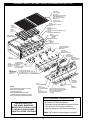
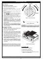
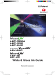
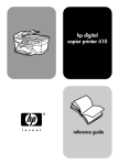
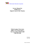
PETERSON'S SINCE 1937 REGAL II GOURMET SERIES OUTDOOR GAS BARBECUE 82,000 BTU NOTICE TO INSTALLER: These instructions must be left with the consumer NOTICE TO CONSUMER: Retain for future reference REGAL II GOURMET BRICK OR CABINET OPENING Front to Back Depth 23-3/4", Width 32-1/4" Height 12", Open Front INSTALLATION AND OPERATING INSTRUCTIONS IMPORTANT: READ THESE INSTRUCTIONS CAREFULLY BEFORE STARTING INSTALLATION FOR YOUR SAFETY IF YOU SMELL GAS: 1. 2. 3. 4. Shut off the gas to the appliance. Extinguish any open flame. Open lid if equipped with an oven. If odor continues, immediately call your gas supplier or Fire Department. FOR YOUR SAFETY 6244 012902 1. Do not store or use gasoline or other flammable vapors and liquids in the vicinity of this or any other appliance. 2. A Propane cylinder not connected for use shall not be stored in the vicinity of this or any other appliance. CODE AND SUPPLY REQUIREMENTS: This Barbecue must be installed in accordance with local codes and ordinances, or in the absence of local codes, with the latest National Fuel Gas Code, ANSI Z223.1. IN CANADA: The Barbecue must include the Canadian Certification mark and bilingual marking with bilingual instructions to comply with the Canadian Interprovincial Gas Advisory Council (IGAC) requirements. This appliance and its individual shutoff valves must be disconnected from the gas supply piping system when testing the system at pressures in excess of ½ psig. This appliance must be isolated from the gas supply piping system by closing its individual manual shutoff valves during any pressure testing of the gas supply system at pressures up to and including ½ psig. WARNING: Improper installation, adjustment, alteration, service or maintenance can cause injury or property damage. Refer to this manual. For assistance or additional information consult qualified installer, service agency or the gas supplier. CONTENTS Parts List (Exploded view) Planning for Installation Installing the Barbecue Adjusting the Barbecue Safety and Maintenance Use and Care Lighting Instructions Pg. 2 Pg. 3 Pg. 4-5 Pg. 5 Pg. 6 Pg. 6-7 Pg. 8 Robert H. Peterson Co. • 14724 East Proctor Avenue, • City of Industry, CA 91746 No. L-C2-02902 1 FIRE MAGIC REGAL II GOURMET SERIES GAS BARBECUE PARTS LIST 3520 - 22"x6" Cast Iron Grid (5) 3527 - 22"x6" Porcelainized Cast Iron Grid (5) w/Non-Stick Matte Finish 3540 - 22"x15" Porcelainized Steel Grid (2) 3544-S - 22x10 Stainless Steel Grid (3) 3000-07 Regal II Barbecue Frame liner, Porcelain 3055-S 7 Center Flavor Grid (1) 3041-25 Brass BBQ Burner (6) 3041-30 Porcelain Coated Cast Iron BBQ Burner (6) 3041-40 Stainless Steel BBQ Burner (6) 3053-S 10 Flavor Grid (2) 3000-117 Mounting Bracket (2) 3199-15 Electrode Assembly w/Wiring (1) 3990-0035 U Nut Receptacle (2) 3048-01 Air Shutter (6) 3048-03 Spring, Air Shutter (6) ** 3980-4105 & 3990-0010 1/4-20 x 5/8 Stainless Bolt & Nut (4) 3172-12-01 Mounting Plate, Manifold and Label (1) *** 3199-23-1 Spark Generator w/Lock Stem (1) 3150-12 Heatshield (3) 3172-09 ValveManifold w/Valves & Fittings (1) 3985-2105F 8-32 x 5/8 Stainless Tapping Screw (2) Regal Manifold (1) 1/2"Flare Fitting (1) BBQ Valve (3) Elbow (3) 1/8" Pipe Plug (1) 3/8" Pipe Plug (1) 3197-10 (3197-10P for L.P.) Burner Manifold Assembly for 2 Burners (3) *Orifice (#52 D.S.), Nat. (2) *Orifice (#57 D.S.), Propane (2) 3/4 Pal Nut (2) Regal Burner Manifold (1) NOTES: *Verify Proper Orifice for Natural or L.P. Gas. One set per unit as specified. **2 of same bolt & nut are used to attach Mounting Plate to frame. 3078G Drip Tray (1) 3172-04 Face, Regal Grmt. Porcelain Complete(1) or 3172-06 Face, Regal Gourmet Stainless Complete(1) 3012 3000-65 Valve Knob (3) Bezel w/ Pad (3) 3000-12 Fastener Set, Porcelain Face 3000-12-S Fastener Set, Stainless Steel 8-32 Screw Fastener Set includes 7/8" Screw, Finish Washer & "U" Nut (2) 3199-23-02 Ignitor Knob Lock-On (1) Lighting Instructions ***If the Generator is not attached to the Face, specify part # 3199-23 for Generator w/Bracket. TOOLS REQUIRED FOR INSTALLATION • #2 (medium) Phillips screwdriver • Two medium size adjustable wrenches or pliers • *3/8" wrench or 3/8" socket screwdriver • Pipe joint compound resistant to all gasses INSTRUCTIONS FOR FIRE MAGIC BARBECUE MODELS NO. 3197S thru 3198S 3190S thru 3193S PACKAGE 5390SF thru 5393SF PORTABLE *Note: 3/8" socket if orifice change is required. 2 PLANNING FOR INSTALLATION OF YOUR REGAL II GOURMET SERIES BARBECUE WHERE TO INSTALL YOUR GAS BARBECUE Fire Magic Gas Barbecues are designed for outdoor use only. WARNING: Built-in models must be installed in masonry or other type of fireproof enclosure. The unit is not insulated and therefore must be installed with 18" of side and back clearance from unprotected combustible materials such as wood, plastic or stucco with wood framing. Figure 1 - Ventilation Diagram FOLLOW ALL WARNINGS PROVIDED WITH PROPANE GAS CYLINDERS. Never locate a cylinder under or near the Barbecue unless sufficient ventilation and shielding is provided to prevent any heating of the cylinder, regulator and rubber hose. With our Insulating Liner (Part #3175-50) you can safely install your Fire Magic Barbecue in wood cabinetry or other combustible enclosure. For easy installation of your Fire Magic Barbecue a Masonry Installation Hanger (Part #3175-70 for black finish & 3175-80 for Stainless Steel) is available. It eliminates the requirement for any type of support structure under the Barbecue. This hanger can not be used in conjunction with the Insulating Liner above. Propane Cylinder Enclosures To prevent invisible combustible gas from accumulating in the cylinder enclosure, you must provide adequate ventilation. This is accomplished by EITHER one side of the gas cylinder enclosure left completely open to the outside OR by providing four (4) ventilation openings. Two openings are to be at the cylinder valve level (Approx. 16” above the floor) and at opposite walls of the enclosure. Two more openings must be at the floor level at opposite sides of the enclosure. The floor level openings must start at the floor and shall extend no higher than 5” above the floor. Each opening must have a minimum of 10 square inches (64.5 cm2) of free area. To achieve the proper ventilation, you may drill a series of holes, omit the grout from masonry joints or replace a brick with a hardware cloth screen. If the floor in the cabinet is raised and the space beneath the cabinet is open to the outside, the lower ventilation openings may be in the floor. Do not install this unit under unprotected flammable surfaces. Do not install or use this appliance inside a building, garage, or any other enclosed area including recreational vehicles or boats. This is a slide-in type unit designed to fit into open-front enclosures. The Front Panel (Face) of the unit is removable for gas hookup, servicing and Burner adjustment. The Face must therefore be removable after you install the unit. INSTALLER NOTE: This unit should be installed so that it can be removed at a later date if factory service is required. Any protrusion into the Barbecue enclosure may obstruct the frame and prevent the unit from sliding into place (see "Gas Supply Plumbing Requirements", on page 4). FOR YOUR SAFETY, you must provide these openings for drainage, replacement air and cross ventilation of any storage area exposed to possible leakage from gas connections, the Barbecue or Propane gas cylinder. INSURING PROPER COMBUSTION AIR AND COOLING AIR FLOW You must maintain proper air flow for your Fire Magic Barbecue to perform as it was designed (Figure 1). If airflow is blocked in any way, overheating and poor combustion will result. Make sure not to block the 1" front air inlet along the bottom of the Barbecue Face or the air vent openings along the outside-left and right edges of the Frame. Note: The 1" front air space also allows convenient access to the Drip Tray. IMPORTANT: Additional requirements for safe use of Propane gas and gas cylinders appears on pg. 6 of this manual. Household Propane Gas Service Consult your gas supplier for ventilation requirements when connecting to a household Propane supply. NOTE: Only Fire Magic Barbecue Models with the suffix -PA- in the model number are approved by C.S.A. for self contained Propane cylinders. Supplemental instructions are supplied with each self contained unit. VENTILATION OF ENCLOSURES When using Propane gas, take EXTREME CAUTION to ensure ample ventilation of gas vapor. Propane gas vapor is invisible and heavier than air. A DANGEROUS EXPLOSION could occur, resulting in SERIOUS INJURY OR LOSS OF LIFE, if Propane gas is allowed to accumulate and is then ignited. ELECTRICAL OUTLETS Electrical outlets in the vicinity of the Barbecue, which might be used for Rotisserie motors or other appliances, must be properly grounded. Only one Propane gas cylinder may be located in an enclosure. Extra or spare cylinders must be stored outdoors out of the reach of children and outside of any building, garage or other enclosed area. READ AND Installer and User Note: Keep electrical supply cords away from all heated surfaces. 3 Apply only joint compounds that are resistant to all gasses on all male pipe fittings. Make sure to tighten every joint securely. Do not use pipe joint compound to connect flare fittings. EXHAUST REMOVAL If installed under a patio roof, the grill area should be fully covered by a non-combustible chimney and exhaust hood. An exhaust fan with a rating of up to 1000 CFM may be necessary to efficiently remove smoke and other cooking by-products from the covered area. Installation in fully-enclosed patio areas is not recommended. The gas supply pipe should enter from the rear wall of the enclosure behind the Barbecue unit, at least 2" from either side, and between 2" and 8" above the floor as illustrated by the shaded area in Figure 2. If it is not possible to stub the gas line in from the back of the enclosure, the connection may be made through the floor at the rear of the enclosure. Install the gas line stub at least 2" away from the side and back walls, but within 6" of the back wall as illustrated by the shaded area in Figure 2. GAS SUPPLY PLUMBING REQUIREMENTS Rigid 1/2" or 3/4" black steel pipe, or local code approved pipe for temperatures up to 800°F (427°C), is required to conduct the gas supply into the enclosure opening for connection to the unit. SAFETY NOTE: An external valve (with a removable key) in the gas line is necessary for safety when your Barbecue is not in use. It also provides for convenient maintenance and repair. 23 3/4" 28 1/4" 6" GAS SUPPLY AND MANIFOLD PRESSURES: 12" 4" For Natural Gas - Normal 7" Water Column, Minimum 3 1/2", Maximum 10-1/2". For Propane gas - Normal 11" Water Column, Minimum 8", Maximum 13". 2" 2" 32 1/4" Figure 2 - Gas Stub Diagram INSTALLING YOUR FIRE MAGIC REGAL II GOURMET SERIES BARBECUE c. Lift off and remove one of the three galvanized steel Heatshields which are resting over the necks of each pair of Burners. Perform the following checks before installing your Barbecue: 1. CHECK FUEL ORIFICES FOR PROPER SIZE d. Check the orifice size by lifting a Burner up off of the stainless steel screw, or peg, at the back side of the unit and pulling it away from the orifice. The drill size is stamped on the face of each orifice. Be sure not to lose the Air Shutter or Air Shutter Spring which may become detached when the Burner is removed. Your Regal II Barbecue is equipped with fuel orifices for Natural gas, unless otherwise indicated. To use with Propane gas, you must install smaller orifices to avoid hazardous overheating. The proper orifice size for Natural Gas is #52 (drill size). The proper orifice size for Propane gas is #57 (drill size). e. Change all six orifices if necessary, following instructions provided with your replacement orifices (furnished with all Fire Magic Gas Barbecues). 2. IF YOU ARE NOT SURE YOU HAVE THE CORRECT BARBECUE BURNER ORIFICE SIZE: a. Remove the Cooking Grids and Flavor Grids from your Barbecue. f. After checking orifice drill size, install the Air Shutter Spring and the Air Shutter over the orifice holder fitting, between the Burner and the Pipe Manifold, in the order and position shown in Figure 3. b. If the gas supply has been connected, make sure the Burner Valves are in the “Off” position. Then pull the Valve knobs from their stems. Use a Phillips screwdriver to turn the Face Fastener Screws counter clockwise to release the Face and remove it from the Barbecue. Make sure to retain the screws and finish washers until you are ready to reattach the Face. g. Carefully place the Burners back on the screws or pegs so that the brass orifice and orifice holder fittings project deeply into the Burners. h. Replace the galvanized Heatshields. NOTE: Carefully lift the face away from the frame. The Spark Generator for the ignition system is attached to the inside of the face panel. The Ignitor Knob need not be detached, but the wires must be unplugged from the generator before the face is removed. ORIFICE HOLDER/BURNER MANIFOLD BURNER BURNER NECK SPRING Figure 3 - Burner Orifice Diagram AIR SHUTTER 4 ORIFICE NOTCH 3. CONNECT THE GAS SUPPLY TO BARBECUE a. You will need an CSA approved stainless steel flex connector to bring the gas supply from the gas line stub to the Valve Manifold. A 1/2" x 36" or 48" flex connector with 1/2" flare to 1/2" pipe adapter on one end, and a 1/2" flare female fitting on the other end is suitable for most installations. CAUTION: Use only stainless steel flex connectors that are C.S.A. listed. FLAVOR GRID BURNER CAPS BURNER WARNING: A rubber or plastic connector will rupture or leak, resulting in an explosion or serious injury if used inside the Barbecue enclosure. Figure 4 - Flavor Grid Diagram f. Make sure the Barbecue Burner valves are in the "OFF" position. Turn the gas supply on. Then carefully check all gas connections for leaks with a brush and soapy water before lighting. NEVER USE A MATCH OR OPEN FLAME TO TEST FOR LEAKS. b. Make sure that your gas supply is turned off! Then connect the 1/2" pipe adapter fitting supplied with the stainless steel flex connector to the gas supply stub. Use pipe joint compound that is resistant to all gasses on the male pipe fitting and tighten securely. Do not use pipe joint compound to connect the Flare Fittings. g. Refer to the "Air Shutter Adjustment" Instructions below before replacing Barbecue face and knobs. c. Slide your Barbecue into place, making sure not to pinch or kink the gas connector. 4. INSTALL THE FLAVOR GRIDS a. Place the Flavor Grid Burner caps directly on the Burners. Make sure the notched end of the Burner Cap rests over the Ignitor Box (Figure 4). Center the Grids over the Burners with the open side up. This allows heat from the Burners to be evenly distributed throughout the cooking area. Flavor Grids heat and cool quickly, making your Fire Magic Barbecue very responsive to the changes you specify in grill temperature. d. Bring the flex connector around the left-hand side of the Barbecue. Use the Locator Angle Brackets on the left lower-frame to position the flex connector. Continue the flex connector along the left side to the front of the unit and the Valve Manifold Inlet. Be careful not to block the 1" Front Vent opening as this will obstruct Drip Tray removal. e. Connect the flex connector to the Flare Fitting on the Manifold Inlet. Support the Manifold Inlet Fitting with a wrench to avoid applying excessive torque to the Manifold Assembly while tightening this connection securely. Do not use pipe compound on Flare Fittings. The Flavor Grids are made of stainless steel. They are rust resistant and may be cleaned with standard oven cleaners. ADJUSTING YOUR BARBECUE IMPORTANT: This appliance will not light and will not heat evenly or cook properly unless the Air Shutters are adjusted following installation (Reference "Air Shutter Adjustment", below). PARTIALLY OPEN FIGURE 5A TAB DIMPLE NOTCH Burner Air Shutters are easily accessed by removing the Front Panel (Face). The Air Shutters are located at the front of the Burners behind the Face (see Parts List). The Air Shutter has a small dimple (see Figure 5A), which allows it to lock into notches in the burner face. This prevents the air shutter from moving. Close the air shutters by turning the tabs to a vertical position. (Figure 5B). Light your Barbecue in accordance with lighting instructions (Page 8) and burn for 2 minutes with the valves on high and the oven open. CLOSED FIGURE 5B FLAME OFF PORTS (TURN TABS) FLAME ON PORTS Figure 5A & 5B - Air Shutter Adjustment Diagram AIR SHUTTER ADJUSTMENT ADJUSTING THE FLAME HEIGHT After burning for 2 minutes, open the Air Shutters until the flames lift off, or appear not to be touching the Burners. Then begin closing the Air Shutters until the flames appear to burn while touching the Burner Ports (Figure 5B). You may then see short yellow tips on the flames. If flames are a lazy yellow, open the Air Shutters until the flame is blue with yellow tipping. The large knobs on the Face of the Barbecue control the Valves and adjust flame height. The first position is “High,” the second “Medium” and the final “Low.” Flame height can also be set anywhere between the High, Medium, and Low settings for all cooking requirements and tastes. Height of the flame with the valve in low position may be regulated by means of a small adjusting screw in the center of the valve stem. This screw is accessible by removing the plastic valve knob which pulls straight off the end of the valve stem. NOTE: Barbecues in some installations achieve a better air/gas mixture and will ignite more quickly if the valve is first turned beyond High to Medium or Low for lighting. 5 BARBECUE SAFETY AND MAINTENANCE SAFETY INFORMATION Every time you use your Barbecue, make sure that: DRIP COLLECTION SYSTEM 1. The area around the Barbecue is clear of flammable substances such as gasoline, yard debris, wood, etc. The Drip Collector in this Fire Magic Barbecue is part of the unit’s main frame, and is located below the Burners. The Drip Collector has three holes which allow excess drippings to fall through during cooking while separating the firebox from the drip tray. 2. There is no blockage of the air flow through the vent space located below the Face of the unit. 3. The Drip Collector allows you to brush or scrape residue from the Barbecue inner liner into the Drip Tray. Regular cleaning of your Barbecue interior with oven cleaner or Fire Magic Foaming Barbecue and Grill Cleaner, will prevent grease fires. When using Propane gas: a. The special ventilation openings in the enclosure are kept free and clear of debris. b. If connected to a Propane cylinder, the rubber hose attached to the Regulator is carefully inspected before each use. PREPARING THE BARBECUE FOR COOKING To extend the life of your Fire Magic Barbecue, follow these steps prior to cooking: c. The Propane cylinder, Regulator and rubber hose are installed in a location not subject to heating above 125° F (51° C). 1. Begin by heating the unit at a normal cooking temperature for several minutes. 4. The Burner flames burn evenly along both sides of each Burner with a steady flame (mostly blue with yellow tipping). See Air Shutter Adjustment. If Burner flames are not normal, check the orifice and Burner for insects or insect nests (see pg. 4Checking Fuel Orifices). 2. Then open the Control Valves to the “High” setting to burn off residue remaining from prior use. 3. When the Barbecue has heated sufficiently, set heat to the desired cooking level. 4. When using a smoke oven, closing the cover during the preheat period will accelerate the preparation process. Do not operate unattended at High Flame as cooking temperatures will quickly be exceeded. 5. The Drip Collector holes are clear and unobstructed. Excessive grease deposits can result in a grease fire. 6. The in-line gas valve or gas cylinder valve is always shut off when the Barbecue is not in use. WARNING: Never cover the entire cooking or grill surface with griddles or pans. Overheating will occur and Burners will not perform properly when combustion heat is trapped below the cooking surface. CAUTION: Never spray water on a hot Barbecue as this may damage the unit. USE AND CARE OF YOUR BARBECUE FLAVOR FROM WOOD CHIPS OR CHARCOAL CARE OF STAINLESS STEEL COMPONENTS Convenient Fire Magic Gourmet Grilling Chips are sold in several different popular wood types. These chips are pre-moistened and sealed in cans which can be opened, by lifting the tabbed lid, before placing the entire can on the Flavor Grid to add natural wood smoke flavor to the food you grill. There is no mess to clean up. Just discard the can of ashes after there is no longer any wood smoke aroma. If your Barbecue has a stainless steel oven and front panel, the following care instructions will keep your unit looking and working like new. Stainless steel components are constructed of the finest prime grade type 304 stainless steel. Meticulous attention has been given to maintain the attractive finish throughout the manufacturing process. Like the stainless steel used in commercial kitchens, your Barbecue requires regular cleaning and occasional buffing to maintain its bright, clean appearance. You may also add wood chips, wood chunks or the natural wood charcoal of your choice to the Flavor Grid. We recommend placing wood outside the direct cooking zone or wrapping it in perforated aluminum foil. Soaking wood before use will slow burning and increase smoke flavor. Wood and charcoal ash will remain in the Flavor Grid after use. The Grid can be easily removed and cleaned when the unit has fully cooled. Deposits of dirt and grease can be removed easily with Fire Magic Foaming Barbecue and Grill Cleaner. Deposits should be removed before they are allowed to bake onto the finish. To remove more stubborn deposits, use a scouring pad recommended for stainless steel. Be sure to always rub in the direction of the polishing lines (Figure 6). Oven cleaner may be used, according to manufacture's instructions, to remove 6 USE AND CARE OF YOUR BARBECUE cont. with strong cleaning solutions, including oven cleansers. We do not recommend ordinary steel or wire brushes, which may leave tiny metal particles on the grids which cause discoloration, but not permanent damage. WIPE WITH GRAIN PORCELAIN COATED CAST IRON GRIDS PETERSON'S Fire Magic porcelain-finished cast-iron grids are coated with a special high-temperature porcelain in a matte (satin) finish. This special matte-finish porcelain coating provides a stick resistant cooking surface that makes outdoor barbecuing easy and enjoyable. And, because it resists corrosion, the finish also increases cooking grid durability to provide years of cooking enjoyment. For best cooking performance, the wide side of the grid bars should face up. SINCE 1937 BARBECUE AND GRILL CLEANER CARE AND MAINTENANCE (Porcelain Coated) Figure 6 - Always rub with the grain A spray coat of vegetable oil and light brushing with a brass grid brush before and after use is all it takes to maintain cooking readiness and ensure long life. cooked-on food deposits. Special cleaning agents and polishing pads recommended for stainless steel are available at your local Barbecue dealer, hardware store or supermarket. PROTECTING PARTS AND FINISH Barbecue covers will protect the finish and extend the life and appearance of Fire Magic Barbecues equipped with smoke ovens. The covers are designed to protect the finish against scratches, corrosion and oxidation. Each cover has been cut and sewn by hand to fit a particular smoke oven model. Flaps extend from the sides and back. In windy areas, place weights on the flaps or inside the sleeve on the flaps to keep the cover from blowing off. CAUTION: Never use ordinary steel wool or steel brushes on stainless steel. Tiny particles left behind may rust and stain the finish. Abrasive pads recommended for restoring the grain in stainless steel will, over a period of time, scratch or dull the surface of glass or porcelain-coated products. BURNER MAINTENANCE Fire Magic Burners are constructed of heavy-duty Cast Stainless Steel (Cast Brass and Porcelainized Cast Iron Burners are also available) and will withstand many years of outdoor use, if ordinary precautions are taken. Once or twice a year inspect the Burners and determine if dirt or debris is building up excessively. Burners can be removed and scraped to remove debris from ports. Replace Burners immediately if they show any signs of weak or thin walls. Refer to the bottom of page 4, figure 3 for installing Burners. PETERS ON'S SINCE STAINLESS STEEL COOKING GRIDS Fire Magic stainless steel cooking grids are finished with a special matte (satin) finish. This special mattefinish provides a more stick-resistant cooking surface that makes outdoor barbecuing easy and enjoyable. And, because it is made of type 304 stainless steel, you'll enjoy a lifetime of outdoor cooking. For best cooking performance, follow the simple steps of Care and Maintenance after every use. Fire Magic Stainless Steel Cooking Grids are warranted for as long as you own them. CARE AND MAINTENANCE (Stainless Steel Grids) To maintain your Stainless Steel Cooking grids we recommend lightly brushing the grids after use with a brass or stainless steel wire brush. Before use, brush again if necessary and spray a light coat of vegetable oil over the cooking surface. Discoloration or stubborn food particles can be removed with a heavy-duty abrasive or stainless steel scouring pad. Grills can also be washed in an automatic dishwasher or cleaned 7 1937 LIGHTING INSTRUCTIONS Follow these instructions each time you light your Fire Magic Barbecue. OFF MARKER 1. Read these instructions before lighting. TO 2. Open the lid of the Smoke Oven. OFF 3. Turn all three Barbecue gas valves to the “OFF” position. PU TUSH RN TO HI LIGHT 4. Turn on the gas at the source outside of the Barbecue enclosure. FF O TU RN RN TU O N TO FOR AUTOMATIC LIGHTING: HIGH TO LIGHT NOTE: DO NOT turn on more than one valve at a time for either automatic or manual lighting. Adjacent Barbecue Burners will cross-ignite. ME D 5. Push the center gas valve and turn to “HIGH” then immediately turn the ignitor knob several times in the direction of the arrows. Figure 7 - Valve Control Knob CAUTION: If the Burners do not light, IMMEDIATELY turn the valve to “OFF” and WAIT 5 MINUTES before repeating step 5. If the Burners still do not light, refer to the instructions below for manual lighting. NOTE: Barbecues in some installations achieve a better air/gas mixture and will ignite more quickly if the valve is first turned beyond High to Medium or Low for lighting. Figure 8 - Match Holder REMEMBER: FOR SAFE MANUAL LIGHTING, PLACE A BURNING MATCH OR BUTANE LIGHTER BESIDE THE BURNER - THEN TURN ON THE GAS (Figure 9). FOR MANUAL LIGHTING: CAUTION: Always wait 5 minutes for gas to clear after any unsuccessful lighting attempt. 1. Follow steps 1 through 4 above. 2. Insert either a burning long-barrel butane lighter, a burning long-stem match or a burning match held by a wire extension holder through the Cooking Grid to the Burners below the Flavor Grid. 3. While holding the match or lighter flame next to the Burner, depress the appropriate Valve knob and turn it counterclockwise to the “HIGH” position. Adjacent Burners will cross-ignite. 4. If the Burner does not light, IMMEDIATELY turn the valve to “OFF” and WAIT 5 MINUTES before repeating steps 2 through 4 of the Manual lighting instructions. Replacement parts may be obtained from your nearest Fire Magic Dealer. For assistance in locating a dealer, please contact our factory at the address listed below. Figure 9 - Manual Lighting IF YOU SMELL GAS 1. Shut off gas to the appliance. 2. Extinguish any open flame. 3. Open lid if equipped with oven. 4. If the odor continues, immediately call your gas supplier or fire department. Robert H. Peterson Co. • 14724 East Proctor Avenue, • City of Industry, CA 91746 8