1
Installation, Operation and
Maintenance Manual
Oil Fired Warm Air Furnaces
WML-C AND MPL-B
(Down-Flow or Horizontal Model)
ALL INSTALLATIONS MUST MEET ALL
LOCAL, PROVINCIAL/STATE, AND
FEDERAL CODES WHICH MAY
DIFFER FROM THIS MANUAL
ECR International Limited
OLSEN Division
Read this complete manual before
beginning installation. These
instructions must be kept with the
furnace for future reference.
TABLE OF CONTENTS
INTRODUCTION..........................................................................................................................................................................3
HEAT LOSS.................................................................................................................................................................................3
LOCATION OF UNIT ...................................................................................................................................................................3
AIR CONDITIONING....................................................................................................................................................................4
COMBUSTION AIR......................................................................................................................................................................5
CHIMNEY VENTING....................................................................................................................................................................5
DRAFT REGULATOR CONTROL...............................................................................................................................................5
OPTIONAL SIDE WALL VENTING .............................................................................................................................................7
OIL TANK ....................................................................................................................................................................................7
PIPING INSTALLATION..............................................................................................................................................................7
ELECTRICAL CONNECTIONS ...................................................................................................................................................7
FAN TIMER BOARD AND LIMIT CONTROL..............................................................................................................................8
CIRCULATING AIR BLOWER ....................................................................................................................................................8
HUMIDIFIER ................................................................................................................................................................................9
OIL BURNER...............................................................................................................................................................................9
FURNACE INSTALLATION SET-UP ........................................................................................................................................10
MAINTENANCE AND SERVICE ...............................................................................................................................................11
OPERATING INSTRUCTIONS ..................................................................................................................................................12
APPENDIX A- WML-C AND MPL-B BURNER SET UP............................................................................................................13
A.1 OIL BURNER AIR ADJUSTMENT......................................................................................................................................14
A.2 BURNER ELECTRODES....................................................................................................................................................14
A.3 START UP...........................................................................................................................................................................14
A.4 SPECIAL INSTRUCTIONS FOR UNITS EQUIPPED WITH RIELLO BURNERS...............................................................14
TABLE A-6 DIRECT DRIVE BLOWER SET-UP .......................................................................................................................15
TABLE A-8 DIRECT DRIVE BLOWER CHARACTERISTICS ..................................................................................................15
TABLE A-9 GENERAL DIMENSIONS (INCHES) .....................................................................................................................16
APPENDIX B: WIRING DIAGRAMS .........................................................................................................................................17
OPERATION OF OIL BURNER.................................................................................................................................................21
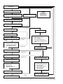
APPENDIX C-R7184 TROUBLESHOOTING ............................................................................................................................22
R7184 DETAILED SEQUENCE OF OPERATION (FIGURE 7).................................................................................................22
TABLE C-1: ELECTRONIC FAN TIMER BOARD (EFT) DETAILED SEQUENCE OF OPERATION ......................................25
R7184 LED DIAGNOSTIC LIGHT .............................................................................................................................................26
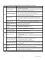
TABLE C-3: R7184 TROUBLESHOOTING ..............................................................................................................................27
TABLE C4: SYSTEM AND GENERAL TROUBLESHOOTING ................................................................................................29
FINAL CHECK OUT ..................................................................................................................................................................31
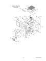
PARTS LISTING: COUNTERFLOW HORIZONTAL MODEL: WML C .....................................................................................32
HOMEOWNER’S REFERENCE TABLE ...................................................................................................................................38
NOTES:......................................................................................................................................................................................39
2
30318 R4 9/9/2005
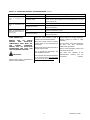
IMPROPER
INSTALLATION
MAY
CREATE A CONDITION WHERE THE
OPERATION OF THE PRODUCT
COULD CAUSE PERSONAL INJURY
OR PROPERTY DAMAGE.
IMPROPER
INSTALLATION,
ADJUSTMENT,
ALTERATION,
SERVICE OR MAINTENANCE CAN
CAUSE INJURY OR PROPERTY
DAMAGE. REFER TO THIS MANUAL
FOR ASSISTANCE OR ADDITIONAL
INFORMATION,
CONSULT
A
QUALIFIED INSTALLER, SERVICE
AGENCY OR THE FUEL SUPPLIER.
THIS PRODUCT MUST BE INSTALLED
IN STRICT COMPLIANCE WITH THESE
INSTALLATION INSTRUCTIONS AND
ANY APPLICABLE LOCAL, STATE,
AND NATIONAL CODES INCLUDING
BUT NOT LIMITED TO: BUILDING,
ELECTRICAL
AND
MECHANICAL
CODES.
The furnace area must not be used as a
broom closet or for any other storage
purposes, as a fire hazard may be
created. Never store items such as the
following on, near or in contact with the
furnace:
1.
Spray or aerosol cans, rags,
brooms,
dust
mops,
vacuum
cleaners or other cleaning tools.
2.
Soap powders, bleaches, waxes or
other cleaning compounds; plastic
items or containers, gasoline,
kerosene, cigarette lighter fluid, dry
cleaning fluids, or other volatile
fluids.
3.
Paint thinners or other painting
materials and compounds.
4.
Paper bags, boxes, or other paper
or cardboard products.
Never operate the furnace with the
blower door removed. To do so could
result in serious personal injury and/or
equipment damage.
DO
NOT
USE
GASOLINE,
CRANKCASE OIL, OR ANY OTHER
OIL CONTAINING GASOLINE AS A
FUEL FOR THIS FURNACE.
INTRODUCTION
Please
read
these
instructions
completely and carefully before installing
and operating the furnace.
The furnace must be installed and set up
by a qualified contractor.
Model WML-C is an oil fired forced air
multi-positional furnace, with an output
capacity range of 58,000 BTU/Hr. to
85,600 BTU/Hr. The MPL-B is also an oil
fired forced air multi-positional furnace
with an output capacity range of 85,500
BTU/Hr. to 123,000 BTU/Hr. The WMLC AND MPL-B furnace may be installed
in the down-flow position, as well as both
left and right horizontal positions.
All models are listed with the Canadian
Standards Association, (CSA), and
comply with the standards of both the
United States and Canada for use with
No. 1 (Stove) and No. 2 (Furnace) Oil.
In the United States, the installation of
the furnace and related equipment shall
be installed in accordance with the
regulations of NFPA No. 31, Installation
of Oil Burning Equipment, as well as in
accordance with local codes.
In Canada, the installation of the furnace
and related equipment shall be installed
in accordance with the regulations of
CAN/CSA - B139, Installation Code For
Oil Burning Equipment, as well as in
accordance with local codes.
When
installation
or
application
questions arise, regulations prescribed in
the
National
Codes
and
Local
Regulations take precedence over the
general instructions provided with this
installation manual. When in doubt,
please consult your local authorities.
All models are shipped assembled and
pre-wired. The furnace should be
carefully inspected for damage when
being unpacked.
enable proper sizing of the trunk and
branch ductwork. In retrofit applications,
a building shell (overall) heat loss
calculation may be used.
In the United States, Manual J. titled,
"Load Calculation" published by the Air
Conditioning Contractors of America,
(ACCA), describes a suitable procedure
for calculating the maximum hourly heat
loss.
In Canada, the maximum hourly heat
loss may be calculated in accordance
with the procedures described in the
manuals of the Heating, Refrigeration
and Air Conditioning Institute (HRAI), or
by other method prescribed by
authorities having jurisdiction that are
suitable for local conditions.
LOCATION OF UNIT
The furnace should be located such that
the flue connection to the chimney is
short, direct and consists of as few
elbows as possible. When possible, the
unit should be centralized with respect to
the supply and return air ductwork. A
central location minimizes the trunk duct
sizing. All models may be installed on
combustible floors. Do not install the
furnace on carpet or tiled floors.
Minimum installation
listed in Table 1.
clearances
NOTE: The recommended installation
clearances do not necessarily take into
consideration the clearances necessary
to replace the air filter or perform other
routine maintenance.
DOWN-FLOW INSTALLATION
All WML-C AND MPL-B furnace models
have been assembled for installation in
the down-flow position. Maintain all
clearances to combustibles as outlined in
Table 1. Suggestion; as a measure to
prevent fuel oil from accumulating in
locations other than the fire pot, as could
be the case in the event of nozzle drip,
install the furnace with an approximate 2
degree slope from the oil burner casing
towards the fire pot. Use shims made of
noncombustible material.
HEAT LOSS
To determine the correct furnace and
firing rate for an application, it is
necessary to calculate the maximum
hourly heat loss of the building based on
local design conditions. In new
construction, the heat loss should be
calculated on a room-by-room basis to
3
are
30318 R4 9/9/2005
HORIZONTAL INSTALLATION
WML-C AND MPL-B furnaces models
are assembled and shipped ready for
installation in the down-flow position. The
furnace may be installed in either of the
horizontal
positions;
warm
air
discharging left or warm air-discharging
right by following these steps:
1.
Rotate the furnace 90° to the
desired position.
2.
Remove the three nut and washer
sets fastening the oil burner
assembly to the furnace. Rotate the
oil burner assembly to be in the
normal upright position.
3.
Re-align the oil burner assembly to
the combustion chamber (fire-pot),
and then secure into place with the
three nut and washer sets.
NON-SUSPENDED INSTALLATION
Maintain clearances to combustibles as
outlined in Table 1. Installation on a
combustible floor requires a clearance of
1 inch. This can be done by using a
noncombustible material such as oneinch thick channel iron or similar
material. The furnace must be supported
in such a way as to not allow twisting or
sagging of the cabinet. Suggestion; as a
measure to prevent fuel oil from
accumulating in locations other than the
fire pot, as could be the case in the event
of nozzle drip, install the furnace with an
approximate 2-degree slope from the oil
burner casing towards the fire pot. Use
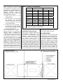
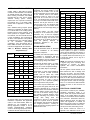
Table 1: Clearance to Combustibles
WML-C
Furnace
Location
MPL-B
Down flow
Horizontal
Down flow
Horizontal
Top
0 in.
3 in.
0 in.
3 in.
Bottom
1 in.
1 in.
1 in.
1 in.
S/A Plenum
1 in.
1 in.
1 in.
1 in.
Rear
1 in.
1 in.
1 in.
1 in.
Sides
1 in.
1 in.
1 in.
1 in.
Front
10 in.
1
10 in.
1
10 in.
1
10 in.1
Flue Pipe
9 in. 2
9 in. 2
9 in. 2
9 in. 2
Enclosure
Closet
Closet
Closet
Closet
1
2
24 inches is required for servicing.
18 inches required in the United States.
shims made of noncombustible material.
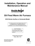
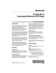
SUSPENDED INSTALLATION
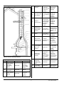
Refer to Figure 1. Maintain clearances to
combustibles as outlined in Table 1. The
furnace may be suspended by field
fabricating a cradle of angle iron and
threaded rod. Secure the furnace with 2
inch
minimum
slotted
angle
or
equivalent, as shown in Figure 1. The
furnace must be supported in such a way
as to not allow twisting or sagging of the
cabinet. Position the supports so as to
not interfere with accessing the burner
and blower compartments. Suggestion;
as a measure to prevent fuel oil from
accumulating in locations other than the
fire pot, as could be the case in the event
of nozzle drip, install the furnace with an
approximate 2 degree slope from the oil
burner casing towards the fire pot.
AIR CONDITIONING
If the furnace is used in conjunction with
air conditioning, the furnace shall be
installed in parallel with or upstream from
the evaporator coil to avoid condensation
in the heat exchanger. In a parallel
installation, the dampers or air controlling
means must prevent chilled air from
entering the furnace. If the dampers are
manually operated, there must be a
means of control to prevent the operation
of either system unless the dampers are
in the full heat or full cool position. The
air heated by the furnace shall not pass
Fig 1 Suspended Installation
4
30318 R4 9/9/2005
through a refrigeration unit unless the
unit is specifically approved for such
service.
Generally, a six-inch clearance between
the air conditioning evaporator coil and
the heat exchanger will provide adequate
airflow through the evaporator coil.
The blower speed must be checked and
adjusted to compensate for the pressure
drop caused by the evaporator coil.
Refer to Appendix B for recommended
wiring and electrical connections of the
air conditioning controls.
COMBUSTION AIR
When a furnace is installed in the full
basement of a typical frame or brick
house, infiltration is normally adequate to
provide air for combustion and draft
operation. If the furnace is installed in a
closet or utility room, two (2) ventilation
openings must be provided connecting to
a well ventilated space (full basement,
living room or other room opening
thereto, but not a bedroom or bathroom).
One opening shall be located 6" from the
top and bottom of the enclosure at the
front of the furnace. For furnaces located
in
buildings
of
unusually
tight
construction, such as those with high
quality weather stripping, caulking,
windows and doors, or storm sashed
windows, or where basement windows
are well sealed, a permanent opening
communicating with a well ventilated
attic or with the outdoors shall be
provided, using a duct if necessary. Size
all of the openings and associated
ductwork by the standards provided in
the latest Oil Installation Code editions;
NFPA 31 in the United States, CAN/CSA
B139 in Canada. Take all fuel burning
appliances in the area into consideration
when calculating combustion and
ventilation air requirements.
The Model CAS-2B-90E Furnace Boot
manufactured by Field Controls, Inc. may
be used with the furnace to obtain
combustion air from outdoors. Use of this
device does not alter the need for
ventilation air; however, it does provide a
good source of combustion air and is
connected to the oil burner.
CHIMNEY VENTING
The chimney must be sized correctly and
be in good repair. If the chimney is
oversized, there is a high risk of the flue
gases condensing resulting in damage to
the chimney and other venting parts.
This problem may be corrected by the
use of an appropriately sized chimney
liner.
If the chimney serves the WML-C
furnace only, the vent should be sized at
5-inch minimum. The MPL-B should be
6-inch minimum. The data provided in
Table 3 is based on dedicated venting. If
the furnace is to be co-vented with other
appliances, refer to NFPA 211, Standard
for Chimneys, Fireplaces, Vents, and
Solid Fuel-Burning Appliances, NFPA
31, Standard for the Installation of Oil
Burning Equipment or CAN/CSA B139,
Installation Code For Oil Burning
Equipment for correct sizing information.
NOTE: This furnace is approved for
use with L-Vent.
NOTE: Maximum temperature for LVent is 575°F (300°C).
IMPORTANT: The chimney must be
capable of providing sufficient draft at all
times for the safe removal of the
products of combustion.
The chimney should be tested under
“winter” conditions; doors and windows
closed, all other fossil fuel burning
appliances on, clothes dryer on,
bathroom fans on, etc. If the chimney
cannot overcome the competition for air,
it will be necessary to access the reason
for it, and take corrective action. If the
chimney is found to be sized correctly
and in good repair, it will probably be
necessary to re-evaluate the availability
of combustion and ventilation air, and
take corrective action.
The flue pipe should be as short as
possible with horizontal pipes sloping
upward toward the chimney at a rate of
one-quarter inch to the foot. The flue
pipe should not be smaller in cross
sectional area than the flue collar on the
furnace. The flue pipe should connect to
the chimney such that the flue pipe
extends into, and terminates flush with
the inside surface of the chimney liner.
Seal the joint between the pipe and the
lining. The chimney outlet should be at
least two feet above the highest point of
a peaked roof. All unused chimney
openings should be closed. Chimneys
must conform to local, provincial or state
codes, or in the absence of local
regulations, to the requirements of the
National Building Code.
THE
FURNACE
MUST
BE
CONNECTED TO A FLUE HAVING
SUFFICIENT DRAFT AT ALL TIMES TO
ENSURE
SAFE
AND
PROPER
OPERATION OF THE APPLIANCE.
The flue pipe must not be routed through
concealed space, because it must be
visually
checked
for
signs
of
deterioration
during
the
annual
inspection and servicing. The flue pipe
must not pass through any floor or
ceiling, but may pass through a wall
where suitable fire protection provisions
have been installed. In the United States,
refer to the latest edition of NFPA 31 for
regulations governing the installation of
oil burning equipment. In Canada, refer
to the latest edition of CAN/CSA B139
for rules governing the installation of oil
burning equipment.
NOTE: THE RECOMMENDED FLUE
DRAFT PRESSURE IS -0.02 IN. W.C.
(AS MEASURED UPSTREAM OF THE
BAROMETRIC DRAFT REGULATOR).
SHOWN IN FIGURE 1.
DRAFT REGULATOR CONTROL
This device is used in conjunction with
conventional chimney venting. This
control (or draft regulator) automatically
maintains a constant negative pressure
in the furnace to obtain maximum
efficiency. It ensures that proper
pressures are not exceeded. If the
chimney does not develop sufficient
draft, the draft control cannot function
properly. The draft regulator, must be
installed within the same room or
enclosure as the furnace, and should not
interfere with the combustion air supplied
to the burner. The control should be
located a minimum of 3 flue pipe
diameters from the furnace breeching
and installed in accordance to the
instructions supplied with the regulator.
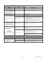
See Figure 2 and Table 2 for common
chimney problems and their remedies.
5
30318 R4 9/9/2005
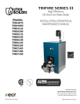
Fig. 2: Common Chimney Problems
Can be found
by light and
mirror reflecting
conditions in
chimney.
Use weight to
break and
dislodge.
Joist protruding
into chimney.
Lowering a light
on an extension
cord.
Must be
handled by
competent
masonry
contractor.
F
Break in
chimney lining.
Smoke test build smudge
fire blocking off
other opening,
watching for
smoke to
escape.
Must be
handled by
competent
masonry
contractor.
G
Collection of
soot at narrow
space in flue
opening.
Lower light on
extension cord.
Clean out with
weighted brush
or bag of loose
gravel on end
of line.
H
Offset
Lower light on
extension cord.
Change to
straight or to
long offset.
Found by
inspection from
basement.
The least
important
opening must
be closed,
using some
other chimney
flue.
D
E
Obstruction in
chimney
I
Two or more
openings to the
same chimney.
J
Loose-seated
pipe in flue
opening.
Smoke test.
Leaks should
be eliminated
by cementing
all pipe
openings.
K
Smoke pipe
extends into
chimney.
Measurement
of pipe from
within or
observation of
pipe by means
of a lowered
light.
Length of pipe
must be
reduced to
allow end of
pipe to be flush
with inside of
tile.
L
Failure to
extend the
length of flue
partition to the
floor.
By inspection or
smoke test.
Extend partition
to floor level.
M
Loose-fitted
clean-out door.
Smoke test.
Close all leaks
with cement.
Table 2: Common Chimney Problems
Refer to Figure 2
Key
Trouble
Diagnostic
Remedy
A
Top of chimney
lower than
surrounding
objects
Observation
Extend chimney
above all
surrounding
objects within
30 feet.
B
Chimney Cap
or ventilator.
Observation
Remove
C
Coping restricts
opening.
Observation
Make opening
as large as
inside of
chimney.
6
30318 R4 9/9/2005
OPTIONAL SIDE WALL VENTING
Certain WML-C AND MPL-B furnace
models are manufactured to be installed
as sidewall vented units. Please refer to
Direct Venting Instructions, P/N 28888
included with the Vent Kit for details.
Sidewall
Venting
(Direct
Venting)
requires the use of specific oil burners;
the Beckett AFII, or the Riello 40BF.
Please refer to Appendix A, Tables A2,
and A4.
Note: Sidewall venting requires special
attention to combustion air supply. There
is no natural draft in the venting system
between furnace cycles; therefore, if the
indoor pressure is negative relative to
the outdoors, the vent terminal becomes
a point of infiltration. This could lead to
oil odour control problems. This problem
is rectified by the use of ducted outdoor
air
for
combustion
(semi-sealed
combustion), using the Beckett AFII or
Riello 40BF oil burner. See Direct Vent
Instructions supplied with the Vent Kits.
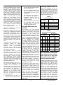
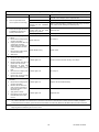
Table 3: Minimum Chimney Base
Temperatures (°F)
Nozzle
Chimney Height (ft.)
11
20
28
36
Chimney Thermal Resistance < R6
In general, the oil tank must be properly
supported and remain stable in both
empty and full condition. The oil tank
must be fitted with vent and supply pipes
to the outdoors. Refer to the abovementioned codes for sizing. The vent
pipe must be no less than 1¼ inches
I.P.S., and terminate with an appropriate
vent cap in a location where it will not be
blocked. The fill pipe must be no less
than 2 inches I.P.S., and terminate with
an appropriate cap in a location where
debris will not enter the fill pipe during oil
delivery.
If located indoors, the tank should
normally be in the lowest level, (cellar,
basement, etc.). It must be equipped
with a shut-off valve at the tank outlet
used for the oil supply. The oil tank must
be located as to not block the furnace /
room exit pathway. Observe all
clearances specified in the abovementioned codes.
PIPING INSTALLATION
In the United States, NFPA 31, Standard
for the Installation of Oil Burning
Equipment, Chapter 2.
In Canada, the entire fuel system should
be installed in accordance with the
requirements of CAN/CSA B139, and
local regulations. Use only approved fuel
oil tanks piping, fittings and oil filters.
0.50
300
400
535
725
0.65
275
340
430
535
0.70
270
330
405
505
0.75
260
320
380
475
Ensure that all fittings used in a copper
oil line system are high quality flare
fittings. Do not use compression fittings.
0.85
250
300
355
430
Do not use Teflon tape on any fittings.
1.00
225
300
365
430
Pressurized or gravity feed installations
must not exceed 3 PSIG. Pressures
greater than 10 PSIG may cause
damage to the shaft seal. If the height of
the oil stored in a tank above the oil
burner exceeds 11½ feet, it may be
necessary to use a pressure-regulating
device approved for this purpose.
Nozzle
Chimney Height (ft.)
11
20
28
36
Chimney Thermal Resistance > R6
0.50
185
200
220
250
0.65
175
185
205
220
0.70
175
185
195
215
0.75
175
185
195
210
0.85
165
185
195
205
1.00
165
185
195
205
< - less than, > - greater than
OIL TANK
Oil storage tanks must be selected and
installed in compliance with applicable
codes; in the United States, NFPA 31,
Standard for the Installation of Oil
Burning Equipment, Chapter 2. and in
Canada, CAN/CSA-B139, Installation
Code for Oil Burning Equipment, Section
6. Observe all local codes and by-laws.
The furnace may be installed with a onepipe system with gravity feed or lift. The
maximum allowable lift on a single line
system is 8 feet. Lift should be measured
from the bottom (outlet) of the tank, to
the inlet of the burner. Sizing a single
line system is complex because of the
difficulty estimating the pressure drop
through
each
fitting,
bend
and
component in the line. In general, keep
single line systems short as possible.
The following chart shows the allowable
line lengths (horizontal + vertical) for
single and two-line oil piping systems. All
distances are in feet.
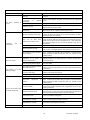
Table 4: Oil Lines
Copper Tubing Oil Line Length (Feet)
Lift
(Feet)
Single-Pipe OD
Two-Pipe OD
3/8”
1/2”
3/8”
1/2”
0
53
100
68
100
1
49
100
65
100
2
45
100
63
100
3
41
100
60
100
4
37
100
58
100
5
33
100
55
100
6
29
100
53
100
7
25
99
50
100
8
21
83
48
100
9
17
68
45
100
10
13
52
42
100
12
---
---
37
100
14
---
---
32
100
16
---
---
27
100
18
---
---
22
88
In retrofit applications, where an existing
oil line system is in place, a vacuum
check will help determine the efficacy of
the existing oil line system The vacuum
in a system should not exceed 6” Hg. for
a single pipe system, nor 12” Hg. for a
two-pipe system.
NOTE: The oil burner requires the use of
a bypass plug when converting from
single-pipe to two-pipe oil piping
systems. See burner manufacturer’s
instructions.
All fuel systems should include an oil
filter between the fuel oil storage tank
and the oil burner. For best results,
install the oil filter as close to the burner
as possible. When using an indoor oil
tank, the oil filter may be installed at the
tank downstream from the shut-off valve.
If firing the furnace under the 0.65 gph
rate, a 7 to 10 micron line filter should be
installed as close to the oil burner as
possible.
ELECTRICAL CONNECTIONS
The furnace is listed by the Canadian
Standards Association (CSA). It is
factory wired and requires minimal field
wiring. In the United States, the wiring
must be in accordance with the National
Fire Protection Association NFPA-70,
National Electrical Code, and with local
codes and regulations. In Canada, all
field wiring should conform to CAN/CSA
C22.1 Canadian Electrical Code, Part 1,
and by local codes, where they prevail.
The furnace should be wired to a
separate and dedicated circuit in the
7
30318 R4 9/9/2005
main
electrical
panel;
however,
accessory equipment such as electronic
air cleaners and humidifiers may be
included on the furnace circuit. Although
a suitably located circuit breaker can be
used as a service switch, a separate
service switch is advisable. The service
switch is necessary if reaching the circuit
breaker involves becoming close to the
furnace, or if the furnace is located
between the circuit breaker and the
means of entry to the furnace room. The
furnace switch (service switch) should be
clearly marked, installed in an easily
accessible area between the furnace and
furnace room entry, and be located in
such a manner to reduce the likelihood
that it would be mistaken as a light
switch or similar device.
The power requirements for all models:
120 VAC, 1 ∅, 60 Hz., 12A.
Accessories requiring 120 VAC power
sources such as electronic air cleaners
and humidifier transformers may be
powered from the ST9103 EFT. Do not
use the direct drive motor connections as
a power source, since there is a high risk
of damaging the accessories by
exposure to high voltage from the autogenerating windings of the direct drive
motor.
Thermostat wiring connections and air
conditioning contactor low voltage
connections are shown in the wiring
diagrams.
Some
micro-electronic
thermostats require additional controls
and wiring. Refer to the thermostat
manufacturer's instructions.
The thermostat should be located
approximately 5 feet above the floor, on
an inside wall where there is good
natural air circulation, and where the
thermostat will be exposed to average
room temperatures. Avoid locations
where the thermostat will be exposed to
cold drafts, heat from nearby lamps and
appliances, exposure to sunlight, heat
from inside wall stacks, etc.
Normal heat anticipator setting: 0.1 A.
For more precise adjustment, the heat
anticipator may be adjusted to the
amperage draw of the heating control
circuit as measured between the "R" and
"W" terminals of the thermostat. To
reduce the risk of damaging the heat
anticipator, do not measure circuit
without first removing one of the two
wires first. To determine the heating
circuit amperage draw:
1.
Disconnect one of the “R” or “W”
wires from the thermostat terminal.
2.
Connect an ammeter between the
wire and the thermostat terminal to
which it was attached.
3.
Note the amperage reading when
the heating contacts are closed.
(System switch must be on “HEAT” if
so equipped.
4.
Re-connect the thermostat wire. If
the thermostat is serving a
combination
heating
and
air
conditioning system, pay particular
attention to polarity.
5.
If the limit control opens with the United
Technologies 1158-120 electronic fan
control, the circulating fan will be
energized as well. When the limit closes,
the control initiates a two minute delay.
When this delay is finished, the fan off
timer will begin. At the end of the fan off
time cycle the burner will be energized,
initiating a normal burner cycle.
TABLE 5
Honeywell ST9103
Dip Switch
Position
When the thermostat is reconnected
and re-plumbed, adjust the heat
anticipator setting to match the
observed amperage reading.
FAN TIMER BOARD AND LIMIT
CONTROL
The Electronic Fan Timer integrates
control of all burner and circulator fan
operations. This control is the central
wiring point for most of the electrical
components in the furnace. The
Honeywell ST9103 has a fixed fan delay
on time of 30 seconds after the burner
ignites. The United Technologies 1158120 has an adjustable fan on time that is
set
by
selecting
the
dipswitch
combination displayed in Table 6. This
fan on delay can be set at 30, 60, 90 or
120 seconds. This provides a delay
between the burner ignition and blower
start-up to eliminate excessive flow of
cold air when the blower comes on. The
Honeywell ST9103 has an adjustable
fan off time of 60, 90, 120 and 150
seconds that is set by selecting a
dipswitch combination on the control
board displayed in Table 5. Similarly the
United Technologies 1158-120 have an
adjustable fan off time of 2, 3, 4 or 6
minutes displayed in Table 6. The fan off
delay time starts when the burner motor
is de-energized at the end of a call for
heat. Blower shutdown is delayed to
remove any residual heat from the heat
exchanger and improve the annual
efficiency of the furnace.
The electronic fan timer board works in
conjunction with snap disc limit controls,
which perform a safety function, and
breaks power to the oil burner primary
control, which shuts off the burner if the
furnace over-heats. The limit control is
thermally operated and automatically
resets. The limit control is factory
installed, pre-set and is not adjustable.
If a limit control opens, the Honeywell
ST9103 will energize the circulating fan.
When the limit control closes the burner
is re-energized and the heating cycle
begins again.
8
1
2
On
On
Blower Off Delay
Time
60 seconds
On
Off
90 seconds
Off
On
120 seconds
Off
Off
150 seconds
TABLE 6
United Technologies 1158-120
Dip Switch
Position
3
Blower Delay
Times
1
2
4
On
Seconds
Off
Off
30
On
Off
60
Off
On
90
On
On
Off
Minutes
120
Off
Off
2
On
Off
3
Off
On
4
On
On
6
Note: It is advisable not to set the
fan on delay time for a time period
longer than 90 seconds at highest
input. Longer fan on delay times
may result in nuisance limit trips.
CIRCULATING AIR BLOWER
All WML-C AND MPL-B furnace models
are equipped with a direct drive blower
system. Direct drive blower speed
adjustments are not normally required in
properly sized extended plenum duct
systems. The motor RPM and air CFM
delivery will vary automatically to
accommodate conditions within the usual
range of external static pressures typical
of residential duct systems. Under-sized
duct systems may require a higher
blower speed to obtain a reasonable
system temperature rise. Some older
duct systems were not designed to
provide static pressure. They typically
feature special reducing fittings at each
branch run and lack block ends on the
30318 R4 9/9/2005
trunk ducts. These systems may require
modification to provide some resistance
to the airflow to prevent over-amping of
the direct drive blower motor. Selecting a
lower blower speed may correct this
problem.
Direct drive blower speeds are adjusted
by changing the "hot" wires to the motor
winding connections. Please refer to
wiring diagram in Appendix B or the
wiring diagram label affixed to the
furnace.
THE
NEUTRAL
WIRE
(normally the white wire) IS NEVER
MOVED TO ADJUST THE BLOWER
SPEED.
DO NOT CONNECT POWER LEADS
BETWEEN MOTOR SPEEDS. THE
NEUTRAL WIRE MUST ALWAYS BE
CONNECTED TO THE MOTOR'S
DESIGNATED NEUTRAL TERMINAL.
It is possible and acceptable to use a
single blower speed for both heating and
cooling modes. The simplest method to
connect the wiring from both modes is to
use
a
"piggy-back
connector"
accommodating both wires on a single
motor tap. It is also acceptable to
connect the selected motor speed with a
pigtail joined to both heating and cooling
speed wires with a wire nut. As a safety
precaution
against
accidental
disconnection of the wires by vibration, it
is advisable to secure the wire nut and
wires with a few wraps of electricians
tape.
If the joining of the blower speed
wiring is done in the furnace junction
box, tape off both ends of the unused
wire.
DISCONNECT THE POWER SUPPLY
TO
THE
FURNACE
BEFORE
OPENING THE BLOWER ACCESS
DOOR TO SERVICE THE AIR FILTER,
FAN AND MOTOR. FAILURE TO
SHUT OFF POWER COULD ALLOW
THE
BLOWER
TO
START
UNEXPECTEDLY, CREATING A RISK
OF DEATH OR PERSONAL INJURY.
Do not use the blower speed wires as
a source of power to accessories as
electronic air cleaners and humidifier
transformers. The unused motor taps
auto-generate
sufficiently
high
voltages
to
damage
accessory
equipment.
Use
the
terminals
provided on the electronic fan timer.
Do not start the burner or blower fan
unless the blower access door is
securely in place.
Additional ST9103 Fan Timer Control
information is in Appendix A, Tables, and
in Appendix B, Wiring Diagrams.
HUMIDIFIER
A humidifier is an optional accessory
available through most heating supplies
outlets. Installation should be carried out
in accordance with the humidifier
manufacturer's installation instructions.
Water or water droplets from the
humidifier should not be allowed to come
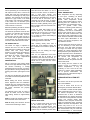
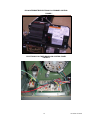
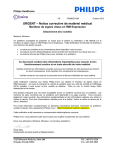
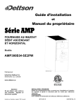
Figure 4: Horizontal Smoke Test Port Location
into contact with the furnace heat
exchanger. Do not use direct drive motor
connections as a source of power for
120 VAC humidifiers and humidifier
transformers.
OIL BURNER
The oil burner must align properly with
the cerafelt fiber chamber (firepot). The
cerafelt fiber chamber is initially quite
soft, but hardens and becomes quite
brittle after the first firing. The firepot is
held in place by a retaining bracket;
however, it is possible for the firepot to
shift if subjected to rough handling during
transit.
BEFORE
OPERATING
THE
FURNACE
CHECK
BURNER
ALIGNMENT WITH COMBUSTION
CHAMBER. THE END CONE OF THE
AIR TUBE MUST BE CENTRED TO
THE
ACCOMODATING
RING
PROVIDED IN THE DESIGN OF THE
COMBUSTION CHAMBER. ADJUST
ALIGNMENT
AS
NECESSARY
BEFORE THE FIRST FIRING.
OIL BURNER NOZZLES
WML-C AND MPL-B furnaces are
certified for multiple firing rates, ranging
from approximately 58,000 to 85,600
BTU/hr. on the WML-C and 85,500 to
123,000 BTU/Hr. on the MPL-B By
changing the oil burner nozzle within the
specific model range, and temperature
rise, the furnace may be fired at an ideal
rate for a wide range of structures.
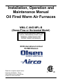
Figure 5: Vertical Smoke Test Port Location
9
30318 R4 9/9/2005
BURNER ELECTRODES
PROCEDURE:
Correct positioning of the electrode tips
with respect to each other, to the fuel oil
nozzle, and to the rest of the burners is
essential for smooth light ups and proper
operation. The electrode tips should be
adjusted to a gap of 5/32”, 1/16” ahead
of the nozzle, 5/16” above the centerline
of the nozzle. The “Z” dimension (front
edge of the burner head to the front face
of the nozzle is 1-1/8 inches.
Start the burner and allow it to run at
least ten minutes. Set the air shutter to
give a good flame visually. The
combustion air supply to the burner is
controlled by manipulating the air shutter
on the left side of the burner, and, if
necessary, the bulk air band. To adjust,
loosen the bolt on the movable shutter.
Move the shutter gradually until a good
flame (visually) has been achieved. Resnug the bolt.
Electrode positioning should be checked
before the first firing of the furnace.
The electrode porcelains should be free
of cracks, the electrode tips should be
tapered and free of burrs, and the
contact rods must be clean and be in
firm contact with the ignition transformer
contact springs. The electrodes must not
come into contact with the burner head.
OIL BURNER SET-UP
The burner air supply is adjusted to
maintain the fuel to air ratio to obtain
ideal combustion conditions. A lack of air
causes "soft" and "sooty" flames,
resulting in soot build-up throughout the
heat exchanger passages. Excess
combustion air causes a bright roaring
fire and high stack temperatures
resulting in poor fuel efficiency.
PREPARATIONS:
Drill a ¼” test port in the venting, ideally
at least 2 flue pipe diameters away from
the furnace breeching, if venting
horizontally from the furnace, or from the
flue pipe elbow if venting vertically before
reaching the furnace. (See Figures 4 and
5).
Check the initial draft setting as the
furnace warms up. The draft may be
measured at the test port. The breech
draft should be approximately - 0.05”
w.c. to obtain an over fire draft reading of
- 0.02 inches w.c.
Check the oil pump pressure. Standard
operating pressure is 100 PSIG.
After reaching steady state, take a
smoke test. If not indicating a trace, set
the combustion air controls to provide a
trace.
Typically, the CO2 reading will range
from 11.5% to 13.5%.
After the air adjustments have been
completed, and the air shutter or air
adjustment plate has been secured, recheck the over fire draft and take another
smoke test to ensure that the values
have not changed.
The test port will allow flue gas samples
to be taken and stack temperatures to be
measured.
Stack temperature will vary depending
on fuel input, circulating air blower
speed, and burner set up, etc. In
general, stack temperature should
typically range between 380°F to 550°F,
assuming that the combustion air is
approximately room temperature (65°F 70°F).
In
general,
lower
stack
temperature indicates greater efficiency;
however,
excessively
low
stack
temperature can lead to condensation
forming in the chimney and / or venting.
Sulphur and similar contaminants in the
fuel oil will mix with condensation to form
acids. Acids and resultant chemical salts
will cause rapid deterioration of the
chimney and venting components, and
may attack the furnace.
If the flue gases are below the range, it
may be necessary to slow down the
blower fan. If the flue gases are above
the range, the blower fan may require
speeding up. Stack temperature varies
directly with the system temperature rise.
System temperature rise is the difference
between the furnace outlet temperature
and furnace inlet temperature as
measured in the vicinity of the
connection between the plenum take-offs
and the trunk ducts.
If the venting from the furnace to the
chimney is long, or exposed to cold
ambient temperatures, it may be
necessary to use L-Vent as the vent
connector to reduce stack temperature
loss to prevent condensation. The
venting should be inspected annually to
ensure that it is intact.
The furnace must be set up as the final
step in the installation.
A) The oil burner must be set up
following the procedures outlined above.
The Beckett burner bulk air band is
should be closed, and the air shutter
initial setting should be approximately
7.00.
Note B: Ideally, hole should be at least
12 inches from breeching or elbow.
STACK TEMPERATURE:
FURNACE INSTALLATION SETUP
Before starting the burner, check the
burner alignment with the combustion
chamber (fire pot), check that the correct
nozzle is tightened into place, and that
the burner electrodes are properly
positioned.
Note A: Locate hole at least 6 inches on
the furnace side of the draft control.
excess air, or contaminated fuel. Do not
ignore this indicator.
Figure 6: Checking Over-Fire Draft.
SMOKE TEST NOTE:
If oily or yellow smoke spots are found
on the smoke test filter paper, it is
usually a sign of unburned fuel. This
indicates poor combustion. This type of
problem may be caused by excess draft,
10
B) The WML-C models should operate
within a temperature rise of 45°F to 75°F.
The MPL-B temperature rise range
should be 50°F to 80°F. To determine
the temperature rise, measure the supply
air and return air temperatures when the
furnace has reached steady state
conditions. This is the point at which the
supply air temperature stops increasing
relative to the return air temperature. The
furnace may have to run 10 to 15
minutes to reach steady state conditions.
The measurements may be made with
duct thermometers or thermocouples
30318 R4 9/9/2005
used in conjunction with multi-meters
with
temperature
measurement
capabilities.
anywhere within the heating system
which may cause some concern or
annoyance to the home owner, etc.
The return air should be measured at a
point where the thermometer will be well
within the air stream near the furnace
return air inlet. Actual location is not
particularly critical; however, avoid
locations
where
the
temperature
readings could be affected by humidifier
bypass ducts, the inside radius of
elbows, etc.
F) Be sure that the homeowner is
familiar
with
the
furnace.
The
homeowner should be aware of the
location of electrical circuit breaker or
fuse, the location of any electrical
switches controlling the furnace, the
location of the oil tank shut-off valve and
how to operate the valve. The
homeowner should be informed where
the oil tank gauge is located and how to
read it.
The supply air temperature should be
measured at a point where the
thermometer will be well within the air
stream near the furnace supply air outlet.
Usually, the side mid-point of the supply
air plenum take-off is ideal, providing it is
out of the line of sight to the heat
exchanger. If the thermometer is within
the line of sight of the heat exchanger,
the supply air readings may be skewed
by radiant heat from the heat exchanger.
If the plenum take-off is unsuitable, the
supply air temperature may be measured
within the first 18 inches of the first
segment of supply air trunk duct.
If the temperature rise is outside the
recommended range, it may be adjusted
on direct drive equipped units by
selecting alternate circulation fan motor
speeds. If the temperature rise is too
high, speed the fan up. If the
temperature rise is too low, slow the fan
down.
It would be beneficial to review safety
issues with the home owner, such as the
danger of storing combustibles too close
to the furnace, hanging anything on the
furnace vent pipe, and especially the
dangers of indiscriminately pressing the
burner reset button.
IMPORTANT: Be sure that the home
owner knows where the burner reset
switch is located, and is aware that the
reset switch is not to be activated more
than once without a thorough look for the
cause of the problem, (lack of fuel, etc.).
Be sure that the homeowner knows
when to quit trying to start the furnace
during these conditions and who to call
for emergency service.
MAINTENANCE AND SERVICE
A: Routine Maintenance By Home
Owner
C) Keep in mind that the stack
temperature varies directly with the
temperature rise. The higher the
temperature rise, the higher the stack
temperature will be, resulting in lower
efficiency. The lower the temperature
rise, the lower the stack temperature will
be, which, in some cases, may allow
condensation to form in the chimney and
other vent parts.
Other than remembering to arrange for
the annual professional servicing of the
furnace by the service or installation
contractor, the most important routine
service performed by the homeowner is
to maintain the air filter or filters. A dirty
filter can cause the furnace to over-heat,
fail to maintain indoor temperature during
cold weather, increase fuel consumption
and cause component failure.
D) Test the high limit control to ensure
that it is operating correctly. This may be
done by temporarily removing the
circulator fan heating wire or neutral
wire. Turn of electrical power to the
furnace before working with the motor
wires. Be sure to protect any removed
wires from shorting out on metal furnace
parts. If the high limit test is successful,
shut off the electrical power to the
furnace, restore the proper motor wiring.
Finally, restore power to the furnace.
The furnace filter(s) should be inspected,
cleaned or replaced monthly. The
furnace is factory equipped with a semipermanent type filter. If the filter is
damaged, replace with filters of the same
size and type.
E) Operate the furnace through a
minimum of three full heating cycles.
During this time, check for fuel oil leaks,
gross air leakage from the supply air
ductwork, unusual noises originating
During the routine service, inspect the
general condition of the furnace watching
for signs of oil leaks in the vicinity of the
oil burner, soot forming on any external
part of the furnace, soot forming around
the joints in the vent pipe, etc. If any of
these conditions are present, please
advice your service or installation
contractor.
11
B: Annual Service By Contractor
THE
COMBUSTION
CHAMBER
(FIREPOT) IS FRAGILE. USE CARE
WHEN INSPECTING AND CLEANING
THIS AREA.
The heat exchanger should be inspected
periodically and cleaned if necessary. If
cleaning is necessary, SHUT OFF
POWER TO THE FURNACE and
remove the burner. Using a stiff brush
with a wire handle, brush off scale and
soot from inside the drum and flue pipe.
To clean the radiator, remove the round
cover or covers on the inner radiator
access pipes located on the front panel
between the oil burner and the flue pipe.
Rear breech models have a single front
cleanout and front breech models have
two front cleanouts.
A wire brush can be used to loosen dirt
and debris on the inside surfaces of the
radiator. Clean out all accumulated dirt,
soot and debris with a wire handled
brush and an industrial vacuum cleaner.
Replace the clean-out covers.
Most circulating fan motors are
permanently lubricated by the motor
manufacturer. These motors will have no
oil ports. If the blower motor does
contain oil ports, under normal operating
conditions it will not require oiling for the
first two years. Oil sparingly; a few drops
in each oil port with SAE 20 nondetergent oil. Oiling is most easily done
with a "tele-spout" oiler. This oiler has a
long flexible plastic spout. DO NOT
OVER-LUBRICATE. Excess oil may
result in premature electric motor failure.
Inspect the blower fan. Clean it if
necessary.
Oil Burner Maintenance: Follow the
instructions
of
the
oil
burner
manufacturer.
(See
oil
burner
manufacturer's instructions supplied with
furnace). The oil burner nozzle should be
replaced annually. We recommend that
the oil filter be changed on an annual
basis.
The venting system should be cleaned
and inspected for signs of deterioration.
Replace pitted or perforated vent pipe
and fittings. The barometric draft
regulator should open and close freely.
All electrical connections should be
checked to ensure tight connections.
Safety controls such as the high limit
controls
should
be
tested
for
functionality. The fan control functions
30318 R4 9/9/2005
should be checked to ensure that all fan
speeds are operating properly.
OPERATING INSTRUCTIONS
Before Lighting
Open all supply and return air registers
and grilles.
Open all valves in oil pipes.
Turn on electric power supply
To Light Unit
Set the thermostat above room
temperature to call for heat. The burner
should start. NOTE: It may be necessary
to press the RESET button on the
primary combustion control relay.
There will be a fan on time delay before
the circulating fan is energized. The
Honeywell ST9103 has a fixed fan delay
on time of 30 seconds after the burner
ignites. The United Technologies 1158120 has an adjustable fan on time that is
set
by
selecting
the
dipswitch
combination displayed in Chart 1. This
fan on delay can be set at 30, 60, 90 or
120 seconds.
Set the thermostat below room
temperature. The oil burner should stop.
The air circulation blower will continue to
run until the time off setting selected on
the electronic fan timer control times out.
The Honeywell ST9103 has an
adjustable fan off time of 60, 90, 120 and
150 seconds that is set by selecting a
dipswitch combination on the control
board.
Similarly
the
United
Technologies
1158-120
has
an
adjustable fan off time of 2, 3, 4 or 6
minutes
The
fan
timer
control
adjustments may be altered if the air at
the room registers is uncomfortably high
upon blower start up or shutdown.
furnace and set the thermostat above
room temperature. After three or four
minutes of burner operation, the limit
control should turn the burner off. When
the limit function test is complete, shut
off electrical power to the furnace,
replace the neutral wire to the blower fan
motor, and then restore power. The
blower fan will start up immediately.
Once the temperature has dropped and
the limit control has reset, the fan will
operate until the fan off time is achieved.
The oil burner will then resume operation
and continue until the thermostat is
satisfied. Restore the thermostat setting
to a comfortable temperature.
To Shut Down Unit
Set the thermostat to the lowest possible
setting.
Set the manual switch (if installed) in the
Electrical Power Supply Line to "OFF".
NOTE: If the furnace is to be shut down
for an extended period of time, close the
oil supply valve to the oil burner.
DO NOT ATTEMPT TO START THE
BURNER WHEN EXCESS OIL HAS
ACCUMULATED,
WHEN
THE
FURNACE IS FULL OF VAPOUR, OR
WHEN THE COMBUSTION CHAMBER
IS VERY HOT. NEVER BURN
GARBAGE OR PAPER IN THE
FURNACE, AND NEVER LEAVE
PAPER OR RAGS AROUND THE UNIT.
The necessary adjustments to the fan
control settings should be determined by
measuring the temperature of the air in
the supply air take-off, or within the first
few inches of the supply air trunk. The
side mid point of the transition is usually
ideal, providing that the thermometer
probe is beyond the "line of sight"
wherein false readings from radiant heat
could be observed. The system
temperature rise, the difference in
temperature between the supply air and
return air, should be within the indicated
range on the appliance rating plate.
To check the operation of the limit
switch, shut off power to the furnace.
Temporarily remove the neutral wire
from the direct drive blower motor.
Restore the electrical power to the
12
30318 R4 9/9/2005
APPENDIX A- WML-C AND MPL-B BURNER SET UP
WML-C AND MPL-B furnaces may be used with the following oil burners.
Please note: The Beckett AF, and Riello 40F oil burners are for applications using indoor air for combustion only. For sidewall
venting applications utilizing outdoor air for combustion, use the Beckett AFII or the Riello 40BF (Balanced Flue) oil burners
only.
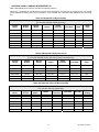
Table A-1 Beckett AF Oil Burner Set-Up
Beckett AF Series Oil Burners
(For use with chimney vented units only)
1
Furnace
Model
Output
BTU/Hr
Burner
Model
Nozzle
Pump
Pressure
Flow Rate
Head 1
Static
Plate
WML-60C 2
58,000
AF76BNHS
0.50 / 80°A
100 PSIG
0.50 USGPH
F3
3- ⅜ in.
WML-80C
75,000
AF76BNHS
0.65 / 80°A
100 PSIG
0.65 USGPH
F3
3- ⅜ in.
WML-90C
85,600
AF76BNHS
0.75 / 80°A
100 PSIG
0.75 USGPH
F3
3- ⅜ in.
MPL-90B
85,500
AF76XN
0.75 / 80°A
100 PSIG
0.75 USGPH
F3
2- ¾ in.
MPL-100B
96,000
AF76XN
0.85 / 80°A
100 PSIG
0.85 USGPH
F3
2- ¾ in.
MPL-120B
112,000
AF76XN
1.00 / 60°A
100 PSIG
1.00 USGPH
F3
2- ¾ in.
MPL-130B
123,000
AF76YB
1.10 / 70°A
100 PSIG
1.10 USGPH
F6
Head is shielded by ceramic insulator. 2 Low Firing Rate Baffle required when using a 0.50-gallon nozzle.
2- ¾ in.
Table A-2 Beckett AFII Oil Burner Set-Up
Beckett AFII Series Oil Burners
(For use with sidewall vented units using outdoor combustion air)
Furnace
Model
Output
BTU/Hr
Burner
Model
Nozzle
Pump
Pressure
Flow Rate
Head
WML-60CB2
63,500
AFII-85
0.50 / 60°A
145 PSIG
0.55 USGPH
FB0
WML-80CB2
75,000
AFII-85
0.60 / 60°A
145 PSIG
0.65 USGPH
FB3
WML-90CB2
85,600
AFII-85
0.70 / 60°A
145 PSIG
0.75 USGPH
FB3
MPL-90BB2
85,500
AFII-150
0.70 / 60°A
145 PSIG
0.75 USGPH
FB0
MPL-100BB2
96,000
AFII-150
0.80 / 60°A
145 PSIG
0.85 USGPH
FB3
MPL-120BB2
112,000
AFII-150
0.85 / 70°A
145 PSIG
1.00 USGPH
FB3
Table A-3 Riello 40F Series Oil Burner Set-Up
Riello 40F Series Oil Burners
(For use with chimney vented units)
Furnace
Model
Output
BTU/Hr
Burner
Model
Nozzle
Pump
Pressure
Flow Rate
Air Gate
Turbulator
Setting
WML-60CRF
59,500
40F3
0.50 / 60°W
105 PSIG
0.51 USGPH
2.6
1.0
WML-80CRF
75,000
40F3
0.60 / 60°W
115 PSIG
0.65 USGPH
2.6
1.5
WML-90CRF
85,600
40F3
0.65 / 60°W
135 PSIG
0.75 USGPH
3.6
2.0
MPL-90BRF
85,500
40F5
0.60 / 60°W
145 PSIG
0.75 USGPH
2.25
0.0
MPL-100BRF
96,000
40F5
0.65 / 60°W
145 PSIG
0.85 USGPH
2.5
0.5
MPL-120BRF
112,000
40F5
0.85 / 60°W
145 PSIG
1.00 USGPH
2.75
1.0
13
30318 R4 9/9/2005
Table A-4 Riello Balanced Flue (BF) Burner Set-Up
Riello Balanced Flue Series Oil Burners
(For use with sidewall vented units using outdoor combustion air)
Furnace
Model
Output
BTU/Hr
Burner
Model
Nozzle
Pump
Pressure
Flow Rate
Turbulator
Setting
WML-60CRB
59,500
40BF3
0.50 / 60°W
105 PSIG
0.51 USGPH
1.0
WML-80CRB
75,000
40BF3
0.60 / 60°W
115 PSIG
0.65 USGPH
1.5
WML-90CRB
85,600
40BF3
0.65 / 60°W
135 PSIG
0.75 USGPH
NOTE: Air gate setting may vary for sidewall vented units where air gate must be adjusted to achieve zero smoke.
A.1 OIL BURNER AIR
ADJUSTMENT
For complete details, consult the oil
burner instruction manual provided in
the furnace documents envelope.
Beckett AF Burner
Adjust the air shutter by loosening the
locking screws and moving the air
shutter, and if necessary, the bulk air
band.
Beckett AFII Burner
Adjust the burner air supply by first
loosening the locking screw located on
the black dial to the right of the burner.
Turn the black dial clockwise to
increase the combustion air and
counter-clockwise to decrease the
combustion air. Re-tighten the locking
screw after obtaining the proper setting.
Riello 40 Series (Chimney Vented)
Riello burners are factory set with
respect to nozzle size; pump pressure,
air gate and turbulator adjustments for
each model and firing rate. By
removing the burner cover and
loosening the screws that secure the
air adjustment plate, the combustion air
can be adjusted. Move the adjusting
plate to either increase or decrease
combustion air. When the proper air
setting is achieved, retighten the fixing
screws.
Riello Balanced Flue (BF) Series
Riello burners are factory set with
respect to nozzle size; pump pressure,
and turbulator adjustments for each
model and firing rate. The combustion
air can be adjusted with the burner
cover on by first removing the plastic
cover on the top right hand side of the
burner cover. With a Philips head
screw driver, turn the adjustment screw
clockwise to increase combustion air or
counter-clockwise
to
decrease
combustion air. When the combustion
air is set, re-insert the plastic cover.
A.2 BURNER ELECTRODES
Adjustment of the electrode tips with
respect to each other, the nozzle, and
to the rest of the burner is very
important to ensure smooth start-ups
and to permit efficient combustion.
Beckett AF Burner
Electrode gap: 5/32 inch.
Distance above horizontal centerline:
5/16 inch. Older instruction sheets
specify 7/16 inch. The current
specification is 5/16 inch.
Distance ahead of nozzle: 1/16 inch.
“Z” dimension, the distance from the
front of the end cone (head) to the face
of the nozzle should be 1-1/8 inches. If
a ceramic head is used, the distance
from the end cone to the nozzle face is
increased to 1-3/8 inches.
Riello 40F, & BF Burners
Electrode gap: 5/32 inch.
Distance above horizontal centerline:
13/64 inch.
Distance ahead of nozzle: 5/64 to 7/64
inch.
A.3 START UP
The furnace should be operated for a
minimum of 15 minutes to reach steady
state conditions before fine tuning
combustion. The warm up time is ideal
for testing the oil pump pressure.
Drill a 1/4-inch test port in the venting
between the furnace flue outlet and
draft regulator (barometric damper).
Insert a stack thermometer and note
the flue gas temperature. The flue
gases should be within a range of
350°F to 450°F. If the flue gases are
below the range, it may be necessary
to slow down the blower fan. If the flue
gases are above the range, the blower
fan may require speeding up. Stack
temperature varies directly with the
14
2.0
system temperature rise. System
temperature rise is the difference
between the furnace outlet temperature
and furnace inlet temperature as
measured in the vicinity of the
connection between the plenum takeoffs and the trunk ducts
Perform a smoke spot test. The smoke
spot should not exceed No. 1 on the
Bacharach Scale.
After the air adjustments have been
completed, re-check the draft pressure
at the test port on the burner mounting
plate as shown in Figure #6. The draft
should be adjusted to 0.02 inches w.c.
In the United States, the Beckett AF
Burner may be equipped with Beckett's
"Inlet Air Shut-Off" to increase
efficiency. (Beckett Part No. AF/A
5861).
NOTE: USE OF THE INLET AIR
SHUT-OFF COULD CAUSE POST
COMBUSTION NOZZLE DRIP.
A.4 SPECIAL INSTRUCTIONS
FOR UNITS EQUIPPED WITH
RIELLO BURNERS
Riello burners are factory set with
respect to nozzle size, pump pressure,
air gate and turbulator adjustments for
each model and firing rate; therefore,
do not use the above listed set up
procedures.
Riello specifications are listed in Tables
A-3 and A-4. Consult the Riello
Installation Instructions supplied with
the Burner for specific information
concerning
burner
adjustments,
operation,
and
trouble-shooting.
30318 R4 9/9/2005
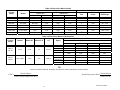
Table A-6 Direct Drive Blower Set-Up
Blower Set-Up
Cooling Capacity
Furnace
Model
Blower
WML-60C
GT10 DD
Low
½ HP
Med-Low
½ HP
3
½ HP
763 – 1505
WML-80C
GT10 DD
Med-Low
½ HP
Med-High
½ HP
3
½ HP
763 – 1505
WML-90C
GT10 DD
Med-High
½ HP
High
½ HP
3
½ HP
763 – 1505
MPL-90B
GT12-10DD
Low
¾ HP
Med-High
¾ HP
3
¾ HP
1185 – 1553
MPL-100B
GT12-10DD
Med-High
¾ HP
High
¾ HP
3
¾ HP
1185 – 1553
¾ HP
1185 – 1553
¾ HP
1185 – 1553
0.20 in. w.c.
Speed
0.50 in. w.c.
Motor
Speed
Tons
Motor
MPL-120B
GT12-10DD
High
¾ HP
High
¾ HP
3
MPL-130B
GT12-10DD
High
¾ HP
High
¾ HP
3
Power
CFM Range
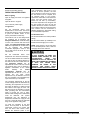
Table A-8 Direct Drive Blower Characteristics
Furnace
Model
WML-C
60 - 90
MPL-B
90-130
CFM
Blower
Motor HP
Motor FLA
∆T
Speed
External Static Pressure – Inches w.c.
0.20
GT10
GT12-10DD
½ HP
¾ HP
7.0
45-75°F
12.5
50-80°F
0.30
0.40
0.50
LOW
813
813
797
763
MED-LOW
1170
1144
1118
1063
MED-HIGH
1423
1381
1291
1220
HIGH
1505
1444
1359
1291
LOW
1334
1286
1239
1185
MED-LOW
1389
1332
1287
1236
MED-HIGH
1423
1373
1326
1289
HIGH
1553
1491
1449
1331
TIP:
These Formulae will assist with the design of the ductwork and the determination of airflow delivery:
CFM =
Bonnet Output
SystemTemperature Rise =
(1.085 x SystemTemperature Rise)
15
Bonnet Output
(1.085 x CFM )
30318 R4 9/9/2005
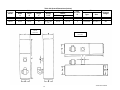
Table A-9 General Dimensions (Inches)
Plenum Openings
Cabinet
Filter
Width
A
Depth
B
Height
C
Supply
DxE
Side
Bottom
Flue
Diameter
H
WML-C
22
22-1/8
55-1/4
19 x 19
18 x 18
18 x 18
5
Permanent
20 x 20 x 1
265
MPL-B
22-1/4
22-1/4
62
20-1/2 x 201/2
18 x 18
18 x 18
6
Permanent
20 x 20 x 1
292
Furnace
Model
WML-C &
MPL-B
Down flow
Return
Type
Size
Shipping
Weight
WML-C & MPL-B
Horizontal
16
30318 R4 9/9/2005
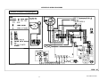
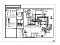
APPENDIX B: WIRING DIAGRAMS
Beckett AF Burner Wiring Diagram
17
30318 R4 9/9/2005
Beckett AFII Burner Wiring Diagram
18
30318 R4 9/9/2005
Riello 40F3 and F5 Burner Wiring Diagram
19
30318 R4 9/9/2005
Riello 40BF3 Burner Wiring Diagram
20
30318 R4 9/9/2005
OPERATION OF OIL BURNER
Once the furnace flue pipe, electrical
and oil line connections have been
made, use the following instructions to
set the burner:
Shut off the electrical power to the
furnace.
Install an oil pressure gauge to the
pressure port on the oil pump. (Refer to
the oil pump specification sheet
included with the burner instructions).
Restore electrical power to the furnace.
Start the furnace and bleed all air from
the fuel oil lines.
Close the purge valve and fire the unit.
Allow the furnace to warm up to normal
operating temperatures. During this
time, set the pump pressure in
accordance with the data provided in
Appendix A, Table A-2, and A-5.
When the furnace has reached "steady
state" (after approximately 15 minutes).
Set combustion air damper to get a
TRACE of smoke.
resume operation and continue until the
thermostat is satisfied. Restore the
thermostat setting to a comfortable
temperature.
Set the heat anticipator adjustment in
the thermostat (if so equipped), by
removing the "R" or "W" wire to the
thermostat, then reading the amperage
draw between the two wires. Failure to
remove one of the wires from the
thermostat while performing this test
could burn out
the heat anticipator.
Set the heat anticipator to the
amperage measured.
NOTE: THE FURNACE SHOULD BE
RUN THROUGH AT LEAST THREE
FULL CYCLES BEFORE LEAVING
THE INSTALLATION, TO ENSURE
THAT
ALL
CONTROLS
ARE
OPERATING PROPERLY AND AS
EXPECTED.
NOTE:
ALL JOINTS IN ANY
POSITIVE
PRESSURE
VENTING
SYSTEM MUST BE CHECKED FOR
LEAKS BEFORE LEAVING THE
INSTALLATION SITE.
Check the system temperature rise.
The temperature rise is the difference
between the return air temperature
measured at a point near the return air
inlet, and the supply air temperature
measured near the furnace outlet. If the
temperature rise is too high, the airflow
must be increased. If the temperature
rise is too low, the fan should be
slowed down.
Turn off the burner. Observing the duct
thermometer in the supply air stream,
note the temperature at which the
blower fan stops. The fan adjustments
can be made by moving the dipswitch
settings on the timer control board for
fan off delay.
To check the operation of the limit
switch, shut off power to the furnace.
Temporarily remove the neutral wire
from the direct drive blower motor.
Restore the electrical power to the
furnace and set the thermostat above
room temperature. After three or four
minutes of burner operation, the limit
control should turn the burner off.
When the limit function test is
complete, shut off electrical power to
the furnace, replace the neutral wire to
the blower fan motor, and then restore
power. The blower fan will start up
immediately. Once the temperature has
dropped and the limit control has reset,
the fan will operate until the fan off time
is achieved. The oil burner will then
21
30318 R4 9/9/2005
APPENDIX C-R7184 TROUBLESHOOTING
R7184 DETAILED SEQUENCE OF OPERATION (FIGURE 7)
Power is applied to unit. The R7184 completes a self-diagnostic procedure. If no light or flame is present, and unit
passes its self-diagnostic procedure, the control enters into the idle mode.
Thermostat calls for heat:
A) Safety check is made for flame (4 second delay).
1)
If flame is not present, the R7184 will apply power to the burner motor and igniter.
2)
If flame is present, the control remains in the idle state.
B) Unit enters a pre-purge period of 15 seconds.
C) After 10 seconds, control checks for flame presence.
1)
If flame is not present, the R7184 enters the trial for ignition state.
2)
When flame is present, the control enters lock out mode.
D) Control monitors the burner flame.
1)
When flame is present, the control enters ignition carryover state. (Continues to spark for 10 sec.).
a)
Provides continuous spark after flame is sensed to assure that burner remains lit.
b)
Turns on LED diagnostic light.
c)
Starts carryover timer.
(i)
Flame and call for heat are monitored.
•
If flame is lost and lockout timer has not expired, R7184 will return to trial for ignition state.
•
If flame is lost and lockout timer has expired, R7184 will enter the recycle state.
♦
Recycle timer starts.
♦
Burner motor and igniter and solenoid valve are turned off.
♦
LED diagnostic light flashes slowly.
E) Carryover timer expires.
1)
Enters run state.
a)
Igniter turns off.
Combustion continues until thermostat is satisfied, or R7184 detects a loss of flame and enters into Recycle Mode.
F)
Thermostat is satisfied - call for heat is terminated:
a)
R7184 shuts off burner motor and solenoid valve.
(i)
If control utilizes a blower motor off delay, after 30 seconds, flame presence is checked.
•
If flame is not present, the R7184 LED diagnostic light is off and returns to idle state.
•
If flame is presence is detected, the control enters lock out mode.
22
30318 R4 9/9/2005
R7184 INTERRUPTED ELECTRONIC OIL PRIMARY CONTROL
FIGURE 7
ELECTRONIC FAN TIMER BOARD ON CONTROL PANEL
FIGURE 8
23
30318 R4 9/9/2005
IDLE STATE
THERMOSTAT CALLS FOR HEAT
SAFETY CHECK FOR FLAME (5 SEC.)
R7184
SEQUENCE of
OPERATION
REMAINS IN IDLE STATE
NO FLAME
FLAME
BURNER MOTOR & IGNITOR START
10 SEC.
SAFETY CHECK FOR FLAME (5 SEC.)
NO FLAME
FLAME
SOLENOID VALVE OPENS
LOCKOUT STATE
TRIAL FOR IGNITION
•
•
•
•
BURNER FLAME MONITORED
NO FLAME
FLAME
•
•
•
CARRYOVER STATE
Provides continuous spark
LED diagnostic light ON
Start Carryover Timer
R7184:
Shuts off burner motor
Shuts off igniter
Shuts off Solenoid Valve
Fast Flashes LED Diagnostic
Light
FLAME LOST
TO EXIT LOCKOUT
PRESS RESET
FLAME
CARRYOVER TIMER EXPIRES
FLAME LOST
FLAME
•
RUN STATE
Igniter turns off.
FLAME LOST
RECYCLE TIMER STARTS
THERMOSTAT SATISFIED
•
•
•
R7184 SHUTS OFF:
Burner Motor
Solenoid Valve
LED Diagnostic Light
•
•
•
•
30 SEC.
R7184:
Shuts off Solenoid Valve
Shuts off Igniter
Shuts off Burner Motor
Slow Flashes LED
diagnostic light
SAFETY CHECK FOR FLAME (5 SEC.)
RECYCLE TIMER EXPIRES
(60 SECONDS
NO FLAME
FLAME
RETURNS TO IDLE STATE
24
30318 R4 9/9/2005
Table C-1: ELECTRONIC FAN TIMER BOARD (EFT) DETAILED SEQUENCE OF OPERATION
Mode
HEAT
Action
System Response
Thermostat calls for heat. ("W"
terminal is energized).
a. EFT closes oil primary control T - T connections).
b. Ignition system and R7184 oil primary control start the furnace. Oil flows as long as
the oil primary control senses flame.
c. Burner motor is energized and heat "fan on" delay timing begins. When timing is
complete, the circulator fan is energized at heat speed.
Thermostat ends call for heat.
("W" terminal is de-energized).
FAN
R7184 oil primary control is de-energized, terminating the burner cycle.
Heat "fan off" delay timing begins. Length of delay depends on EFT dipswitch
settings. When timing is complete, the circulator fan is de-energized.
c. EFT returns to standby mode, (Oil primary control and circulator fan are off, unless
continuous fan operation is selected at the thermostat).
a.
b.
c.
Oil primary control locks out within lockout timing, (30 seconds).
Burner motor is de-energized. (Even though thermostat is still calling for heat).
If circulator fan has started, it continues through the selected heat “fan off” delay
period.
Established flame fails.
a.
b.
Burner motor is de-energized and oil primary control goes into recycle mode.
If the selected heat “fan off” delay timing is longer than the recycle delay
timing, the circulator fan continues to run through the next trial for ignition.
Thermostat begins call for
cool. (G and Y terminals are
energized).
a. Cooling contactor is energized immediately.
b. Circulator fan is energized at cool speed.
Thermostat ends call for cool.
(G and Y terminals are deenergized).
a.
b.
Thermostat begins call for fan.
(G terminal is energized).
a. Circulator fan is energized immediately at cooling speed.
Thermostat ends call for fan.
(G terminal is de-energized).
a. Circulator fan is de-energized immediately.
Burner fails to light.
COOL
a.
b.
a.
b.
c.
Oil primary control shuts off burner.
Circulator fan is energized immediately at heat speed.
EFT opens oil primary control T - T connections. Circulating fan runs as long as
limit string stays open.
d. If there is a call for cooling or fan, the circulating fan switches from heating to
cooling speed.
Limit switch string opens.
LIMIT
Limit switch string closes
(with existing call for heat).
Limit switch string closes
(without existing call for heat).
FAN
Continuous circulating fan is
connected.
EAC
Electronic Air
connected.
HUM
Humidity control is connected.
Cleaner
Cooling contactor is de-energized immediately.
Circulator fan turns off immediately.
is
a.
b.
c.
d.
EFT begins heat “fan off” delay sequence.
Circulating fan turns off after the selected heat “fan off” timing.
EFT re-closes oil primary control T - T connections.
Oil primary control is energized, initiating burner light off.
a.
b.
Circulator fan turns off when heat “fan off” delay time is complete.
Normal operation resumes; EFT control is in standby mode awaiting next
thermostat command.
a. Circulating fan is energized when there is no call for heat, cool, or fan.
b. If fan operation is required by a call for heat, cool, or fan, the EFT switches off the
continuous fan speed tap before energizing the other fan speed.
•
Electronic air cleaner (EAC) connections are energized when the heat or cool
speed of the circulator fan is energized. EAC connections are not energized when
the optional continuous fan terminal is energized.
•
Humidifier connections are energized when the oil burner motor is energized.
25
30318 R4 9/9/2005
R7184 LED DIAGNOSTIC LIGHT
TROUBLESHOOTING
The LED diagnostic light has several
functions. It indicates the state or mode
in which the oil burner is operating. It will
also indicate fault conditions, and help
determine cad cell resistance while the
burner is operating.
IMPORTANT: Due to the potential
hazard of line voltage, only a trained,
experienced service technician should
perform the troubleshooting procedure.
NORMAL CONDITIONS:
Check the diagnostic light for indications
of burner condition. Refer to R7184 LED
DIAGNOSTIC LIGHT section for details.
The LED diagnostic light will turn on
when the burner enters the carryover
state; the point at which ignition spark is
on, and will remain on through the run
state, where the ignition spark is
terminated but the burner continues to
fire.
The LED diagnostic light will turn off at
the end of the burner cycle as the R7184
enters the idle state, and will remain off
until the next heating cycle.
FAULT CONDITIONS:
If the LED diagnostic light is flashing
quickly; 1 Hz (½ second on / ½ second
off), the R7184 is in the lockout state or
in restricted mode. To exit the lockout
state, press the reset button.
If the LED diagnostic light is flashing
slowly; ¼ Hz (2 seconds on / 2 seconds
off), the R7184 is in the recycle state.
This indicates that flame sensing was
lost after the lockout timer expired during
the ignition carryover state. The R7184
will return to the idle state within 60
seconds.
CAD CELL CONDITION:
If the LED diagnostic light is off, the cad
cell is not sensing flame.
If the LED diagnostic light is on, the cad
cell is sensing flame, or viewing ambient
light.
PRELIMINARY STEPS:
WHEN SIMULATING A CALL FOR
HEAT AT THE R7184, DISCONNECT
AT LEAST ONE THERMOSTAT LEAD
WIRE FROM THE T1 - T2 TERMINALS
TO PREVENT DAMAGE TO THE
THERMOSTAT. NEGLECTING THIS
PROCEDURE MAY BURN OUT THE
HEAT
ANTICIPATOR
OF
A
STANDARD 24 VAC THERMOSTAT,
OR CAUSE HARM TO COMPONENTS
WITHIN
A
MICRO-ELECTRONIC
THERMOSTAT.
2
Between 400 - 800
3
Between 800 – 1600
4
Between 1600- 5000
Refer to Table C-4 or C-5 for further
troubleshooting information.
•
Check the limit switches to
ensure that the switch contacts are
closed.
•
Check the electrode gap and
position.
•
Check the contacts between the
oil primary control and the electrodes.
•
Check oil supply (tank gauge).
•
Less than 400
Check for line voltage power on the oil
primary control black and white lead
wires.
•
Check the power supply; fuse
box or breaker, any service switches, all
wiring connections, and burner motor
reset button (if equipped).
TABLE C-2: CAD CELL RESISTANCE
1
PRELIMINARY CHECKS:
Before checking the oil primary control,
perform these preliminary checks, (repair
or replace controls as necessary):
•
Check the oil nozzle, oil filter,
and oil valves.
Resistance in Ohms
Troubleshooting is done with the system
powered. Be careful to observe all
necessary precautions to prevent
electrical shock or equipment damage.
Make sure that limit switches are closed
and those contacts are clean.
The resistance of the cad cell may be
checked while the R7184 is in the run
state by pressing the reset button. The
LED diagnostic light will flash the
following code:
Flashes
Electrical Shock Hazard.
•
Check the piping or tubing to
the oil tank.
Check the oil pump pressure.
CHECK OIL PRIMARY CONTROL AND
IGNITER
If the trouble does not appear to be in
the burner or ignition hardware, check
the oil primary control and the igniter by
using the following equipment:
Screwdriver.
Voltmeter (0 - 150 VAC)
Insulated jumper wires with both ends
stripped.
26
30318 R4 9/9/2005
Table C-3: R7184 TROUBLESHOOTING
Condition: Burner motor does not start when there is a call for heat.
Procedure
Status
Corrective Action
1.
Check that limit switches are
closed and contacts are clean.
N/A
N/A
2.
Check for line voltage power at
the oil primary control. Voltage
should be 120 Vac between the
black and white lead wires on
the oil primary control.
N/A
N/A
3.
Check indicator light with burner
off, no call for heat (no flame).
Cad cell is defective, sees external light, or connections have
shorted. Go to step 4.
Indicator light is on.
Indicator light turns off.
4.
5.
6.
Shield cad cell from external
light.
Verify that the oil valve is closed
during the “valve on delay”
period by opening view port and
verifying that no flame is present
during the 15-second “valve on
delay”.
Jumper thermostat (T -T)
terminals on R7184
Eliminate external light source or permanently shield cad cell.
•
•
Indicator light stays on.
•
•
Indicator light is on.
If flame is present, replace the oil valve.
Burner starts.
Trouble is in thermostat circuit. Check thermostat-wiring
connections.
If connections are clean and tight, check thermostat wires for
continuity.
IMPORTANT
First remove one thermostat lead
wire.
Replace cad cell with new cad cell and recheck.
If indicator light does not turn off, remove yellow lead wires
from R7184 and recheck.
If indicator light is still on, replace the R7184 control.
If the indicator light turns off, replace cad cell bracket
assembly.
Burner does not start.
•
•
•
Disconnect line voltage power and open line switch.
Check all wiring connections.
Tighten any loose connections and recheck.
•
If burner still doesn't start, replace R7184.
If burner still doesn't start, check the oil burner motor. It may be
seized or burned out.
Condition: Burner starts then locks out on safety with indicator light flashing at 1/2 second on, 1/2 second off.
Procedure
7.
Reset oil primary control by
pushing in and releasing red
reset button.
Status
Corrective Action
Indicator light stops flashing.
Go to Step 8.
Indicator light continues to flash
at 1/2 second on, 1/2 second off
rate.
Verify that the control is not in restricted mode. (See notes at end of
this table.). If not in restricted mode, replace R7184
27
30318 R4 9/9/2005
Condition: Burner starts then locks out on safety with indicator light flashing at 1/2 second on, 1/2 second off. (Cont.)
Procedure
8.
9.
Listen for spark after burner
turns on (after 2 second delay).
Check indicator light after flame
is established, but before oil
primary control locks out.
10. Check cad cell sighting for view
of flame.
a. Disconnect line voltage power
and open line switch.
b. Unplug cad cell and clean cad
cell face with soft clothe.
Check sighting for clear view
of flame. Replace cad cell in
socket.
c. Reconnect line voltage power
and close line switch.
d. Start burner.
11. Check cad cell.
a. Disconnect line voltage power
and open line switch.
b. Remove existing cad cell and
replace with new cad cell.
c. Disconnect all wires from
thermostat
terminals
to
ensure that there is no call for
heat.
d. Reconnect line voltage power
and close line switch.
e. Expose new cad cell to bright
light such as a flashlight.
12. Check cad cell bracket
assembly.
a. Disconnect line voltage power
and open line switch.
b. Remove cad cell wires from
quick connect connectors on
the R7184 and leave control
lead wires open.
c. Apply power to device.
d. Place jumper across cad cell
terminals after burner motor
turns on.
Status
Corrective Action
Ignition is off
Spark igniter could be defective. Check for line voltage at igniter
terminals. If line voltage is present, replace R7484.
Ignition is on.
Go to Step 9.
Ignition is on but no oil is being
sprayed into the combustion
chamber.
Wait for “Valve ON” delay to complete. Check oil supply, and oil line
valve. Check for filter blockage or seized oil pump.
Indicator light is on until the
control locks out and starts
flashing during lockout.
Replace R7184
Indicator light stays off.
Go to step 10.
Burner locks out.
Go to step 11.
Burner keeps running.
System is OK.
Indicator light is on.
Remount control onto burner housing. Go to step 6.
Indicator light is off.
Go to step 12.
Indicator light is on.
Replace cad cell bracket assembly.
Indicator light is off.
Replace R7184.
NOTE: Restricted Mode - (Limited Reset): In order to limit the accumulation of unburned oil in the combustion chamber, the control can be reset
only 3 times, after which, the control locks out. The reset count returns to zero each time a call for heat is successfully completed.
To reset from RESTRICTED MODE: press and hold the reset button for 30 seconds. When the LED flashes twice, the device has reset.
NOTE: Disable function: Pressing and holding the reset button will disable all functions until the button is released. The burner will restart at the
beginning of the normal heat cycle on SAFETY CHECK.
28
30318 R4 9/9/2005
TABLE C4: SYSTEM AND GENERAL TROUBLESHOOTING
Problem
Possible Cause
Remedy
Thermostat not calling for heat.
Check thermostat and adjust. Also, check thermostat for accuracy; if it is
a mercury switch type, it might be off level.
No power to furnace.
Check furnace switch, main electrical panel furnace fuse or circuit
breaker. Also look for any other hand operated switch, such as an old
poorly located furnace switch, which was not removed during furnace
replacement.
Thermostat faulty.
Remove thermostat wires from oil primary control terminals T-T. Place a
jumper across T-T. If furnace starts, replace thermostat, thermostat subbase (if equipped), or both.
Oil primary control faulty.
Check reset button on oil primary control. Remove thermostat wires
from oil primary control terminals T1 - T2. Check for 24v across T -T. If
no voltage is present, check for 115v to oil primary control. If 115v is
present, go to Table C-3.
Photo Cell wiring shorted or room
light leaking into photo cell
compartment
Check photo cell (cad cell) wiring for short circuits. Also, check for room
light leaking into cad cell compartment. Repair light leak if necessary.
See Table C-3.
Open safety switch.
Check for open limit or auxiliary limit. Also, check internal wiring
connections; loose connectors, etc.
No fuel oil.
Check fuel oil supply. Check that all hand operated fuel oil valves are in
the open position. Fill oil storage tank if necessary.
Clogged nozzle.
Replace nozzle with high quality replacement. Use rating plate or Tables
in Appendix A as a guide.
Furnace will not start.
Furnace will not start.
Furnace will not start without
first pushing oil primary
control reset button.
(Happens on frequent basis)
Furnace starts, but cuts out
requiring manually resetting
the oil protector reset button.
Furnace starts, but cuts out
requiring manually resetting
the oil protector reset button.
Clogged oil filter.
Replace oil tank filter or in-line filter if used.
Low oil pump pressure.
Connect pressure gauge to oil pump. Adjust pump pressure, or replace
oil pump if necessary. Ensure that erratic pressure readings are not
caused by defective fuel oil line.
Air getting into fuel oil lines, or fuel
oil line dirty, clogged, or in some
manner defective.
Check fuel oil lines. Replace any compression fittings found with high
quality flared fittings. Check for any signs of oil leaks. Any oil leak is a
potential source of air or contaminants.
Defective burner motor.
Check burner motor. If burner motor is cutting out on over-load,
determine why. Replace if necessary.
Photo Cell (Cad Cell) defective.
If cad cell is dirty, clean it. (Determine why cad cell is getting dirty). If
cad cell is poorly aimed, realign it. NOTE: The photocell should have a
resistance of 100K Ω in absence of light; a maximum of 1500 Ω in the
presence of light. Ensure that room light is not leaking into the cad cell
compartment. (See diagnostic light section).
No fuel oil.
Check fuel oil supply. Check that all hand operated fuel oil valves are in
the open position. Fill oil storage tank if necessary.
Clogged nozzle.
Replace nozzle with high quality replacement. Use rating plate or Tables
in Appendix A as a guide.
Clogged oil filter.
Replace oil tank filter or in-line filter if used.
Low oil pump pressure.
Connect pressure gauge to oil pump. Adjust pump pressure, or replace
oil pump if necessary. Ensure that erratic pressure readings are not
caused by defective fuel oil line.
Air getting into fuel oil lines, or fuel
oil line dirty, clogged, or in some
manner defective.
Check fuel oil lines. Replace any compression fittings found with high
quality flared fittings. Check for any signs of oil leaks. Any oil leak is a
potential source of air or contaminants.
Defective burner motor.
Check burner motor. If burner motor is cutting out on over-load,
determine why. Replace if necessary.
Water or contaminants in oil.
Drain fuel oil storage tank, replace fuel oil. (Consult with fuel oil
supplier).
Frozen oil line.
Gently warm oil line. Insulate oil line. (Outdoor piping size may require
increased diameter).
29
30318 R4 9/9/2005
TABLE C-4: SYSTEM AND GENERAL TROUBLESHOOTING continued
Problem
Oil burner
nozzle
Excessive
consumption.
sputtering
fuel
at
Possible Cause
Remedy
Electrodes out of adjustment or
defective.
Check electrode settings. Check electrodes for dirt build-up or cracks in
porcelain.
Poor transformer high voltage
connections
or
defective
transformer.
Check contacts between the igniter and electrodes. If OK, replace the
igniter
Fuel oil filter clogged.
Replace fuel oil storage tank filter and / or fuel oil in-line filter.
Defective oil pump.
Check burner motor / fuel oil pump coupling. Check oil pump pressure.
Replace fuel oil pump if necessary.
Fuel oil line partially clogged or
contains air.
Bleed air from oil line. If problem persists, replace oil line.
System temperature rise too high.
System temperature rise ideally should not exceed 85°F. Check for
clogged air filters. Check blower fan for excess dirt build-up or debris.
Speed up blower fan if necessary.
Poor “fan off” delay timing
selection, (fan stops too soon).
Check “fan off” delay timing setting. Use a duct thermometer in the
supply air plenum take-off or first few inches of the supply air trunk duct.
Ideally, the fan will shut off at a temperature of 90° - 100°F. Manipulate
the dip switch settings to come as close as possible to this “fan off”
temperature.
Fuel oil leak.
Check fuel oil line for leaks. Repair or replace if necessary.
Stack temperature too high.
Check stack temperature. Stack temperatures will normally range from
350° to 450°F. Check draft regulator. Draft should be set to 0.02 in. w.c.
Thermostat improperly adjusted or
in poor location.
Check thermostat heat anticipator setting against measured amperage
draw. Increase heat anticipator setting if necessary. If the thermostat is
being influenced by drafts, sunlight, duct work, etc., relocate to more
suitable location.
Insufficient
combustion
air
adjustment at oil burner, or
improper draft pressure.
Adjust the oil burner combustion air band and draft regulator to gain the
highest practical CO2 or lowest practical O2 content in the flue gases.
See Burner Set Up.
Heat exchanger partially clogged.
Check for soot build-up in heat exchanger flue passages, especially in
the outer radiator.
Poor alignment between oil burner
blast tube and fire pot.
Check alignment. Blast tube should be centered with fire pot burner
opening. Oil burner head should be ¼ inch back from the inside surface
of the fire pot.
Flame impingement caused by
Incorrect nozzle angle.
Check nozzle size and angle. (See Appendix A). Check distance from
head to inside surface of the fire pot.
Defective fire-pot
Check fire-pot. Repair or replace.
Airflow blocked or dirty air filter.
Clean or replace air filter.
oil
Too much smoke.
Soot building up on blast
tube (end coning).
Thermostat
location.
Furnace will not warm home
to desired temperature.
Home does not heat evenly
adjustments
or
Check thermostat heat anticipator setting against measured amperage
draw. Increase heat anticipator setting if necessary. If the thermostat is
being influenced by drafts, sunlight, duct work, etc., relocate to more
suitable location.
Insufficient airflow.
Check all dampers. Open closed dampers including registers in unused
rooms. Check system temperature rise. If temperature rise is too high,
speed up blower fan.
Defective high limit control.
Test high limit function of all limit switches. Use a duct thermometer to
assess accuracy of limit control. Check for obstructions to airflow around
limit switch bi-metal elements. Replace control if necessary.
Under-sized nozzle.
Check nozzle. If problem is not caused by air flow problems, use larger
nozzle, if permitted by rating plate.
Blower
fan
motor
stopping
intermittently on overload.
Check blower fan motor amperage draw. Check motor ventilation ports,
clean if necessary. Replace motor if necessary.
Burner
motor
stopping
intermittently on overload.
Check burner motor. Replace if necessary.
Improper distribution of heat.
This is not likely to be a furnace problem. Balance duct system.
30
30318 R4 9/9/2005
TABLE C-4: SYSTEM AND GENERAL TROUBLESHOOTING continued
Problem
Supply air temperature too
hot.
Supply air temperature too
cool.
Supply air temperature too
cool during first moments of
furnace cycle.
Possible Cause
Remedy
Airflow blocked or dirty air filter.
Clean or replace air filter.
Insufficient airflow.
Check all dampers. Open closed dampers including registers in unused
rooms. Check system temperature rise. If temperature rise is too high,
speed up blower fan.
Excess airflow.
Check system temperature rise. Slow down blower fan if necessary.
Excessive duct losses.
Check supply air ductwork. Seal leaky joints and seams. Insulate
ductwork if necessary.
Fan control "fan on" setting too
low.
Increase "fan on” dipswitch settings on EFT if control has this option.).
Register air deflectors may help.
Excessive duct losses.
Check supply air ductwork. Seal leaky joints and seams. Insulate
ductwork if necessary.
FINAL CHECK OUT
ENSURE
THAT
ALL
SAFETY
DEVICES
AND
ELECTRICAL
COMPONENTS HAVE BEEN SET
FOR
NORMAL
OPERATION.
ENSURE THAT ALL ELECTRICAL
CONNECTIONS ARE TIGHT AND
THAT THE WIRING IS SECURE.
IMPORTANT:
Please ensure that the homeowner is
informed and understands:
Where the circuit breaker or fuse is
located in the main electrical panel.
Where the furnace switch is located,
and the switch "on" and "off" positions if
not obvious.
Where the oil shut-off valve from the oil
storage tank is located.
How to operate the thermostat, and
other related accessories.
How to operate the manual reset button
on the primary control, and especially
when not to push the reset button.
31
How and where to visually inspect the
venting system for leaks or other
problems.
How to inspect, clean and replace the
air filter, and other homeowner
maintenance procedures.
Who to call for emergency service and
routine annual service.
The terms and conditions of the
manufacturer's warranty and the
contractor's
warranty.
30318 R4 9/9/2005
PARTS LISTING: COUNTERFLOW HORIZONTAL MODEL: WML C
Ref. No.
1
2
3
4
5
6
7
8
9
10
11
12
13
14
15
16
17
18
19
20
21
22
23
24
25
26
27
28
29
30
Description
PART NO.
Right and Left Side Panel
Rear Panel Baffle
Rear Panel
Blower Division Panel Assembly
Base Panel Assembly
Front Panel
Blower Access Door
Door Handle – P2-41
Logo Bezel
Logo Label
End Panel
Heat Exchanger Assembly
Firepot Retainer Bracket
Replacement Combustion Chamber
Oil Burner Mounting Plate Assembly
Flue Pipe Connecting Flange
Junction Box Cover
Pouch Gasket
Flue Pipe Gasket (2 per Unit)
Radiator Cleanout Cover Assembly
Cleanout Cover Gasket
Casing Clean-out Cover
Filter Frame
Filter Frame End Support
Air Filter – 20 x 20 x 1 (Permanent)
Junction Box
Channel Wire Retainer
Limit Control 60T11BOF L180º F
Wire Harness Control
Wire Harness Blower Direct drive
Fan Timer Control: Honeywell ST9103A or UTC 1158-150
Draft Regulator 5”
30072L
27918
30272L
30311
29007
30073L
30074L
28673
28479
28563
29013L
27876
27068
2700WP
29873
29005
28722
2080175
21994
1061A
2080176
3011325A
21260
21306
2180032
28723
30239
28654
30268
30265
29388
27494
Beckett oil Burner AF76BNHS
Burner Motor 1/7 HP 3450 RPM PSC
Beckett Clean-cut Oil Pump
Solid State Igniter
Primary Combustion Control R7184A
Flame Retention Head
Nozzle 0.65 / 80º A
Blower Assembly, Complete, Direct Drive, ½ hp, 4-Speed
Blower Housing and Wheel, GT10 DD
Blower Wheel, GT10 DD
Blower Motor, ½ hp, 4-Speed
Motor Mounting Band – TR6884B
Motor Mount Arms – 10-10 DD Blower (3 per unit)
Motor Run Capacitor, 10 mfd @ 370 vac
Capacitor Strap
Low Fire Kit
Low Firing Rate Baffle
Nozzle, .50/80° A
30288
29689
29688
29522
29664
11961 (F3)
210086
30313
28142
26430
26088
17811
26251
27743
27760
29880
25521101
29389
32
30318 R4 9/9/2005
PARTS LISTING: COUNTERFLOW HORIZONTAL MODEL: WML C
Ref. No.
31
32
33
34
35
36
37
Description
PART NO.
Auxiliary Limit 60T11BOF L140º F
Transformer
Control Panel
Wire Harness, Junction Box to Control
Wire Harness, Supply
Limit Cover, Left
Limit Cover, Right
29198
27738
30190
30264
29366
30240
30195
PARTS LISTING: COUNTERFLOW HORIZONTAL DIRECT VENT MODEL: WML CB2U
Ref. No.
Description
PART NO.
All parts are the same as listed on the previous pages for Model WML-C except where noted below.
12
Oil Burner Mounting Plate Assembly
Oil Burner Mounting Plate
Sight Glass Cover Plate
Sight Glass Gasket (2 per unit)
Sight Glass
13
Flue Connector Assembly 6” to 4” 90º Elbow
14
Pouch Gasket (Second gasket required for Direct Vent)
15
Flue Collar Gasket (Second gasket required for Direct Vent)
34
Beckett Oil Burner AFII 85
Burner Motor 1/7 HP 3450 RPM PSC
Beckett Clean-cut Oil Pump A2EA6520
Solid State Ignitor 10SAY-01
Primary Combustion Control R7184P
Air Tube Combination FBX80HGXS
Flame Retention Head (FB3)
Nozzle, .60/60ºA (WML-80CB2U only)
29872
29867
29850
29870
29876
28952
2080175
21994
30069
28907
29688
28558
29649
28561
28533
28017
PARTS LISTING: VESTIBULE KIT: WML C
Ref. No.
Description
PART NO.
Vestibule Kit
Door Handle
Base Panel
Top Panel
Door Panel
Left Side Panel
Right Side Panel
30554
28673
29019
21437L
29022L
30527L
30528L
PARTS LISTING: SUB BASE FOR COMBUSTIBLE FLOOR INSTALLATION: WML C
Ref. No.
Description
Sub Base
PART NO.
06000075
33
30318 R4 9/9/2005
34
30318 R4 9/9/2005
PARTS LISTING: COUNTERFLOW HORIZONTAL MODEL: MPL
Ref. No.
1a
1b
2
3
4
5
6
7
8
9
10
11
12
13
14
15
16
17
18
19
20
21
22
23
24
25
26
27
28
29
30
31
32
33
34
35
36
Description
Right Side Panel
Left Side Panel
Side Panel Heat Exchanger Support (2 per unit)
Rear Panel
Blower Division Panel Assembly
Base Heat Exchanger Support
Front Panel
Blower Access Door
Door Handle – P2-41
Logo Bezel
Logo Label
End Panel
Heat Exchanger Assembly
Firepot Retainer Bracket
Replacement Combustion Chamber
Oil Burner Mounting Plate Assembly
Inspection Door Gasket
Flue Connector
Pouch Gasket
Flue Pipe Gasket
Radiator Cleanout Cover Assembly
Cleanout Cover Gasket
Casing Clean-out Cover
Filter Frame
Filter Frame End Support
Air Filter – 20 x 20 x 1 (Permanent)
Junction Box
Channel Wire Retainer
Limit Control 60T11BOF L150º F
Limit Control 60T11BOF L160º F
Wire Harness Junction Box to Control
Wire Harness Blower Direct drive
Fan Timer Control: Honeywell ST9103A or UTC 1158-150
Air Baffle
Wire Harness, Supply
Limit Cover, Left
Limit Cover, Right
Draft Regulator 6”
Transformer
Control Panel
Wire Harness Burner to Timer Board
Wire Harness Transformer to Timer Board
35
PART NO.
30360L
30351L
27038
30353L
30397
26975
30350L
30363L
28673
28479
28563
30352
30380
27068
27000WP
29873
29871
28306
2080175
21994
1061A
2080176
3011325A
21260
21306
2180032
28723
30239
29197
29662
30392
30391
29388
30364
29366
30240
30195
12240
27738
30355
30390
30393
30318 R4 9/9/2005
PARTS LISTING: COUNTERFLOW HORIZONTAL MODEL: MPL
Description
Ref. No.
37
Beckett oil Burner AF76XN
Burner Motor 1/7 HP 3450 RPM PSC
Beckett Clean-cut Oil Pump A2EA6520
Solid State Ignitor FRANCE 10SAY-04
Primary Combustion Control R7184A
Air Tube Combination AF76XN
Flame Retention Head (MPL 80, to 120)
Flame Retention Head (MPL 130)
Nozzle 1.00 / 60º A (MPL 120)
Nozzle 1.10 / 70º A (MPL 130)
38
Blower Assembly, Complete, Direct Drive, ½ hp, 4-Speed
Blower Housing and Wheel, GT12-10 DD
Blower Wheel, GT12-10 DD
Blower Motor, 3/4 hp, 4-Speed
Motor Mounting Band – TR6884B
Motor Mount Arms – 12-12 DD Blower (3 per unit)
Motor Run Capacitor, 20 mfd @ 370 vac
Blower Slide Rail
39
40
PART NO.
30389
29689
29688
29522
29664
27610
11961 (F3)
12646 (F6)
27104
2100101
30387
17559
29692
27161
17811
17812
27745
29026
Auxillary Limit L130°F 60T11 BOF
Junction Box Cover
30388
28722
PARTS LISTING: COUNTERFLOW HORIZONTAL DIRECT VENT MODEL: MPL BB2U
Description
Ref. No.
12
13
14
15
37
PART NO.
All parts are the same as listed on the previous pages for Model MPL-B except where noted below.
Oil Burner Mounting Plate Assembly
29872
Oil Burner Mounting Plate
29867
Sight Glass Cover Plate
29850
Sight Glass Gasket (2 per unit)
29870
Sight Glass
29876
Flue Connector Assembly 6” to 4” 90º Elbow
28952
Pouch Gasket (Second gasket required for Direct Vent)
2080175
Flue Collar Gasket (Second gasket required for Direct Vent)
21994
Beckett Oil Burner AFII 150
30430
Burner Motor 1/7 HP 3450 RPM PSC
28907
Beckett Clean-cut Oil Pump A2EA6520
29688
Solid State Ignitor 10SAY-01
28558
Primary Combustion Control R7184P
29649
Air Tube Combination FBX80HGXS
28561
Flame Retention Head (FB3)
28533
Nozzle, 0.85/70ºA (MPL-120BB2U only)
PARTS LISTING: SUB BASE FOR COMBUSTIBLE FLOOR INSTALLATION: MPL B
Ref. No.
Description
Sub Base
PART NO.
006000073
36
30318 R4 9/9/2005
37
30318 R4 9/9/2005
HOMEOWNER’S REFERENCE TABLE
Model No.
Serial No.
Date Installed
Contractor
Contact
Address
Postal Code
Telephone No.
After Hours No.
FUEL SUPPLIER
Fuel Oil Supplier
Contact
Telephone No.
After Hours No.
IF DIFFERENT FROM INSTALLATION CONTRACTOR:
Service Tech.
Telephone No.
After Hours No.
38
30318 R4 9/9/2005
NOTES:
39
30318 R4 9/9/2005
6800 Base Line, Wallaceburg, Ontario, N8A 5E5, Can. Tel: (519) 627-0791 Fax: (519) 627-4719
2201 Dwyer Avenue, Utica, New York, 13504, USA. Tel: (315) 797-1310 Fax: (315) 724-9319
85 Middle Road, Dunkirk, New York, 14048, USA Tel: (716) 366-5500 Fax: (716) 366-1209
www.ecrinternational.com
40
30318 R4 9/9/2005