1
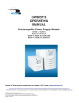
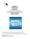
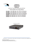
FALCON® ELECTRIC INC.
SVR SERIES
PRECISION UTILITY VOLTAGE
REGULATOR AND CONDITIONER
OWNER’S MANUAL
SVR1K-1T & SVR2K-2T
SVR2K-1T &SVR2K-2T
SVR3K-1 & SVR3K-2T
FALCON® Electric Inc., 5106 Azusa Canyon Rd., Irwindale, California 91706 800-842-6940 Fax: 626-962-7720 Email: [email protected]
2005 Falcon®Electric Inc. All rights reserved.
All other brand names and trademarks are the property of their respective owners.
The information and specifications stated in this document are subject to change without notice. 2005-03-21
® Falcon, Falcon Electric and UPS Plus logos are registered trademarks of Falcon Electric , Inc.
OM48021-1 Rev. C
1
SVR SERIES FEATURES
•
•
•
•
•
•
•
•
COMPACT SIZE, LIGHT WEIGHT
WIDE INPUT VOLTAGE WINDOW
TIGHT OUTPUT VOLTAGE REGULATION (±2%)
INPUT POWER FACTOR CORRECTION
SURGE PROTECTION
HIGH EFFICIENCY
OVER CREST RATIO LED INDICATOR
RS-232 INTERFACE
SYSTEM BLOCK DIAGRAM
OM48021-1 Rev. C
2
This following User’s Manual is provided to better enhance your understanding of the product and ensure its proper
installation and usage. Reading this manual carefully prior to installation of the SVR Series Precision Utility Voltage
Regulator and Conditioner will save time and ensure worry-free operation.
IMPORTANT SAFETY INSTRUCTIONS
SAVE THESE INSTRUCTIONS
This manual contains important safety instructions that must be followed during the installation, operation and
maintenance of this equipment. Please store this manual in a safe place for future reference.
STORAGE & INSTALLATION
CAUTION:
All of the SVR models presented herein are designed for installation and use in a controlled
enviroment free of dust, dirt and water.
The SVR Series Precision Utility Voltage Regulator and Conditioner is designed for installation in a controlled
environment (temperature controlled, indoor area free of conductive contaniments).
The system is lightweight and can be easily moved. Some important points to consider when positioning a unit for
operation:
∗ It is preferable that a dedicated outlet is accessible to connect the SVR. DO NOT modify the supplied cord in any way
nor should an extension cord of any kind be used.
∗ The cord paths in the system installation should remain clear of foot traffic or anything else that may disturb
permanent connection.
∗ The installation site should maintain an ambient air temperature of less than 104oF (40oC). When the environment for
the system remains cooler during operation, there is less stress on internal electronics. An air conditioned
environment will yield the longest SVR life.
∗ The SVR air inlets, vents and fan should not be obstructed or blocked in any way. The more breathing space the
system has, the cooler it operates.
∗ The air should remain free from excessive dust and chemical fumes.
Once a location has been selected and the unit is installed, it is ready for operation.
This Symbol Denotes Earth Ground
This Symbol Denotes On and Off
OM48021-1 Rev. C
3
CARE & MAINTENANCE
The SVR Series Precision Utility Voltage Regulator and Conditioner is designed to be maintenance-free. It can be
cleaned with a damp cloth or nonabrasive cleanser providing it is turned off and the input plug is disconnected from the
utility source. Be sure vents and fans are kept free from accumulation of dust, dirt or lint.
FALCON® ELECTRIC SVR SERIES
INSTALLATION AND STARTUP CHECK LIST
1.
Verify the following is included in the SVR shipping carton:
•
SVR
•
Power Cord
•
Owner’s Manual
2.
Verify that the SVR unit is configured for the proper input/output voltage and frequency. This information is stated
on the nameplate label located on the rear panel of the unit as well as setting dip switch settings also located on
the SVR rear panel.
3.
For the 1kVA model, connect the power cord to the inlet located on the SVR rear panel.
4.
Select a suitable location for the SVR near enough to the computer or equipment to connect the power cord.
Verify the location you have selected has adequate ventilation to allow for the proper cooling of the SVR. DO
NOT
BLOCK SVR FANS OR AIR VENTS. THE SVR MUST NOT BE INSTALLED IN AN ENCLOSED AREA.
5.
after
Turn the input switch located on the SVR rear panel to the “on” position. The internal SVR fan will turn on and
several seconds the front panel “line” indicator should turn on, followed by the “inverter” indicator.
6.
Turn on the connected equipment and verify the SVR does not go into overload, by using the front panel load
indicator.
IMPORTANT
TO TURN OFF THE SVR, TURN OFF THE INPUT CIRCUIT BREAKER. THE SVR WILL RUN FOR ABOUT 30
SECONDS AND SHUTDOWN.
OM48021-1 Rev. C
4
FRONT PANEL INDICATOR AND FUNCTION KEYS
5
1
6
4
8
7
2
3
LOAD LEVEL INDICATOR LEDS
1
•
•
•
2
The first or bottom LED is lit when the output load is greater than 25% of the rated output of the SVR.
The second LED is lit when the output load is greater than 50% of the rated output of the SVR.
The third LED is lit when the output load is greater than 75% of the rated output of the SVR.
BYPASS INDICATOR LED (Not on frequency converter models)
•
When this LED is lit, the SVR bypass is active. Should the Alarm LED be lit
at the same time, the SVR detected an internal failure and must be
serviced.
REGULATOR INDICATOR LED
3
•
4
When this LED is lit, the SVR inverter is operating and powering the
connected load.
OVER CREST INDICATOR LED
•
OM48021-1 Rev. C
This LED lights when the connected load is getting close to the peak current
rating of the SVR.
5
5
FAULT INDICATOR LED
This LED is lit during the following conditions:
• The inverter voltage is too high or low.
• SVR over temperature condition.
• Internal DC Bus has an under or over voltage condition.
• Internal microprocessor or memory failure.
ON / OFF BUTTON
6
The following describes the different modes of operation for this button:
• Pressing this button while the SVR is on and utility is present will turn the SVR inverter and output off.
• TO TURN SVR ON : CONNECT THE SVR TO UTILITY POWER AND TURN ON THE
MAIN CIRCUIT BREAKER. DO NOT PRESS THE ON BUTTON LOCATED ON THE FRONT PANEL.
• TO TURN SVR OFF: TURN OFF THE MAIN CIRCUIT BREAKER.
7
TEST BUTTON (Only present on SVR models with internal battery option installed)
The following describes the different modes of operation for this button:
• Pressing the Test button while utility is present will put the SVR through a self test
diagnostic.
8
LINE INDICATOR LED
•
OM48021-1 Rev. C
This LED is lit to a steady on state when Utility voltage is present.
6
Audiable Alarms
Audible alarm signals are divided into two catagories. Each category represents a different level of alarm status.
Catagory One Alarms represent normal or correctable operational alarms. Category Two Alarms are sounded in
the event of abnormal operation This will provide the end-user a more detailed notification of the SVR’s status.
1.
Category One Alarms:
• One long beep prior to a short beep, lets the user know the SVR is in an OVER LOAD, OVER CREST,
or FAULT situation.
── − = SVR IS IN OVERLOAD OR OVER CREST
• When ON/OFF button pressed, the associated actions will be initiated and there will be one short
beep.
− = WHEN SVR FRONT PANEL BUTTON DEPRESSED
• When the INITIAL SELF-TEST has been completed, there will be one short beep.
− = WHEN SVR FRONT PANEL BUTTON DEPRESSED
2.
Category Two Alarms:
• Three short beeps: indicates the SVR output voltage is out of proper operating range.
− − − = SVR OUTPUT VOLTAGE OUT OF PROPER RANGE.
• Four short beeps: indicates the SVR output frequency is out of proper operating range.
− − − − = SVR OUTPUT FREQUENCY OUT OF PROPER RANGE.
• Five short beeps: indicates the SVR is in an over-temperature condition.
− − − − − = SVR INTERNAL TEMPERATURE TOO HIGH
3.
If the INITIAL SELF-TEST cannot be completed after start-up, the SVR will sound the following alarms upon the
stated conditions:
•
Continuous rapid beeping for about 5 seconds and the SVR shuts down - Output voltage over range.
− − − − − − − − − − − − − − − − − − − − − − − − − = Output voltage over range.
•
Continuous rapid beeping for about 2 seconds and the SVR shuts down - The SVR performed a DC start, but
there is no output frequency set in memory.
− − − − − − − − − − = The SVR performed a DC start, but there is no output frequency set in memory.
OM48021-1 Rev. C
7
DIP SWITCH SETTINGS
(All SVR 1kVA – 3kVA Models)
OFF = 0
DIP
SWITCHES
SELECTION
TABLE
ON = 1
REAR PANEL VIEW
FOR 100-120Vac NOMINAL LINE VOLTAGE
SW2
SW1
VOLTAGE
Down
Down
100V
Down
Up
110V
Up
Down
120V
Up
Up
115V
FOR 220-240Vac NOMINAL LINE VOLTAGE
SW2
SW1
VOLTAGE
Down
Down
220V
Down
Up
230V
Up
Down
240V
Up
Up
200V
Up
SW3 – DISABLED
GREEN MODE OFF (Default)
NOTE: THE SVR MUST BE TURNED OFF AND BACK ON BEFORE NEW DIP SWITCH SETTINGS WILL BECOME
ACTIVE.
WARNING – REFER THE SERVICING OF THIS EQUIPMENT TO QUALIFIED SERVICE PERSONNEL ONLY.
WARNING – NEVER SERVICE THIS UNIT WHILE THE POWER IS APPLIED; HIGH VOLTAGE EXISTS AND A
HAZARD OF ELECTRICAL SHOCK IS PRESENT.
WARNING – THIS DEVICE IS INTENDED FOR ADMINISTRATION AND LAB USE. NOT INTENDED FOR LIFE
SUPPORT APPLICATIONS.
OM48021-1 Rev. C
8
INSTALLATION DETAILS
SVR1K-1, SVR2K-1, SVR3K-1, SVR1K-2T, SVR2K-2T & SVR3K-2T Tower Models
TYPICAL FRONT VIEW
Input Power
Circuit Breaker
(On the rear panel)
Front Control
panel
Cooling Vents
Must not be
obstructed
REAR VIEW
SVR1K-1T
DIP SWITCHES
COVER PLATE
FOR
OPTIONAL
SNMP AGENT
RS-232
CONNECTOR
COOLING FAN
DO NOT BLOCK
INPUT CIRCUIT BREAKER
OUTPUT
RECEPTACLES
(6 places without
external battery
option, 4 places as
shown)
POWER INLET
OM48021-1 Rev. C
OPTIONAL EXTERNAL
BATTERY CONNECTOR
9
REAR VIEW
SVR1K-2T
DIP SWITCHES
COVER PLATE
FOR OPTIONAL
SNMP AGENT
RS-232
CONNECTOR
COOLING FAN
DO NOT BLOCK
OUTPUT
RECEPTACLES
INPUT FUSE
4 each IEC 320
POWER INLET
OPTIONAL EXTERNAL
BATTERY CONNECTOR
REAR VIEW
SVR2K-1T & SVR3K-1T
DIP SWITCHES
COVER PLATE FOR
OPTIONAL SNMP
AGENT
RS-232
CONNECTOR
COOLING FANS
DO NO BLOCK
Optional
Receptacle
Configuration
Shown
OUTPUT FUSES
(2 places)
Contact Factory
For Other
Configurations
OPUTPUT
RECEPTACLES
(6) NEMA 5-15R
STANDARD
MAIN POWER SWITCH
& INPUT CIRCUIT
BREAKER
INPUT LINE
CORD
OM48021-1 Rev. C
OTHER OUTPUT RECEPTACLE
CONFIGURATIONS ARE
AVAILABLE.
10
REAR VIEW
SVR2K-2T & SVR3K-2T
DIP SWITCHES
COVER PLATE FOR
OPTIONAL SNMP
AGENT
RS-232
CONNECTOR
COOLING FANS
DO NOT BLOCK
OUTPUT FUSE S
(2 places)
OPUTPUT
RECEPTACLES
Shown with (1) L6-20R
& (2) 5-20R Receptacles
MAIN POWER SWITCH &
INPUT CIRCUIT BREAKER
LINE CORD INLET
OTHER OUTPUT RECEPTACLE
CONFIGURATIONS AVAILABLE
OM48021-1 Rev. C
11
GENERAL PROVISIONS
FALCON® ELECTRIC INC. hereby warrants product shipped under this agreement to be free from defective workmanship for a period of two years
following date of shipment. This Limited New Product Warranty Agreement only applies to covered repairs to the product occurring within the United
States and Canada.
EXCLUSIONS:
The following are not covered by the Falcon Electric Limited New Product Warranty.
1. DAMAGE DUE TO ACCIDENTS, FRAUD, INTENTIONAL NEGLIGENCE, MISUSE, IMPROPER INSTALLATION, UNAUTHORIZED
ADJUSTMENTS, MODIFICATION, ALTERATIONS, DISCONNECTION, TAMPERING: Accidents or acts of nature or other events beyond the
control of Falcon Electric, damage from impact, contaminants, fire, or water, misuse of the product such as sustained overloading, improper
installation or operation, operation in an un-controlled environment.
2. DAMAGE DUE TO IMPROPER INSTALLATION OR LACK OF MAINTENANCE: Lack of proper maintenance as outlined in the owner’s
manual.
3. NORMAL MAINTENANCE: Cleaning, replacement of leaking or outdated batteries.
4. DAMAGE DUE TO ALTERATIONS: Alterations by changing or adding to the product by any unauthorized personnel or service organization.
5. DAMAGE CAUSED BY OTHER THAN ORIGINAL EQUIPMENT PARTS. Any malfunctions caused by the use of other than Falcon Electric
original equipment parts such as batteries, line cords and plugs, output receptacles, or any other part.
6. BROKEN OR TAMPERED WARRANTY SEALS: Falcon Electric will deem all warranties null and void in the event warranty seals are broken
or show signs of removal or tampering.
7. CONSEQUENTIAL DAMAGES: This Limited New Product Warranty does not cover any consequential or secondary damages that may be
suffered as a result of usage of the product or the need to repair or replace a warranted part except to the extent coverage of such damage is
required by the state whose law governs the Falcon Electric Limited New Product Warranty.
8. REPAIRS BY UNAUTHORIZED SERVICE ORGANIZATIONS OR PERSONNEL: Otherwise covered repairs when the prescribed repair is not
performed by the Falcon Electric Service Center or by a Falcon Electric authorized third party service organization.
9. LIABILITY FROM USE OF THE PRODUCT: Liability for damage to property or injury or death of any person arising out of the operation,
maintenance, or use of the product weather.
10. This product is not recommended, and Falcon Electric inc. will not knowingly sell this product, for use with life support and other designated
"critical devices". ANY SUCH USE BY A USER AUTOMATICALLY VOIDS AND DISCLAIMS ANY AND ALL WARRANTIES, INCLUDING
ANY IMPLIED WARRANTY OF MERCHANTABILITY, IMPLIED WARRANTY OF FITNESS FOR A PARTICULAR PURPOSE, AND
EXPRESS WARRANTIES THAT THIS PRODUCT WILL CONFORM TO ANY AFFIRMATION OR PROMISE, FOR THIS PRODUCT AND
THE USER AGREES THAT IN NO EVENT SHALL FALCON ELECTRIC INC. BE LIABLE FOR CONSEQUENTIAL OR INDIRECT
DAMAGES.
LIMITS OF LIABILITY:
LIMITATION OF LIABILITY: THERE IS NO LIABILITY FOR INCIDENTAL OR CONSEQUENTIAL LOSS OR DAMAGE UNDER THESE
WARRANTIES INCLUDING BUT NOT LIMITED TO, LIABILITY FOR INJURY, LOSS OF LIFE, PROPERTY DAMAGE, LOSS OF USE, LOSS OF
DATA, LOSS OF TIME, INCONVENIENCE OR COMMERCIAL LOSS, OR BREACH OF IMPLIED OR EXPRESSED WARRANTIES. ANY AND
ALL SUCH LIABILITY IS EXPRESSLY EXCLUDED. IN NO EVENT SHALL FALCON ELECTRIC BE RESPONSIBLE FOR ANY AMOUNT
EXCEEDING THE ACTUAL MARKET VALUE OF THE PRODUCT. Some states do not permit the exclusions of limitations of incidental or
consequential damages, so these limitations may not apply to you.
1.
TRANSFER:
This Falcon Electric Limited New Product Warranty is not transferable in the event of the product ownership being transferred during the warranty
coverage period.
ITEM COVERAGE:
Effective January 1, 2000 FALCON® ELECTRIC hereby warrants product shipped under this Agreement to be free from defective
workmanship for a period of two years following date of shipment. Coverage under this Falcon Electric New Product Warranty
Agreement commences with the date of shipment defined as the date on the Bill of Lading. If no Bill of Lading is issued, the date
of shipment shall be shown on seller's shipping document. The Falcon Electric Limited New Product Warranties expire two years
from the aforementioned commencement date. Falcon Electric, Inc. reserves the right to make changes, additions, and/or other
improvements in its products without incurring any obligation to install them on its products previously sold. This Warranty is valid
for product as sold.
For product located in the continental United States and Canada deemed by Falcon Electric to be covered under this warranty, Falcon
Electric will pay shipping costs associated with the return and repair of product under the following conditions only:
a. Falcon Electric will pay shipping costs both to and from our U.S. Service Center for the first 30 days from the original date of
invoice. During this 30 day period Falcon Electric may elect to ship a new unit to replace the defective product.
b. After the first 30 days and up to 90 days from the original date of invoice the end-user is responsible for shipping costs
associated with sending the defective unit to the Falcon Electric U.S. Service Center. Falcon Electric will pay shipping costs
associated with returning the repaired product to the end-user. During this 60 day period Falcon Electric may elect to offer a
loaner unit, providing the end-user agrees to pay for all shipping costs associated with transportation of the loaner unit both
from and return to the Falcon Electric U.S. Service Center.
c.
All shipping costs for product submitted beyond 90 days of the original date of invoice is the responsibility of the enduser.
OM48021-1 Rev. C
12
FCC CONSIDERATIONS
This equipment generates and uses radio frequency energy and if not installed and used properly in strict
accordance
with the manufacturer’s instructions, may cause interference to radio and television reception. All models covered in
this manual have been tested and found to comply with the limits for a Class A computing device, in accordance with
the specifications in FCC regulations, Part 15, Subpart J, which are designed to provide reasonable protection
against
Such interference.
TECHNICAL SUPPORT AND SERVICE
Your SVR is backed be one of the finest customer service teams assembled. Write, call, fax or email should you
require technical assistance or service.
Falcon Electric Inc,
5106 Azusa Canyon Road
Irwindale CA, 91706
(800) 842-6940; (626) 962-7770
Fax: (626) 962-7720
[email protected]
Should service be desired, you must first obtain a Return Material Authorization number (RMA) and shipping
instructions from our customer service department. Please have your SVR Series model and serial number(s)
on hand prior to the call. This information is located on the identification label on the rear panel of the unit. This
information is essential in retrieving your unit’s history records.
The RMA number issued must appear on the outside of the shipping carton. The original shipping container
must be used when returning any SVR Series product. Falcon Electric will not assume any responsibility for
shipping damage. In the event of shipping damage, you will be charged for repairs due to the damage.
All units must be returned prepaid. The address and shipping instructions will be given to you at the time the
RMA is issued.
OM48021-1 Rev. C
13