1
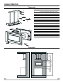
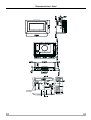
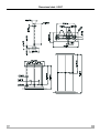
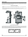
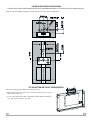
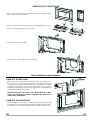
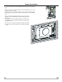
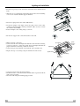
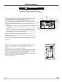
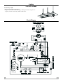
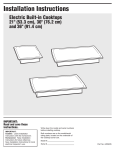
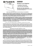
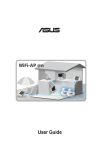
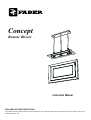
Concept
Remote Blower
Instruction Manual
READ AND SAVE THESE INSTRUCTIONS
The Installer must leave these instructions with the homeowner. The homeowner must keep these instructions for future reference and for local
electrical inspectors’ use.
CONTENTS
2
WARNING
3
CHARACTERISTICS
5
INSTALLATION
8
USE
13
MAINTENANCE
14
EN
READ THESE INSTRUCTIONS BEFORE YOU START INSTALLING THIS RANGEHOOD
READ AND SAVE THESE INSTRUCTIONS
WARNING: - TO REDUCE THE RISK OF A RANGE TOP GREASE FIRE: Never leave surface units unattended at high settings. Boilovers
cause smoking and greasy spillovers that may ignite. Heat oils slowly on low or medium setting. Always turn hood ON when cooking at high
heat or when flambeing food (i.e. Crepes Suzette, Cherries Jubilee, Peppercorn Beef Flambè). Clean ventilating fans frequently. Grease
should not be allowed to accumulate on fan or filter. Use proper pan size. Always use cookware appropriate for the size of the surface element.
WARNING: - TO REDUCE THE RISK OF INJURY TO PERSONS IN THE EVENT OF A RANGE TOP GREASE FIRE, OBSERVE THE
FOLLOWING: SMOTHER FLAMES with a close-fitting lid, cookie sheet, or metal tray, then turn off the burner. BE CAREFUL TO PREVENT
BURNS. If the flames do not go out immediately EVACUATE AND CALL THE FIRE DEPARTMENT. NEVER PICK UP A FLAMING PAN - You
may be burned. DO NOT USE WATER, including wet dishcloths or towels - a violent steam explosion will result. Use an extinguisher ONLY if:
1. You know you have a Class ABC extinguisher, and you already know how to operate it. 2. The fire is small and contained in the area where
it started. 3. The fire department is being called. 4. You can fight the fire with your back to an exit.
CAUTION: To Reduce The Risk Of Fire And Electric Shock, Install This RangeHood Only With Remote Blower Models Rated Maximum. 4,2 A
suitable for use with solid stade speed controls.
WARRANTY & SERVICE
This rangehood carries a limited warranty against manufacturer’s defects. To obtain warranty service, contact the dealer from whom you
purchased the rangehood, or the local Faber distributor. If you cannot identify a local Faber distributor, contact Faber USA at (508) 358-5353 for
the name of a distributor in your area.
USE AND CARE INFORMATION
This rangehood system is designed to remove smoke, cooking vapors and odors from the cooktop area. This unit also has several features
to insure operator safety.
VENTING REQUIREMENTS
Determine which venting method is best for your application. Ductwork can extend either through the wall or the roof.
The length of the ductwork and the number of elbows should be kept to a minimum to provide efficient performance. The size of the ductwork
should be uniform. Do not install two elbows together. Use duct tape to seal all joints in the ductwork system. Use caulking to seal exterior wall
or floor opening around the cap. Flexible ductwork is not recommended. If it is used, each foot of flexible ductwork used is equivalent to two feet
of straight metal ductwork when calculating the ductrun length. Thus, a flexible elbow equals two standard elbows.
Make sure there is proper clearance within the wall or floor for exhaust duct before making cutouts. Do not cut a joist or stud unless absolutely
necessary. If a joist or stud must be cut, then a supporting frame must be constructed. For best results, remote blowers should transition to 10"
round duct as soon as possible. If small ducting is used, it should be transitioned to 9 or 10" round as soon as possible.
WARNING - To Reduce The Risk Of Fire, Use Only Metal Ductwork.
!
WARNING
• Venting system MUST terminate outside the home.
• DO NOT terminate the ductwork in an attic or other enclosed space.
• DO NOT use 4" laundry-type wall caps.
• Flexible-type ductwork is not recommended.
• DO NOT obstruct the flow of combustion and ventilation air.
• Failure to follow venting requirements may result in a fire.
ELECTRICAL REQUIREMENTS
A 120 volt, 60 Hz AC-only electrical supply is required on a separate 15 amp circuit, fused on both sides of the line. A time-delay fuse or circuit
breaker is recommended. The fuse must be sized per local codes in accordance with the electrical rating of this unit as specified on the serial/
rating plate located inside the unit near the field wiring compartment. THIS UNIT MUST BE CONNECTED WITH COPPER
WIRE ONLY. Wire sizes must conform to the requirements of the National Electrical Code, ANSI/NFPA 70 - latest edition, and all local codes and
ordinances. Wire size and connections must conform with the rating of the appliance. Copies of the standard listed above may be obtained
from:
National Fire Protection Association
Batterymarch Park
Quincy, Massachusetts 02269
EN
3
This appliance should be connected directly to the fused disconnect (or circuit breaker) through flexible, armored or nonmetallic sheathed
copper cable. Allow some slack in the cable so the appliance can be moved if servicing is ever necessary. A UL Listed, 1/2" conduit connector
must be provided at each end of the power supply cable (at the appliance and at the junction box).
When making the electrical connection, cut a 1 1/4" hole in the wall. A hole cut through wood must be sanded until smooth. A hole through metal
must have a grommet.
SUITABLE FOR USE WITH SOLID STATE SPEED CONTROLS. WARNING - TO REDUCE THE RISK OF FIRE, ELECTRICAL SHOCK, OR
INJURY TO PERSONS, OBSERVE THE FOLLOWING: Use this unit only in the manner intended by the manufacturer. If you have any questions,
contact the manufacturer.
Before servicing or cleaning unit, switch power off at service panel and lock the service disconnecting means to prevent power from being
switched on accidentally. When the service disconnecting means cannot be locked, securely fasten a prominent warning device, such as a tag,
to the service panel.
CAUTION: For General Ventilating Use Only. Do Not Use To Exhaust Hazardous or Explosive Materials and Vapors.
WARNING - TO REDUCE THE RISK OF FIRE, ELECTRICAL SHOCK, OR INJURY TO PERSONS, OBSERVE THE FOLLOWING: Installation
Work And Electrical Wiring Must Be Done By Qualified Person(s) In Accordance With All Applicable Codes And Standards, Including Fire-Rated
Construction.
Sufficient air is needed for proper combustion and exhausting of gases through the flue (chimney) of fuel burning equipment to prevent
backdrafting. Follow the heating equipment manufacturer’s guideline and safety standards such as those published by the National Fire
Protection Association (NFPA), and the American Society for Heating, Refrigeration and Air Conditioning Engineers (ASHRAE), and the local
code authorities.
When cutting or drilling into wall or ceiling, do not damage electrical wiring and other hidden utilities.
Ducted fans must always be vented to the outdoors.
!
WARNING
• Electrical ground is required on this rangehood.
• If cold water pipe is interrupted by plastic, nonmetallic gaskets or other materials, DO NOT use for grounding.
• DO NOT ground to a gas pipe.
• DO NOT have a fuse in the neutral or grounding circuit. A fuse in the neutral or grounding circuit could
result in electrical shock.
• Check with a qualified electrician if you are in doubt as to whether the rangehood is properly grounded.
• Failure to follow electrical requirements may result in a fire.
4
EN
CHARACTERISTICS
Components
12
D
1
Q.ty
1
Hood Body, complete with: Blower, Filters, Controls
C
2
1
Built-in hood body case
3
1
Rear remote motor connection panel
4
1
Top air outlet flange with valve
5
1
Top air outlet plug
10
1
Light
11
4
Support arms
12
2
Bush masking plug
13
2
Arm support bush
A
10
Screws 3,5 x 16
C
4
Screws 5 x 70
D
4
Wall Plugs ø 10
E
2
Screwsfor wall plugs ø 5
F
2
Wall Plugs ø 5
G
4
Grub screws
F
E
13
G
11
10
5
2
4
3
1
A
98-7/16 - 118-1/8
5-29/32
5-29/32
22-3/4
28-7/16 - 48-1/8
Dimensions
EN
5
Dimensional chart - Hood
Distance from
the Hob
6
EN
Dimensional chart - LIGHT
EN
7
INSTALLATION
The hood can be installed in the following ways: top air outlet, bottom air outlet, rear air outlet. Once the desired configuration has been chosen
(see the diagrams below) it will be necessary to provide an opening in the wall where to house the built-in hood body case. Besides the air
ducting pipes, basing on the chosen configuration, the hood has to be electrically connected, and an additional connection raceway between
the hood installation area and the lighting area has to be provided.
HOOD INSTALLATION SCHEME
RECESSED HOUSING LOWER BORDER SHALL BE INSTALLED AT THE MINIMUM DISTANCE OF 7-3/32 IN. ABOVE THE COOKING
SURFACE.
• Basing on the following scheme prepare the opening H for housing the built-in hood body case. In case of the bottom air outlet
configuration consider that the holes for electrical connection have to be made up on the left side (position U).
• Concerning the ductrun consider the figures in the following scheme bearing in mind that the rear hole P serves only for the rear
air outlet-configuration.
3-11/32
10
7/8
U
P
H
CALCULATE THE DUCTRUN LENGTH
The ductwork length should not exceed 35 equivalent feet for 3 1/4" X 10" duct, or 55 equivalent feet for 9" or 10" round duct. Calculate the
length of the ductwork by adding the equivalent feet listed in FIGURE 1 for each piece of duct in the complete system. An example is given in
FIGURE 2. For best results, use no more than three 90° elbows. Make sure that there is a minimum of 24" of straight duct between elbows if
more than one is used. Do not install two elbows together. Round duct is recommended instead of rectangular duct especially if elbows are
needed. For internal blower models, rectangular duct should be transitioned to 9" round as soon as possible.
45° Elbow
90° Elbow
90° Flat Elbow
Wall Cap
5.0 feet
7.0 feet
12.0 feet
0.0 feet
FIGURE 1
8
9 Feet Straight Duct 9.0 feet
2 - 90° Elbows
14.0 feet
Wall Cap
0.0 feet
Total System
23.0 feet
FIGURE 2
EN
LIGHTING UNIT INSTALLATION SCHEME
LIGHTING UNIT LOWER BORDER SHALL BE INSTALLED AT THE MINIMUM DISTANCE OF 34 9/16 IN. ABOVE THE COOKING SURFACE.
With the aid of the drilling template provided mark the necessary holes and drill them.
6
5/1
ø1
TOP OR BOTTOM AIR OUTLET CONFIGURATION
The hood is manufactured with the air outlet at the top.
• Fit the flange with non-return valve onto the air outlet position of the
built-in hood body case.
• In case of the bottom air outlet configuration turn the built-in hood body
case 180° before fixing it to the wall.
EN
9
REAR AIR OUTLET CONFIGURATION
• Remove the suction panel by unfastening the 8 screws around the frame.
• Remove the metal grease filters.
• Remove the metal profile fixed to the flange by unfastening the 5 screws.
• Fit the air outlet plug into the top air outlet.
• Remove the rear air outlet plug .
• Fit the rear air outlet flange in place of the plug
Built-in hood body case installation
FIXING INTO THE BRICK WALL
• With the aid of pliers bend the lateral metal tongues of the built-in case.
• It is necessary to wall the built-in hood body case inside the hollow in
the wall paying attention that the external edge of the built-in case adheres
perfectly to the wall. It is necessary that the built-in case is precisely
levelled both horizontally and vertically, and that the air outlet flange is
correctly placed inside the ductrun.
BEFORE INSTALLING THE HOOD IT WILL BE NECESSARY TO WAIT
UNTILL THE BUILT-IN HOOD BODY CASE WALLING PROCESS IS
COMPLETELY TERMINATED.
FIXING INTO THE WOODEN WALL
• Insert the built-in hood body case inside the wall paying attention that
the built-in case is precisely levelled both horizontally and vertically.
• Fix the built-in case to the wall using the 10 screws A (3,5x16) provided.
10
EN
Hood body installation
• In case of the bottom air outlet configuration the hood body has to be turned
180°.
• Remove the top cover of the terminal box by unfastening the two screws
fixing it to the hood casing.
• With the aid of pliers brake through a hole inside the terminal box
providing thus for a passage of the electrical connection for the lighting
unit.
• Place the hood body inside the built-in case paying attention
that the screws of the built-in case fall to the gaps of the
hood body.
• Once the screws have reached the gaps it is necessary to
fasten them in order to definitively fix the hood body inside
the built-in case.
• It is necessary to make sure that the hood body air outlet is
correctly in its’ position inside the air outlet of the builtin case.
EN
11
Lighting unit installation
• Provide for passage of the electrical connection wires with the hood
body.
• Slide the top cover downwards, unfastening the two side screws and taking
care not to scratch the tubular support members.
• Insert the 4 plugs D into the earlier drilled holes.
• Decide the height of the light; loosen the grub screws on the outer
columns to allow the light to slide up and down. Take care not to scratch
the columns when sliding.
• Fasten the light to the ceiling using 4 screws C.
• Fix the two support arm connection bushes to the wall..
• Make electrical connection:
• Connect the red wire in the Light-unit with the red lead in the hood using
a twist-on connector; connect the purple wire in the Light-unit with the
purple lead in the hood using a twist-on connector.
• Connect the green ground wire to the unused, green ground screw.
• Replace the top cover, fixing it in place with the two side screws.
green
ground
screw
hood wiring
light wiring
purple wiring
red wiring
twist-on
connectors
• Screw the support arms into their housings.
• Hook them to the connection bushes and lock them in position with the
grub screws provided.
• Close the bush using the masking plug provided
12
EN
Electrical connection
!
WARNING
ELECTRICAL SHOCK HAZARD
• Disconnect power before making electrical connctions.
• Connect ground wire to green ground screw in terminal box.
green
ground
• Connect the red wire of the Light cable with the red lead in the hood
screw
hood
wiring
hood wiring
using a twist-on connector; connect the purple wire of the Light cable
with the purple lead in the hood using a twist-on connector.
• Connect the blue blower wire with the blue lead in the hood using a twiston connector; connect the brown blower wire with the brown lead in the
black wiring
hood using a twist-on connector.
• Connect the ligth unit to the ground using one of the following two alternative ways:
a- Connect the domestic green ground wire under the unused green ground white wiring
screw belonging to the light unit wiring box using a listed conduit
power
connector.
supply
b- Connect one end of the green ground wire (max lenght 10 yards using
light wiring
conduit
14 awg wire) under the unused green ground screw belonging to the
purple wiring red wiring
light unit wiring box and the other end under the unused green ground
screw belonging to the range hood wiring box.
• Connect the green ground wire (from exterior blower and from power
supply cable) under the unused green ground screw.
• Tighten strain relief screws.
• Connect the white wire of the power supply conduit with the white lead
in the hood using a twist-on connector; connect the black wire of the
power supply conduit with the black lead in the hood using a twist-on
connector.
twist-on
connectors
blue wiring
brown wiring
exterior
blower
wiring
• Place the suction panel so that the connection flat wiring for the hood
controls passes through the specific opening in the hood body.
• Fix the suction panel to the hood body fastening the screws removed
earlier.
• Open the suction cover using the lever provided.
• Connect the flat connection wiring coming from the hood controls with
the connector piece placed close to the terminal box. Only in case of the
bottom air outlet configuration remove the protection cover from the
connector piece on the opposite side of the terminal box.
• Fix the terminal box cover again and fasten the 2 screws removed earlier.
• Replace the metal grease filters in their housings.
• Close the suction panel.
EN
13
USE
Control Panel
S1
L
T1
T2
T3
T4
The hood can be switched on pushing directly onto the requested speed without firstly having to select 0/1 button.
LED
FUNCTIONS
L
0/1 Light
Turns lighting on and off.
T1
0/1 Motor
Fixed
T2
T3
Speed
Speed
Fixed
on
T4
Speed
Fixed
Flashing
S1
Led
Fixed
Flashing
First speed.
When pressed for about 2 seconds the motor is switched off.
Second speed.
Third speed.
Max. speed
Intensive speed.
Suitable for the strongest cooking vapours and odours. The function becomes active when the
button is pushed for about 2 seconds. After 10 minutes of functioning it turns off automatically.
This function can be interrupted by means of pressing any of the buttons.
Indicates that the Metal grease filters saturation alarm has been triggered, and the filters need to
be washed. The alarm is triggered after 100 working hours. (Reset; check the Maintenanceparagraph)
indicates that the activated charcoal odour filter saturation alarm has been triggered, and the
filter has to be replaced; the metal grease filters must also be washed. The activated charcoal
odour filter is triggered after 200 working hours. (Activation and Reset; check the Maintenanceparagraph)
MAINTENANCE
Grease filters
CLEANING METAL GREASE FILTERS
•Alarm signal reset
• Switch off the lights and extractor motor.
• Press button T3 for at least 3 seconds, until the leds start to flash.
Cleaning the filters
• Open the suction cover using the lever provided.
• The filters are washable and must be cleaned when the Led S1 lights up
or at least every 2 months of operation, or more frequently for particularly
heavy usage.
• Remove the filters one at a time by pushing them towards the back of the
group and pulling down at the same time.
• Wash the filters, taking care not to bend them. Allow them to dry before
refitting.
• When refitting the filters, make sure that the handle is visible on the
outside.
• Close the suction panel.
14
EN
Lighting
LIGHT REPLACEMENT
20 W halogen light.
• Extract the lamp from the Support.
• Replace with another of the same type, making sure that the two pins are
properly inserted in the lamp holder socket holes.
Electric Diagram
EN
15
436002499_02 - 041103