1
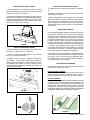
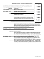
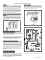
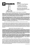
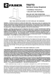
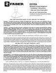
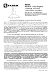
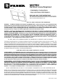
MATRIX
Wall Mount Luxury Rangehood
• Installation Instructions
• Use and Care Information
READ AND SAVE THESE INSTRUCTIONS
The Installer must leave these instructions with the homeowner.
The homeowner must keep these instructions for future reference
and for local electrical inspectors' use.
READ THESE INSTRUCTIONS BEFORE YOU START INSTALLING THIS RANGEHOOD
WARNING: - TO REDUCE THE RISK OF A RANGE TOP GREASE FIRE: a) Never leave surface units unattended at high
settings. Boilovers cause smoking and greasy spillovers that may ignite. Heat oils slowly on low or medium setting. b)
Always turn hood ON when cooking at high heat or when flambeing food (i.e. Crepes Suzette, Cherries Jubilee, Peppercorn Beef Flambé). c) Clean ventilating fans frequently. Grease should not be allowed to accumulate on fan or filter. d)
Use proper pan size. Always use cookware appropriate for the size of the surface element.
WARNING: - TO REDUCE THE RISK OF INJURY TO PERSONS IN THE EVENT OF A RANGE TOP GREASE FIRE, OBSERVE
THE FOLLOWING: SMOTHER FLAMES with a close-fitting lid, cookie sheet, or metal tray, then turn off the burner. BE
CAREFUL TO PREVENT BURNS. If the flames do not go out immediately EVACUATE AND CALL THE FIRE DEPARTMENT.
NEVER PICK UP A FLAMING PAN - You may be burned. DO NOT USE WATER, including wet dishcloths or towels - a
violent steam explosion will result. Use an extinguisher ONLY if: 1. You know you have a Class ABC extinguisher, and
you already know how to operate it. 2. The fire is small and contained in the area where it started. 3. The fire department
is being called. 4. You can fight the fire with your back to an exit.
ALL WALL AND FLOOR OPENINGS WHERE THE RANGEHOOD IS INSTALLED MUST BE SEALED.
This rangehood requires at least 15" of clearance between the bottom of the rangehood and the cooking surface or countertop. This
hood has been approved by UL at this distance from the cooktop. The maximum depth of overhead cabinets is 13". Overhead
cabinets on both sides of this unit must be a minimum of 18" above the cooking surface or countertop. Consult the cooktop or range
installation instructions given by the manufacturer before making any cutouts. MOBILE HOME INSTALLATION The installation
of this rangehood must conform to the Manufactured Home Construction and Safety Standards, Title 24 CFR, Part 3280 (formerly
Federal Standard for Mobile Home Construction and Safety, Title 24, HUD, Part 280). Four wire power supply must be used and
the appliance wiring must be revised. See Electrical Requirements.
LISEZ BIEN CETTE FICHE AVANT D'INSTALLER LA HOTTE
AVERTISSEMENT - POUR MINIMISER LE RISQUE DʼUN FEU DE GRAISSE SUR LA TABLE DE CUISSON : a) Ne jamais laisser
un élément de la table de cuisson fonctionner sans surveillance à la puissance de chauffage maximale; un renversement/
débordement de matière graisseuse pourrait provoquer une inflammation et le génération de fumée. Utiliser toujours une
puissance de chauffage moyenne ou basse pour le chauffage dʼhuile. b) Veiller à toujours faire fonctionner le ventilateur
de la hotte lors dʼune cuisson avec une puissance de chauffage élevée ou lors de la cuisson dʼun mets à flamber (i.e.
Crepes Suzette, Cherries Jubilee, Peppercorn Beef Flambé). c) Nettoyer fréquemment les ventilateurs dʼextraction. Veiller
à ne pas laisser de la graisse sʼaccumuler sur les surfaces du ventilateur ou des filtres. d) Utiliser toujours un ustensile
de taille appropriée. Utiliser toujours un ustensile de taille adapté à la taille de lʼélément chauffant.
AVERTISSEMENT: - POUR PRÉVENIR LES BLESSURES EN CAS DE FEU SUIVRE LES RECOMMANDATIONS SUIVANTES:
ÉTOUFFEZ LE FEU avec un couvercle métallique et fermez le brûleur. Si le feu ne s'éteint pas tout de suite, QUITTEZ
LES LIEUX ET APPELEZ LES POMPIERS. NE TOUCHEZ JAMAIS UNE CASSEROLE EN FLAMMES. N'UTILISEZ JAMAIS
DE L'EAU ou un torchon mouillé pour éteindre le feu - ce qui pourrait causer une explosion de vapeur. N'utilisez un
extincteur que si: 1. Vous avez un modèle ABC et vous connaissez bien son mode d'emploi. 2. Le feu est petit et peu
répandu. 3. Les pompiers sont déjà prévenus. 4. Vous avez une sortie derrière vous.
TOUTE OUVERTURE DANS LE MUR OU LE PLANCHER À PROXIMITÉ DE LA HOTTE DOIT ÊTRE SCELLÉ
Gardez 15 po. de hauteur entre le bas de la hotte et la surface de cuisson Les armoires au-dessus de chaque côté devront être
au moins à 18 po. au-dessus de la surface de cuisson. Consultez la fiche technique avant de découper les armoires. L'installation
de cette hotte doit être conforme aux Réglements de Manufactured Home Construction and Safety Standards, titre 24 CFR,
Section 3280 (anciennement Federal Standard for Mobile Home Construction and Safety Standards, titre 24 CFR, Section 3280
(anciennement Federal Standard for Mobile Home Construction and Safety, titre 24, HUD, Section 280). Le branchement électrique
se fait avec une raccordement à 4 fils. Consultez la fiche technique électrique.
Version 09/05 - Page 1
VENTING REQUIREMENTS
Determine which venting method is best for your application.
Ductwork can extend either through the wall or the roof.
The length of the ductwork and the number of elbows should
be kept to a minimum to provide efficient performance. The
size of the ductwork should be uniform. Do not install two
elbows together. Use duct tape to seal all joints in the ductwork
system. Use caulking to seal exterior wall or floor opening
around the cap.
This appliance should be connected directly to the fused
disconnect (or circuit breaker) through flexible, armored or
nonmetallic sheathed copper cable. Allow some slack in the
cable so the appliance can be moved if servicing is ever necessary. A UL Listed, 1/2" conduit connector must be provided
at each end of the power supply cable (at the appliance and
at the junction box).
When making the electrical connection, cut a 1 1/4" hole in the
wall. A hole cut through wood must be sanded until smooth.
A hole through metal must have a grommet.
Flexible ductwork is not recommended. Flexible ductwork
creates back pressure and air turbulence that greatly
reduces performance.
WARNING - TO REDUCE THE RISK OF FIRE OR ELECTRIC
SHOCK, do not use this fan with any solid-state speed
control device.
Make sure there is proper clearance within the wall or floor
for exhaust duct before making cutouts. Do not cut a joist or
stud unless absolutely necessary. If a joist or stud must be
cut, then a supporting frame must be constructed
WARNING - TO REDUCE THE RISK OF FIRE, ELECTRICAL SHOCK, OR INJURY TO PERSONS, OBSERVE THE
FOLLOWING: Use this unit only in the manner intended
by the manufacturer. If you have any questions, contact
the manufacturer.
FOR MORE SPECIFIC DUCTWORK INFORMATION, GO
TO PAGE 4.
Before servicing or cleaning unit, switch power off at
service panel and lock the service disconnecting means
to prevent power from being switched on accidentally.
When the service disconnecting means cannot be locked,
securely fasten a prominent warning device, such as a
tag, to the service panel.
WARNING - To Reduce The Risk Of Fire, Use Only Metal
Ductwork.
! WARNING
• Venting system MUST terminate outside the
home.
• DO NOT terminate the ductwork in an attic or
other enclosed space.
• DO NOT use 4" laundry-type wall caps.
• Flexible-type ductwork is not recommended.
• DO NOT obstruct the flow of combustion and
ventilation air.
• Failure to follow venting requirements may result
in a fire.
ELECTRICAL REQUIREMENTS
A 120 volt, 60 Hz AC-only electrical supply is required on a
separate 15 amp fused circuit. A time-delay fuse or circuit
breaker is recommended. The fuse must be sized per local
codes in accordance with the electrical rating of this unit as
specified on the serial/rating plate located inside the unit
near the field wiring compartment. THIS UNIT MUST BE
CONNECTED WITH COPPER WIRE ONLY. Wire sizes
must conform to the requirements of the National Electrical
Code, ANSI/NFPA 70 - latest edition, and all local codes and
ordinances. Wire size and connections must conform with the
rating of the appliance. Copies of the standard listed above
may be obtained from:
National Fire Protection Association
Batterymarch Park
Quincy, Massachusetts 02269
For residential use only.
CAUTION: For General Ventilating Use Only. Do Not
Use To Exhaust Hazardous or Explosive Materials and
Vapors.
WARNING - TO REDUCE THE RISK OF FIRE, ELECTRICAL SHOCK, OR INJURY TO PERSONS, OBSERVE THE
FOLLOWING: Installation Work And Electrical Wiring Must
Be Done By Qualified Person(s) In Accordance With All
Applicable Codes And Standards, Including Fire-Rated
Construction.
Sufficient air is needed for proper combustion and
exhausting of gases through the flue (chimney) of fuel
burning equipment to prevent backdrafting. Follow the
heating equipment manufacturer's guideline and safety
standards such as those published by the National Fire
Protection Association (NFPA), and the American Society
for Heating, Refrigeration and Air Conditioning Engineers
(ASHRAE), and the local code authorities.
When cutting or drilling into wall or ceiling, do not damage electrical wiring and other hidden utilities.
Ducted fans must always be vented to the outdoors.
!
WARNING
• Electrical ground is required on this rangehood.
• If cold water pipe is interrupted by plastic,
nonmetallic gaskets or other materials, DO NOT
use for grounding.
• DO NOT ground to a gas pipe.
• DO NOT have a fuse in the neutral or grounding
circuit. A fuse in the neutral or grounding circuit
could result in electrical shock.
• Check with a qualified electrician if you are in doubt
as to whether the rangehood is properly grounded.
• Failure to follow electrical requirements may result
in a fire.
Version 09/05 - Page 2
Confirmer la sortie d'évacuation - soit par le mur, soit par
le toit.
AVERTISSEMENT - POUR RÉDUIRE LE RISQUE
D'INCENDIE OU DE CHOC ELECTRIQUE, ne pas utiliser
ce ventilateur en conjonction avec un dispositif de réglage
de vitesse à semi-conducteurs.
Utilisez une longueur de tuyauterie minimale avec les moindres
de coudes pour la plus grande efficacité. Le diamètre de
tuyauterie doit être uniforme. N'installez jamais 2 coudes
ensemble. Scellez bien tous les joints avec un ruban adhésif
métallique à l'intérieur et scellez bien le clapet extérieur avec
du calfeutrage.
AVERTISSEMENT – POUR MINIMISER LES RISQUES
DʼINCENDIE, CHOC ÉLECTRIQUE OU DOMMAGES
CORPORELS, OBSERVER LES PRESCRIPTIONS
SUIVANTES: Suivez les recommandations du fabricant
et entre en communication avec lui pour toute
information.
Utilisez un tuyau d'évacuation rigide lorsque possible.
Un tuyau flexible égale deux fois plus qu'un tuyau rigide,
ce qui réduit la puissance d'évacuation.
Fermez le courant avant tout entretien et veillez a ce qu'il
reste fermé. Si on ne peut pas verrouiller le panneaux
du service électrique, affichez un avis de danger sur la
porte.
RÈGLEMENTS D'ÉVACUATION
Veillez à ce que l'espace pour le tuyau soit ample - ainsi on
n'aurait pas besoin de découper les supports de mur intérieur.
Si ce découpage est nécessaire, veillez bien à ce qu'un
renforcement soit mis en place.
RÈGLEMENTS D'ÉVACUATION ADDITIONELL PAGE 4
AVERTISSEMENT - Pour Ne Pas Risquer Un Feu, Utilisez
Seulement Les Matériaux Métalliques.
! AVERTISSEMENT
• Le système d'évacuation DOIT sortir à l'extérieur.
• N'ÉVACUEZ PAS le conduit soit dans une
mansarde soit dans un espace enfermé.
• N'UTILISEZ PAS un clapet de séchoir à 4 pouces.
• N'utilisez pas un conduit flexible.
• N'ENCOMBREZ PAS la circulation d'air.
• Faute de suivre cet avertissement pourrait
occasionner un feu.
AVIS: Pour L'évacuation Générale - Veillez à Ne Pas
Evacuer Des Matériaux Ou Vapeurs Explosif.
AVERTISSEMENT – POUR MINIMISER LES RISQUES
DʼINCENDIE, CHOC ÉLECTRIQUE OU DOMMAGES
CORPORELS, OBSERVER LES PRESCRIPTIONS
SUIVANTES: L'installation Et Le Raccordement Electrique
Doivent Se Faire Par Un Technicien Qualifié Selon Tous
Les Codes Municipaux.
Afin d'obtenir un rendement maximal en ce qui a trait à la
combustion ainsi qu'à l'évacuation des gaz par la conduite
de cheminée, une bonne aération est nécessaire pour
tous les appareils à combustion. Suivez les conseils et
mesures de sécurité du fournisseur tels que ceux publiés
par l'Association Nationale de la Sauvegarde contre
l'Incendie et l'Association Américaine d'Ingénieurs de
Chauffage, Frigorifaction et Air Climatisé ainsi que les
codes municipaux.
En perçant un mur veillez à ne pas perforer un autre fil
électrique.
Une ventilateur à évacuation extérieure doit être
raccordée à l'extérieur.
FICHE TECHNIQUE ÉLECTRIQUE
Le raccordement électrique doit se faire avec un circuit séparé
de 15 ampères fusible à 120V, 60 Hz, courant alternant. On
recommande un coupe-circuit. La taille du fusible doit se
conformer aux codes municipaux suivant la spécification
électrique sur la plaque intérieure. Le diamètre du fil
devra aussi se conformer aux règlements du code national
électrique, ANSI/NFPA 70 - ainsi qu'aux règlements locaux
et les spécifications de cet appareil. On peut obtenir ces
informations chez:
l'Association Nationale de la Prévention du Feu
Batterymarch Park
Quincy, Massachusetts 02269
Raccordez cet appareil directement au coupe-circuit avec un fil
flexiblle couvert en cuivre en laissant un peu de lâchement dans
le fil pour permettre le déplacement de l'appareil. Veillez a ce
qu'un contact d'un demi-pouce (1/2 po.) soit installé à chaque
bout de fil (soit à l'appareil ainsi qu'à la boite à fusible).
Faites un trou de 1 1/4 po. dans le mur. S'il s'agit d'un trou en
bois - sablez-le bien, tandis qu'un trou passant par le métal
demande un bouche-trou.
! AVERTISSEMENT
• Une prise à terre est nécessaire pout cette hotte.
• N'utilisez pas un tuyau à l'eau froide pour la mise
à terre s'il est branché à un joint plastique, nonmétallique ou autre.
• NE JOIGNEZ PAS la mise à terre à conduit de gaz.
• N'INSTALLEZ PAS un fusible dans le circuit de
mise à terre - ce qui peut causer une secousse
électrique.
• Vérifiez avec un électricien certifié à ce que la hotte
soit bien mise à terre.
• Faute de suivre ces recommandations pourrait
occasionner un feu.
Uniquement pour usage menager.
Version 09/05 - Page 3
ING
PLAN THE INSTALLATION
TOOLS NEEDED FOR INSTALLATION
• Saber Saw or Jig Saw
• Drill
• 1 1/4" Wood Drill Bit
• Scissors
• Pliers
• Phillips Screwdriver
• Flat Blade Screwdriver
• Wire Stripper or Utility Knife
• Metal Snips
• Measuring Tape or Ruler
• Level
• Pencil
• Caulking Gun
• Duct Tape
The Matrix rangehood is designed to offer wide flexibility of installations. The
rangehood can be vented through the wall or ceiling (top or rear vented), or
installed in a ductless configuration. To vent through a wall behind the hood,
a 90° elbow is used and the chimney transition (included with this hood) is
placed on top of the hoods duct. When installed ductless, the rangehood
vents out of a grate on the top of the hood (included with this hood). Ductless
installations require a Charcoal Filter, available from your dealer.
WARNING! BEFORE MAKING ANY CUTS OR HOLES FOR INSTALLATION,
DETERMINE WHICH VENTING METHOD WILL BE USED AND CAREFULLY
CALCULATE ALL MEASUREMENTS.
RANGEHOOD COMPONENTS
I
H
PARTS SUPPLIED FOR INSTALLATION
• 1 Hardware Package
• 1 Literature Package
E
D
C
J
PARTS NEEDED FOR INSTALLATION
• 2 Conduit Connectors
• Power Supply Cable
• 1 Wall or Roof Cap
• All Metal Ductwork
B
A
OPTIONAL ACCESSORIES AVAILABLE
F
• Replacement Charcoal Filter
For non-vented installations only,
replace charcoal filter as needed
part # 6093034
G
• Optional Chimney Cover
For installations where rear venting / recirculating
are not possible or desired. When top venting you
can purchase decorative stainless steel chimney
covers to place over duct work, part # 4472020 (lower
chimney) and part #4472013 (upper chimney).
A. CANOPY SECTION
B. MOUNTING BRACKETS WITH SCREWS
C. DUCTLESS GRILLE
D. REAR DUCTING CHIMNEY TRANSITION
E. CHIMNEY / VENT SCREWS
F. MOUNTING PLUGS
G. SAFETY SCREWS
H. GRILLE COVER
I. GRILLE COVER SCREWS
J. DAMPER
FIGURE 1
CALCULATE THE DUCTRUN LENGTH
! WARNING
PERSONAL INJURY HAZARD
Because of the weight and size of the rangehood
canopy, two or more people are needed to move
and safely install the rangehood canopy.
Failure to properly lift rangehood could result in
damage to the product or personal injury.
The ductrun should not exceed 35 equivalent feet if ducted with the required
minimum of 6" round duct. Calculate the length of the ductwork by adding
the equivalent feet in FIGURE 2 for each piece of duct in the system. An
example is given in FIGURE 3.
45˚ Elbow
90˚ Elbow
90˚ Flat Elbow
Wall Cap
FIGURE 2
3.0 feet
5.0 feet
12.0 feet
0.0 feet
9 Feet Straight Duct
2 - 90˚ Elbows
Wall Cap
Total System
9.0 feet
10.0 feet
0.0 feet
19.0 feet
FIGURE 3
For best results, use no more than three 90° elbows. Make sure that
there is a minimum of 24" of straight duct between elbows if more than
one is used. Do not install two elbows together. If you must elbow right
away, do it as far away from the hood's exhaust opening as possible.
Version 09/05 - Page 4
(vented to the outside)
(not vented to the outside)
DUCTED INSTALLATION
DIMENSIONS
DUCTLESS INSTALLATION
DIMENSIONS
Version 09/05 - Page 5
PREPARE THE WALL
1. Disconnect and move freestanding range from cabinet opening to provide easier access to rear wall. Put a thick, protective
covering over cooktop, set-in range or countertop to protect from
damage or dirt.
2. Determine and clearly mark with a pencil the center line on the
wall where the rangehood will be installed.
3. Draw a horizontal line at 43" above the cooktop (as indicated
in FIGURE 4). Mark two points (1) (in FIGURE 4) on the horizontal
line, 7 7/8" away from the center line on each side. Make sure both
marks are level.
4. Hang the rangehood on the two mounting screws and
from the inside of the hood, adjust the mounting screws to
make the hood level (B in FIGURE 5).
5. Tighten the safety screws (Hole 2, in FIGURE 4)
6. For ducted installations, the DAMPER (J in FIGURE 1)
must be attached to the exhaust opening at the top of the
CANOPY SECTION. Connect the ductwork and seal all
connections with duct tape.
4. Mark two points (2) (in FIGURE 4) which are 19 7/16" above
the cooktop, and are 7 1/16" on either side of the center line. Make
sure both marks are level.
WARNING: THE SCREWS PROVIDED FOR MOUNTING THIS
RANGEHOOD MUST BE INSERTED INTO SOLID WOOD. THESE
MUST NOT BE INSERTED INTO SHEET ROCK.
B
43"
15"
19 7/16"
G
F
FIGURE 5
FIGURE 4
5. In holes (1) (in FIGURE 4) attach the two mounting brackets
(B) to the wall with 2 mounting screws.
6. In holes (2) (in FIGURE 4) put one safety screw (G) in each
hole, do not tighten the screws all the way.
FIGURE 6
INSTALL THE RANGEHOOD
1. Open the ducting panels on the rangehood. Disconnect
the 4 panels from the hood by sliding the fixing pin lever (as
indicated in (A) FIGURE 5).
2. Using two hands, remove the grease filters one at a time
by pushing the filter forward and and pulling the handle
down. (FIGURE 6)
3. Adjust the two adjusting screws on the mounting hardware
(B in FIGURE 5) to the lowest point
FOR ALL INSTALLATIONS
1. Remove the cover from the Field Wiring Compartment with
a phillips screwdriver. Feed the Power Supply Cable through
the electrical knockout. Connect the Power Supply Cable to the
rangehood cable. Attach the Power Supply Cable grounding
lead to the green screw provided. Attach the White lead of the
power supply to the White lead of the rangehood with a twist-on
type wire connector. Attach the Black lead of the power supply
to the Black lead of the rangehood with a twist-on type wire
connector. Using the 4 holes provided screw the Field Wiring
Compartment to the wall as dictated by your Power Supply
Cable location (screws not provided). Replace the cover.
Version 09/05 - Page 6
DUCTED INSTALLATIONS
1. For rear ducted installations, attach the rear chimney
transition to the top of the rangehood (FIGURE 7) with the
4 screws provided.
2. If installing the hood with ductwork venting up thru the
ceiling (not to the rear of the hood thru the wall ) , then the
optional chimney covers (purchased separately) can be
attached over the ductwork. Please call 508-358-5353 for
instructions on attaching chimney covers.
FOR ALL INSTALLATIONS
1. Install the grease filters (as indicated in FIGURE 6)
2. Place the 4 ducting panels back onto the hood
(as indicated in FIGURE 5)
3. Turn the power supply on. Turn on blower and lights. If the
rangehood does not operate, check that the circuit breaker
is not tripped or the house fuse blown. If the unit still does
not operate, disconnect the power supply and check that the
wiring connections have been made properly.
WARRANTY & SERVICE
FIGURE 7
All Faber products are warranteed against any defect in materials or workmanship for the original purchaser for a period
of 1 year from the date of original purchase. This warranty
covers labor and replacement parts. The warranty does not
cover consumable parts such as filters and light bulbs. This
warranty does not apply if this product has been subjected to
faulty installation, misuse, or neglect. This warranty excludes
any consequential expense or damage resulting from any
use or malfunction of the product. All implied warranties are
limited to the duration of this warranty.
DUCTLESS INSTALLATIONS
1. Screw the ductless grille to the top duct with 4 screws
(part C using the E screws in FIGURE 8).
To obtain warranty service, contact the dealer from whom you
purchased the rangehood, or the local Faber distributor. If you
cannot identify a local Faber distributor, contact us at (508)
358-5353 for the name of a distributor in your area.
2. Attach the grille cover (H in FIGURE 7) using the cover
screws (I in FIGURE 8).
USE AND CARE INFORMATION
3. Attach one charcoal filter to each end of the blower. Each
charcoal filter attaches to the grid on the side of the blower.
Rotate the filter clockwise to install and counterclockwise to
remove (as indicated in FIGURE 9).
H
C
I
E
This rangehood system is designed to remove smoke, cooking
vapors and odors from the cooktop area.
For Best Results
Start the rangehood several minutes before cooking to develop
proper airflow. Allow the unit to operate for several minutes
after cooking is complete to clear all smoke and odors from the
kitchen.
Remote Control
The rangehood can be controlled using the enclosed remote
control which has the same control layout (as indicated in
FIGURE 11). The remote uses alkaline AAA type batteries. To
replace the batteries, remove the cover by removing the screw
and sliding off the cover (as indicated in FIGURE 10). Do not
place the remote control close to heat sources.
FIGURE 8
FIGURE 9
FIGURE 10
Version 09/05 - Page 7
USE AND CARE CONTINUED - CONTROL PANEL
The hood can be operated from the control panel located on the right hand side of the hood or from
the remote control. The FIGURE 11 is an illustration of the control panel. The hood can be turned
on by pushing any speed button T1 thru T4 directly.
KEY
L
GREEN LED
0 / 1 Light
FUNCTIONS
Turns lighting on and off.
ON
First speed (press button)
When pressed for about 1 second, the motor is
switched off.
FLASHING
24 hour function (can operate all day and night to refresh
and clean your home)
This is enabled by pressing the button for approximately 5
seconds. It operates at 60 cfm with a noise level of just .5
sones. This function can be enabled at any speed, even with
the hood turned off. To disable, press and hold the button for
approximately 5 seconds.
ON
Second speed (press button)
FLASHING
30 minute Delay Function
Press the button for 2 seconds to enable a 30 minute delay mode with automatic
shut off. This function is used to eliminate any residual odors for 30 minutes. This
can be enabled at any speed, even with the hood turned off and is disabled by
pressing the Speed 1 (On/Off) button for one second.
T3 Speed
ON
Third speed (press button)
T4 Speed
ON
Max. speed (press button)
FLASHING
Intensive Boost Function
Use this function to eliminate the strongest cooking vapors and odors. Press the
button for 2 seconds to enable the Intensive boost. After 10 minutes of intensive
power, the motor turns off automatically. This function can be enabled from any
speed even with the hood turned off, and is disabled by pressing any
speed buttton.
ON
Indicates that the Metal grease filter saturation alarm has
been triggered, and the filters need to be washed. The alarm
is triggered after 100 working hours. (To Reset; see the
Maintenance paragraph)
FLASHING
Indicates that the charcoal filter saturation
alarm has been triggered, and the filter has to be replaced;
the metal grease filters must also be washed. The
charcoal filter alarm is triggered after 200 working hours when using a ductless
installation. (For Activation and to Reset; see the Maintenance paragraph)
T1 0 / 1 Motor
T2 Speed
S1 Red Led
FIGURE 11
Version 09/05 - Page 8
USE AND CARE CONTINUED - MAINTENANCE
Cleaning
The stainless steel grease filters should be cleaned frequently in
hot detergent solution or washed in the dishwasher. Stainless
steel cleaner should be used on stainless rangehoods.
Abrasives and scouring agents can scratch stainless steel
finishes and should not be used to clean finished surfaces.
The inside of the ducting panels (FIGURE 12) should be
cleaned with a damp cloth and a neutral dish detergent. Do
not use wet sponges or cloths or jets of water; do not use
abrasive substances.
Replacing the Lamps
Remove the light cover (as indicated in FIGURE 13) by
removing the screws on the light bar. Remove the lights from
the housing and replace the lamp with a 20 W MR-11 halogen
lamp. Make sure that the two pins are properly inserted into
the lamp holder socket. Replace the light cover.
Grease Filter and Charcoal Filter Alarm Reset
To reset the metal grease filter alarm and the charcoal filter
saturation alarm, turn off the motor and lights. Press and
hold the speed 3 button for a minimum of 3 seconds until the
LED's start to flash.
FIGURE 13
�
��
�
�
����������������
�� ������� ����������
�
�������� ���������
����������������
�����������������
�� �������� ���������
������� ����������
WIRING DIAGRAM
FIGURE 12
Charcoal Filter Information
The charcoal filters should be replaced (as indicated in FIGURE
9) when the S1 LED light flashes or at least every 4 - 6 months
depending on heavy usage. The alarm only comes on when the
motor is turned on.
To replace the charcoal filter, open the ducting panels, remove
the metal grease filters and remove the old charcoal filters and
replace with the new ones. Then replace the metal grease filters
and close the ducting panels.
Charcoal Filter Alarm Activation
The filter alarm has to be activated in order to use with ductless
installations which use the charcoal filters. The alarm can be
activated upon installation or at a later time. To activate or deactivate the alarm turn off the motor and lights, and disconnect
the hood from the power source by disconnecting the main switch
located on the left side of the motor housing. Press and hold
the T1 (speed 1) button and while holding down the T1 button,
reconnect the power source. All 5 LED lights will then turn on
and within 3 seconds press and hold the T1 button (speed 1)
until the LED's on T1 (speed 1) and T4 (speed 4) flash to confirm
the chosen setting:
LED flashes twice - Charcoal filter saturation alarm ENABLED
LED flashes once - Charcoal filter saturation alarm DISABLED
Repeat the process if you want to change the chosen setting, ie if
the filter alarm is disabled, repeat the above paragraph to enable.
Once finished with the activation / de-activation, unplug and plug
in again the power source to return to normal hood function.
��������������������
• This rangehood uses 20 watt halogen lamps.
Version 09/05 - Page 9
FUSE REPLACEMENT (IF NEEDED)
FUSE: Model 5 X 20 5A time delay
1. Remove the filters
2. Remove the screws fixing the fuseholder box.
3. Open the fuseholder (bayonet fixing)
4. Replace the fuse with another of the same type
5. Replace the fuseholder box and the filters
Version 09/05 - Page 10
PLAN DE LʼINSTALLATION
OUTILS NÉCESSAIRES À LʼINSTALLATION
• Scie sauteuse ou à découper
• Perceuse
• Mèche à bois 1 1/4 po
• Ciseaux
• Pinces
• Tournevis Phillips
• Tournevis à lame plate
• Dénude fil ou couteau tout usage
• Pince coupante à fil métallique
• Ruban à mesurer ou règle
• Niveau
• Crayon
• Outil à calfeutrage
• Ruban à conduit
La hotte de cuisinière Matrix a été conçue pour offrir une grande flexibilité
dʼinstallation. La hotte de cuisinière peut être installée à travers le mur ou
le plafond (ventilation arrière ou au dessus), ou être installée selon une
configuration sans conduit. Pour installation à travers le mur derrière la hotte,
un coude de 90° doit être utilisé et la cheminée de transition (incluse avec cette
hotte) foir être placé au-dessus du conduit de la hotte. Lors dʼinstallation sans
conduit, la hotte de cuisinière ventile à travers une grille placée au-dessus
de la hotte (incluse avec cette hotte). Lʼinstallation sans conduit requiert un
FILTRE AU CHARBON, disponible chez votre détaillant.
AVERTISSEMENT! AVANT DE FAIRE UNE COUPE OU DES TROUS POUR
LʼINSTALLATION, DÉTERMINER QUELLE MÉTHODE DE VENTILATION
SERA UTILISÉE ET CALCULER LES MESURES DE FAÇON PRÉCISE.
ASSEMBLAGE DE LA HOTTE
PIÈCES FOURNIES POUR LʼINSTALLATION
• 1 nécessaire de ferrures
• 1 nécessaire de documentation
I
H
E
D
C
J
PIÈCES NÉCESSAIRES POUR LʼINSTALLATION
• 2 connecteurs de conduit
• Câble dʼalimentation
• 1 capuchon de mur ou de toit
• Conduit en métal
B
A
ACCESSOIRES POUR LʼINSTALLATION
F
• REMPLACEMENT DU FILTRE AU CHARBON
Pour installation sans conduit seulement.
Remplacer le filtre au charbon lorsque
nécessaire (pièce # 6093034)
G
• COUVERCLE DE LA CHEMINÉE (OPTIONNEL)
Pour installation où la ventilation arrière/
recirculation est impossible ou non désirée.
Lors de ventilation au-dessus, vous pouvez
acheter un couvercle de cheminée en acier
inoxydable pour couvrir le conduit, pièce #
4472020 (cheminée basse) et pièce # 4472013
(cheminée du dessus).
A. HOTTE
B. CROCHETS DE MONTAGE AVEC VIS
C. GRILLE POUR INSTALLATION SANS CONDUIT
D. CONDUITE DE TRANSITION ARRIÈRE DE LA
CHEMINÉE
E. CHEMINÉE / VIS POUR CONDUIT
F. FICHE DE MONTAGE
G. VIS DE SÉCURITÉ
H. COUVERCLE DE LA GRILLE
I. VIS POUR COUVERCLE DE LA GRILLE
J. LE REGISTRE
FIGURE 1
CALCUL DE LONGUEUR DU CONDUIT
! AVERTISSEMENT
RISQUE DE BLESSURE
À cause du poids et de la dimension de la
hotte, deux ou plusieurs personnes sont
nécessaires pour déplacer et installer la
hotte de façon sécuritaire.
Si la hotte nʼest pas soulevée de façon
appropriée, il peut en résulter des dommages
au produit ou des blessures.
La longueur du conduit ne doit jamais excéder 35 pi sʼil sʼagit de conduit rond
de 6 po. Calculer la longueur du conduit en ajoutant lʼéquivalent en pied
de la FIGURE 2 pour chaque pièce du conduit du système. Un exemple est
donné à la FIGURE 3.
Coude 45˚
Coude 90˚
Coude plat 90˚
Capuchon de mur
FIGURE 2
3,0 pi
5,0 pi
12,0 pi
0,0 pi
9 pi de conduit droit
2 Coudes 90˚
Capuchon de mur
Système total
9,0 pi
10,0 pi
0,0 pi
19,0 pi
FIGURE 3
Pour de meilleurs résultats, ne pas utiliser plus de trois coudes de
90o. Sʼassurer quʼil y ait un minimum de 24 po de conduit droit entre
les coudes si lʼon utilise plus dʼun coude. Ne pas installer deux
coudes ensemble.
Version 09/05 - Page 11
DIMENSIONS DʼINSTALLATION AVEC CONDUIT
DIMENSIONS DʼINSTALLATION SANS CONDUIT
Version 09/05 - Page 12
PRÉPARATION DU MUR
1. Débrancher et enlever la cuisinière afin dʼavoir un meilleur
accès au mur arrière. Placer un recouvrement épais sur la plaque
de cuisson, la cuisinière encastrée ou le dessus du comptoir pour
protéger des dommages et de la poussière.
2. Déterminer et marquer clairement, à lʼaide dʼun crayon, la ligne
verticale centrale sur le mur où la hotte sera installée.
3. Tracez une ligne horizontale de 43” au-dessus de la surface
de cuisson (tel quʼindiqué au schéma 4). Indiquez deux points (1)
(schéma 4) sur la ligne horizontale à 7 7/8” du centre, de chaque
côté. Assurez-vous que les deux points sont de niveau.
4. Suspendez la hotte de cuisinière sur les deux vis de montage et, de lʼintrieur de la hotte, ajustez les vis de montage
de façon à mettre la hotte de niveau (Schéma 5-B)
5. Reserrez les vis de sécurité (Schéma 4 - Trou 2)
6. Pour installation avec conduit, lʼamortisseur (Schéma 1
- J) doit être relié à lʼentrée du tuyau dʼéchappement, à la
partie supérieure de la SECTION DU DAIS. Branchez le
conduit et scellez toutes les connections avec du ruban à
conduit.
4. Indiquez deux points (2) (Schéma 4) à 19 7/16” au-dessus de
la surface de cuisson et à 7 1/16” de chaque côté du centre de la
ligne. Assurez-vous que les deux points sont de niveau.
Avertissement: Les Vis Fournies Pour Le Montage De Cette
Hotte De Cuisinière Doivent Être Insérées Dans Du Bois
Solide. Elle Ne Doivent Pas Être Insérées Dans Un Mur Ou
Un Plafond De Plâtre.
B
15"
43"
F
19 7/16"
G
FIGURE 5
FIGURE 4
5. Dans les orifices (1) (Schéma 4), reliez les deux crochets de
montage (B) aux deux vis de montage.
6. Dans les orifices (2) (Schéma 4), placez une vis de sécurité (G)
dans chacun des orifices, ne pas serrer les vis fermement.
FIGURE 6
INSTALLATION DE LA HOTTE
1. Ouvrez les panneaux du conduit de la hotte de cuisinière.
Enlevez les 4 panneaux de la hotte en glissant les chevilles
de fixation (Schéma 5 - A)
2. Avec les deux mains, enlever les filtres à graisse, un à
la fois, en poussant le filtre et en tirant la poignée vers le
bas (Schéma 6)
POUR TOUT LES INSTALLATIONS
1. Brancher le câble dʼalimentation sur la hotte. Attacher le fil
blanc du câble dʼalimentation sur le fil blanc de la hotte avec
une cosse. Attacher le fil noir du câble dʼalimentation au fil
noir de la hotte avec une cosse. Brancher le fil de mise à la
terre vert (jaune et vert) sous la vis de mise à la terre verte.
Replacer le couvercle du compartiment de câblage.
3. Ajustez les deux vis dʼajustement sur la quincaillerie de
montage (Schéma 5 - B), sur le point le plus bas.
Version 09/05 - Page 13
INSTALLATIONS AVEC CONDUIT
1. Pour installation avec conduit arrière, reliez la transition
arrière de la cheminée au dessus de la hotte de cuisinière
(Schéma 7), avec les 4 vis fournies.
2. Si la hotte est installée avec ventilation au plafond (et non
à travers le mur arrière), le couvercle de cheminée optionnel
(vendu séparément) peut être placé sur le conduit. SVP,
signalez le 508 358.5353 pour des instructions sur la façon
de relier le couvercle de la cheminée.
POUR TOUTES LES INSTALLATIONS
1. Installez les filtres à graisse (tel quʼindiqué au Schéma
6)
2. Placez les 4 panneaux arrière du conduit sur la hotte (tel
quʼindiqué au Schéma 5)
3. Mettre lʼalimentation en circuit. Mettre en circuit le ventilateur et la lumière. Si la hotte ne fonctionne pas, vérifier si
le disjoncteur nʼest pas déclenché ou si le fusible nʼest pas
grillé. Si lʼappareil ne fonctionne toujours pas, débrancher
lʼalimentation et vérifier si les connexions ont été effectuées
correctement.
GARANTIE ET SERVICE
FIGURE 7
INSTALLATION SANS CONDUIT
1. Vissez la grille au-dessus de lʼorifice du conduit avec 4
vis (Pièce “C”, utilisez la vis “E” - Schéma 8).
2. Fixez le couvercle de la grille (Schéma 7 - H) en utilisant
les vis du couvercle (Schéma 8 - 1).
3. Installez un filtre à charbon à chacune des extrémités
du ventilateur. Chaque filtre à charbon doit être reliée au
côté de la grille du ventilateur. Tourner le filtre dans le sens
des aiguilles dʼune montre pour fixer et tourner dans le
sens contraire des aiguilles dʼune montre pour enlever. (tel
quʼindiqué au Schéma 9)
H
C
FIGURE 8
I
E
Faber garantit à lʼutilisateur-acheteur dʼorigine que les produits
Faber vendus neufs par nous sont sans vice de matériel et
de main-dʼoeuvre dʼorigine pour une période dʼun an à partir
de la date dʼachat. La garantie couvre la main-dʼoeuvre et
les pièces de remplacement. Par contre, elle ne couvre pas
les pièces reliées à lʼusure normale de lʼappareil (exemple:
les filtres et les ampoules). La garantie ne sʼapplique pas si
le produit a été mal installé, utilisé dʼune manière inadéquate
ou négligé. Cette garantie exclue toutes les dépenses
consécutives dûes à des dommages résultant dʼun mauvais
fonctionnement du produit. La présente garantie remplace
toutes autres garanties et déclarations expresses.
Afin dʼobtenir un service sous garantie, communiquer avec le
marchand où la hotte a été achetée ou le distributeur Faber
de la région. Si lʼon ne peut trouver de distributeur Faber,
communiquer avec nous au (508) 358-5353 afin dʼobtenir le
nom dʼun distributeur dans la région.
UTILISATION ET ENTRETIEN
Cette hotte est conçue pour enlever la fumée, les vapeurs de
cuisson et les odeurs de la cuisine.
Pour de meilleurs résultats
Mettre la hotte en circuit avant de commencer la cuisson.
Laisser lʼappareil fonctionner quelques minutes après la
cuisson pour éliminer la fumée et les odeurs de la cuisine.
Contrôle À Distance
La hotte de cuisinière peut être contrôlée en utilisant le contrôle
à distance inclus, lequel possède les mêmes disposition de
contrôle (Schéma 11). Le contrôle à distance utilise des piles
alcalines AAA. Pour remplacer les piles, retirez le couvercle
du contrôle en enlevant la vis et en glissant le couvercle (tel
quʼindiqué au Schéma 10). NE PAS PLACER LE CONTRÔLE
À DISTANCE PRÈS DʼUNE SOURCE DE CHALEUR.
FIGURE 9
FIGURE 10
Version 09/05 - Page 14
PANNEAU DE CONTRÔLE - UTILISATION ET ENTRETIEN (SUITE)
La hotte peut être opérée directement du panneau de contrôle, situé du côté droit de la hotte, ou
du contrôle à distance. Le Schéma 11 illustre le panneau de contrôle. La hotte peut être mise en
marche en poussant un bouton de vitesse (T1 à T4) directement.
CLEF
L
LED VERT
0 / 1 Lumière
FONCTIONS
Allume ou éteint la lumière.
T1 0 / 1 Moteur SUR
Première Vitesse (bouton pressoir)
Quand le bouton est pressé pour 1 seconde, le moteur sʼéteint
CLIGNOTANT Fonction 24 Heures (peut fonctionner jour et nuit pour
rafraîchir ou aérer la maison)
Fonctionne en pressant le bouton approximativement 5
secondes. Il fonctionne à 60 cfm, avec un niveau de bruit
de seulement .5 sones. Cette fonction peut être utilisée à
nʼimporte quelle vitesse, même quand la hotte est fermée.
Pour éteindre, presser et tenir le bouton pour environ 5 secondes.
T2 Vitesse
SUR
Deuxième Vitesse (bouton pressoir)
CLIGNOTANT Mise En Marche Différée De 30 Minutes
FIGURE 11
Presser le bouton pendant 2 secondes pour obtenir lʼoption de mise en marche
différée de 30 secondes avec arrêt automatique. Cette fonction est utilisée pour
éliminer les odeurs résiduelles pendant 30 minutes. Peut être utilisée à nʼimporte
quelle vitesse, même si la hotte est éteinte. Peut être fermé en pressant le bouton “Vitesse 1” (On/Off) pendant une seconde.
T3 Vitesse
SUR
Troisième Vitesse (bouton poussoir)
T4 Vitesse
SUR
Vitesse Maximale (bouton poussoir)
CLIGNOTANT Fonction Intensive
Utiliser cette fonction pour éliminer les vapeurs et odeurs de cuisson TRÈS agressives. Presser le bouton pendant 2 secondes pour démarrer la ventilation intensive. Après 10 minutes de puissance intensive, le moteur sʼéteint automatiquement. Cette fonction peut être activée à nʼimporte quelle vitesse, même si la hotte
est éteinte et peut être fermée en pressant nʼimporte quel bouton de vitesse.
S1 Led Rouge
SUR
Signifie que lʼalarme indiquant que le filtre à graisse est saturé a été déclnachée et que le filtre doit être nettoyé. Lʼalarme se déclanche après 100 heures
dʼutilisation. (Pour redémarrer: voir le paragraphe dʼentretien.)
CLIGNOTANT Signifie que lʼalarme indiquant que le filtre à charbon est saturé a été déclanchée
et que le filtre doit être replacé; le filtre doit aussi être nettoyé. Lʼalarme du filtre
à charbon se déclenche après 200 heures dʼutilisation lors dʼune installation sans
conduit. (Pour activer et redémarrer, voir le paragraphe dʼentretien).
Version 09/05 - Page 15
ENTRETIEN - UTILISATION ET ENTRETIEN (SUITE)
Nettoyage
Le filtre à graisse en acier inoxydable doit être nettoyé
fréquemment dans une solution dʼeau chaude avec détergent
ou au lave-vaisselle. Un nettoyant à acier inoxydable soit
être utilisé pour les hottes de cuisnières en acier inoxydable.
Tous agent abrasif peut érafler ou égratigner les finis en acier
inoxydable et ne devrait pas être utilisé pour nettoyer ces
surfaces. Lʼintérieur du panneau du conduit (Schéma 12) doit
être nettoyé avec un linge humide, additionné de détergent à
vaisselle. Ne pas utiliser dʼéponge, de torchon ou de jet dʼeau.
Ne jamais utiliser de substances abrasives.
Replacer Les Lampes
Enlever le couvercle des lumières (tel quʼindiqué au Schéma
13) en enlevant les vis de la barre de lumière. Enlever la
lumière et remplacer par une lampe halogène de 20 watts
MR-11. Assurez-vous que les deux tiges sont correctement
insérées. Replacer le couvercle de lumière.
Réactivation De Lʼalarme Du Filtre À Graisse Et Du Filtre
À Charbon
Pour réactiver lʼalarme de saturation du filtre à graisse en
métal et du filtre à charbon, éteindre le moteur et les lumières.
Presser et tenir le bouton de vitesse 3 pendant un minimum
de 30 secondes, jusquʼà ce que lʼindicateur LED clignote.
hold the speed 3 button for a minimum of 3 seconds until the
LED's start to flash.
FIGURE 13
�
��
�
�
����������������
�� ������� ����������
�
�������� ���������
����������������
�����������������
�� �������� ���������
������� ����������
DIAGRAMME DE CÂBLAGE
FIGURE 12
Informations Sur Le Filtre À Charbon
Les filtres à charbon doivent être replacés (tel quʼindiqué au
Schéma 9) lorsque la lumière LED S1 clignote ou , au moins
aux 4 ou 6 mois, selon lʼutilisation. Lʼalarme ne se déclenche
que lorsque le moteur est en marche.
Pour replacer le filtre à charbon, ouvrir les panneaux de conduit,
enlever les filtres à graisse en métal, retirer les vieux filtres à
charbon et les remplacer par des neufs. Replacer alors les filtres
à graisse en métal et fermer les panneaux de conduit.
Activation De Lʼalarme Des Filtres Au Charbon
Lʼalarme de filtre doit être activée de façon à être utilisée avec
une installation sans conduit, laquelle demande des filtres au
charbon. Lʼalarme peut être activée au moment de lʼinstallation
ou plus tard. Pour activer ou désactiver lʼalarme, fermer le
moteur et les lumières, débrancher la prise principale située du
côté gauche du moteur. Presser et tenir le bouton de la vitesse
1 (T1) et, pendant que le bouton T1 est maintenu, rebrancher
la source dʼalimentation. Les 5 lumières LED sʼallumeront et,
après 3 secondes, presser et tenir le bouton de vitesse 1 (T1)
jusquʼà ce que les lumières clignotent pour confirmer la fermeture
du réglage.
Deux Clignotements: Réglage activé
Un Clignotement: Réglage désactivé
Répétez le processus si vous désirez changer le réglage choisi
(i.e.: si lʼalarme du filtre est désactivée), répéter le paragraphe
ci-dessus pour le ré-activer. Une fois lʼactivation terminée,
débranchez et rebranchez la source dʼalimentation pour revenir
aux fonctions normales de la hotte.
��������������������
•Cette hotte utilise des ampoules halogènes de 20 W.
Version 09/05 - Page 16
CHANGEMENT DES FUSIBLES
Fusible: modèle 5X20 5A
1. Enlever les filtres.
2. Enlever les vis en fixant le boite porte-fusibles.
3. Ouvrir le porte-fusibles.
4. Remplacer le fusible avec un autre du meme modèle.
5. Remplacer la boite porte-fusible et les filtres.
Version 09/05 - Page 17