Transcript
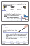
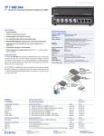
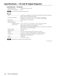
Setup Guide — FOX 4G SW8 Setup Guide — FOX 4G SW8 (cont’d) This sheet provides quick start instructions for an experienced installer to set up and operate the extron FOX 4G SW8 fiber optic switcher. Extron FOX 4G SW8 Fiber Optic Switcher Extron SI 26X Installation Two-way Ceiling Step 1 — Mounting X 4G SW Extron Speakers MPA 122 8 FO Extron FOX 500 Tx T OU Fiber Optic Transmitter 6 IN Rx Mini Power Amplifier LO OP LO T TPU OU OP LO A 122 MP TS TPU s OU Ohm 4/8 OP LO 1 IN A V 0.3 40 US OP LO C R /60 Hz X 500 Tx 8 Inputs L ICA OPT 2* 1 32 RS-2 THRU PASS LOO UTS IO AUD L INP R Rx M 32 ALAR RS-2 TROL CON 1 Tx LINK NA Tx U P THR UT INP LINK FO FOR NAL DATA RN OPTIO * RETU 2 Rx INP Local Monitor B RGB OR R V PC OPTIONAL FOR * RETURN DATA X 500 INP RGB Input Rx M 32 ALAR RS-2 TROL CON 1 Tx Fiber Optic Receiver FOR NAL DATA RN OPTIO * RETU 2 Rx Extron FOX 500 Tx Fiber Optic Transmitter Flat Panel Display 8 OUT IN Switcher 4 Function Transmit data Receive data Signal ground Controlling Device Ground ( ) Receive (Rx) Transmit (Tx) Receivers OPTICAL 2* 1 OPTICAL 2* 1 LINK ) R Typical FOX 4G SW8 application 2 LINK Gnd ( Rx Tx INP RGB V H LINK Do not tin the wires! L B OR R PC LINK • Connect a host device to the front panel Configuration port via an optional TRS RS-232 cable, part #70-335-01. UTS IO AUD UT G Step 5 — Remote connector Pin TX RX Gnd LOO LINK NA Tx U P THR UT INP RGB 0.3A 40V Hz 100-2 50/60 3 L ICA OPT 2* 1 LINK Audio Input Step 4 — Switched optical output Tx Rx Tx FO 32 RS-2 THRU PASS Audio Input RS-232 DVI Output Extron FOX 500 DVI RGB Input Connect up to seven fiber cables between the FOX switcher’s Loop LC connectors (the left-hand connector on transceiver blocks 1 through 7) and compatible receiver(s) for unswitched outputs (each input loops through to its associated output only). • Connect a host device to the rear panel RS-232 port. 10V /MU VOL L 50 H 7 L TE R G LOOP IN REM INP L ER POW UT Connect a fiber cable between the FOX switcher’s Output LC connector (the left-hand connector on transceiver block 8) and a compatible receiver. R OTE UTS 0-2 10 RGB Step 3 — Loop optical outputs TS INPU 5 IN LO LO OP 2 IN 0.3A 40V Hz 100-2 50/60 OPTIONAL FOR * RETURN DATA Tx 7 IN OP AL TIC OP 4 IN OP 3 IN LINK LINK Connect up to eight fiber optic transmitters to the FOX switcher’s rear panel Input connectors (the right-hand connector on each transceiver block). Local Monitor Transmitter #8 OPTICAL 1 2* LINK Step 2 — Optical inputs Transmitter #7 OPTICAL 1 2* LINK Turn off or disconnect all equipment power sources and mount the FOX switcher as required. -232 RS 8 IN Bidirectional Step 6 — Power Loop (Local) Application Switched Application Plug a standard IEC power cord between the power connector and a 100 VAC to 240 VAC, 50 or 60 Hz power source. Operation — Select an input Press and release an input button to select that input. The lit button indicates the selected input. Extron USA - West Headquarters +800.633.9876 Inside USA / Canada Only +1.714.491.1500 +1.714.491.1517 FAX Extron USA - East Extron Europe Extron Asia Extron Japan Extron China Extron Middle East +800.633.9876 +800.3987.6673 +800.7339.8766 +81.3.3511.7655 +81.3.3511.7656 FAX +400.883.1568 +971.4.2991800 +971.4.2991880 FAX +1.919.863.1794 +1.919.863.1797 FAX +31.33.453.4040 +31.33.453.4050 FAX +65.6383.4400 +65.6383.4664 FAX Inside USA / Canada Only Inside Europe Only Inside Asia Only Inside China Only +86.21.3760.1568 +86.21.3760.1566 FAX 68-1550-50 Rev. A 02 09