1
DDS 402
Digital Display Scaler
68-555-01 Rev. D
01 05
Precautions
Safety Instructions • English
This symbol is intended to alert the user of important operating and maintenance
(servicing) instructions in the literature provided with the equipment.
This symbol is intended to alert the user of the presence of uninsulated dangerous
voltage within the product's enclosure that may present a risk of electric shock.
Warning
Power sources • This equipment should be operated only from the power source indicated on the
product. This equipment is intended to be used with a main power system with a grounded
(neutral) conductor. The third (grounding) pin is a safety feature, do not attempt to bypass or
disable it.
Caution
Power disconnection • To remove power from the equipment safely, remove all power cords from
the rear of the equipment, or the desktop power module (if detachable), or from the power
source receptacle (wall plug).
Read Instructions • Read and understand all safety and operating instructions before using the
equipment.
Power cord protection • Power cords should be routed so that they are not likely to be stepped on or
pinched by items placed upon or against them.
Retain Instructions • The safety instructions should be kept for future reference.
Servicing • Refer all servicing to qualified service personnel. There are no user-serviceable parts
inside. To prevent the risk of shock, do not attempt to service this equipment yourself because
opening or removing covers may expose you to dangerous voltage or other hazards.
Follow Warnings • Follow all warnings and instructions marked on the equipment or in the user
information.
Avoid Attachments • Do not use tools or attachments that are not recommended by the equipment
manufacturer because they may be hazardous.
Slots and openings • If the equipment has slots or holes in the enclosure, these are provided to
prevent overheating of sensitive components inside. These openings must never be blocked by
other objects.
Lithium battery • There is a danger of explosion if battery is incorrectly replaced. Replace it only
with the same or equivalent type recommended by the manufacturer. Dispose of used batteries
according to the manufacturer's instructions.
Consignes de Sécurité • Français
Avertissement
Ce symbole sert à avertir l’utilisateur que la documentation fournie avec le matériel
contient des instructions importantes concernant l’exploitation et la maintenance
(réparation).
Alimentations• Ne faire fonctionner ce matériel qu’avec la source d’alimentation indiquée sur
l’appareil. Ce matériel doit être utilisé avec une alimentation principale comportant un fil de
terre (neutre). Le troisième contact (de mise à la terre) constitue un dispositif de sécurité :
n’essayez pas de la contourner ni de la désactiver.
Ce symbole sert à avertir l’utilisateur de la présence dans le boîtier de l’appareil de
tensions dangereuses non isolées posant des risques d’électrocution.
Déconnexion de l’alimentation• Pour mettre le matériel hors tension sans danger, déconnectez tous
les cordons d’alimentation de l’arrière de l’appareil ou du module d’alimentation de bureau (s’il
est amovible) ou encore de la prise secteur.
Attention
Lire les instructions• Prendre connaissance de toutes les consignes de sécurité et d’exploitation avant
d’utiliser le matériel.
Conserver les instructions• Ranger les consignes de sécurité afin de pouvoir les consulter à l’avenir.
Respecter les avertissements • Observer tous les avertissements et consignes marqués sur le matériel ou
présentés dans la documentation utilisateur.
Eviter les pièces de fixation • Ne pas utiliser de pièces de fixation ni d’outils non recommandés par le
fabricant du matériel car cela risquerait de poser certains dangers.
Protection du cordon d’alimentation • Acheminer les cordons d’alimentation de manière à ce que
personne ne risque de marcher dessus et à ce qu’ils ne soient pas écrasés ou pincés par des
objets.
Réparation-maintenance • Faire exécuter toutes les interventions de réparation-maintenance par un
technicien qualifié. Aucun des éléments internes ne peut être réparé par l’utilisateur. Afin
d’éviter tout danger d’électrocution, l’utilisateur ne doit pas essayer de procéder lui-même à ces
opérations car l’ouverture ou le retrait des couvercles risquent de l’exposer à de hautes tensions
et autres dangers.
Fentes et orifices • Si le boîtier de l’appareil comporte des fentes ou des orifices, ceux-ci servent à
empêcher les composants internes sensibles de surchauffer. Ces ouvertures ne doivent jamais
être bloquées par des objets.
Lithium Batterie • Il a danger d'explosion s'll y a remplacment incorrect de la batterie. Remplacer
uniquement avec une batterie du meme type ou d'un ype equivalent recommande par le
constructeur. Mettre au reut les batteries usagees conformement aux instructions du fabricant.
Sicherheitsanleitungen • Deutsch
Vorsicht
Dieses Symbol soll dem Benutzer in der im Lieferumfang enthaltenen
Dokumentation besonders wichtige Hinweise zur Bedienung und Wartung
(Instandhaltung) geben.
Stromquellen • Dieses Gerät sollte nur über die auf dem Produkt angegebene Stromquelle betrieben
werden. Dieses Gerät wurde für eine Verwendung mit einer Hauptstromleitung mit einem
geerdeten (neutralen) Leiter konzipiert. Der dritte Kontakt ist für einen Erdanschluß, und stellt
eine Sicherheitsfunktion dar. Diese sollte nicht umgangen oder außer Betrieb gesetzt werden.
Dieses Symbol soll den Benutzer darauf aufmerksam machen, daß im Inneren des
Gehäuses dieses Produktes gefährliche Spannungen, die nicht isoliert sind und
die einen elektrischen Schock verursachen können, herrschen.
Stromunterbrechung • Um das Gerät auf sichere Weise vom Netz zu trennen, sollten Sie alle
Netzkabel aus der Rückseite des Gerätes, aus der externen Stomversorgung (falls dies möglich
ist) oder aus der Wandsteckdose ziehen.
Achtung
Lesen der Anleitungen • Bevor Sie das Gerät zum ersten Mal verwenden, sollten Sie alle Sicherheits-und
Bedienungsanleitungen genau durchlesen und verstehen.
Aufbewahren der Anleitungen • Die Hinweise zur elektrischen Sicherheit des Produktes sollten Sie
aufbewahren, damit Sie im Bedarfsfall darauf zurückgreifen können.
Befolgen der Warnhinweise • Befolgen Sie alle Warnhinweise und Anleitungen auf dem Gerät oder in
der Benutzerdokumentation.
Keine Zusatzgeräte • Verwenden Sie keine Werkzeuge oder Zusatzgeräte, die nicht ausdrücklich vom
Hersteller empfohlen wurden, da diese eine Gefahrenquelle darstellen können.
Instrucciones de seguridad • Español
Schutz des Netzkabels • Netzkabel sollten stets so verlegt werden, daß sie nicht im Weg liegen und
niemand darauf treten kann oder Objekte darauf- oder unmittelbar dagegengestellt werden
können.
Wartung • Alle Wartungsmaßnahmen sollten nur von qualifiziertem Servicepersonal durchgeführt
werden. Die internen Komponenten des Gerätes sind wartungsfrei. Zur Vermeidung eines
elektrischen Schocks versuchen Sie in keinem Fall, dieses Gerät selbst öffnen, da beim Entfernen
der Abdeckungen die Gefahr eines elektrischen Schlags und/oder andere Gefahren bestehen.
Schlitze und Öffnungen • Wenn das Gerät Schlitze oder Löcher im Gehäuse aufweist, dienen diese
zur Vermeidung einer Überhitzung der empfindlichen Teile im Inneren. Diese Öffnungen dürfen
niemals von anderen Objekten blockiert werden.
Litium-Batterie • Explosionsgefahr, falls die Batterie nicht richtig ersetzt wird. Ersetzen Sie
verbrauchte Batterien nur durch den gleichen oder einen vergleichbaren Batterietyp, der auch
vom Hersteller empfohlen wird. Entsorgen Sie verbrauchte Batterien bitte gemäß den
Herstelleranweisungen.
Advertencia
Este símbolo se utiliza para advertir al usuario sobre instrucciones importantes de
operación y mantenimiento (o cambio de partes) que se desean destacar en el
contenido de la documentación suministrada con los equipos.
Alimentación eléctrica • Este equipo debe conectarse únicamente a la fuente/tipo de alimentación
eléctrica indicada en el mismo. La alimentación eléctrica de este equipo debe provenir de un
sistema de distribución general con conductor neutro a tierra. La tercera pata (puesta a tierra) es
una medida de seguridad, no puentearia ni eliminaria.
Este símbolo se utiliza para advertir al usuario sobre la presencia de elementos con
voltaje peligroso sin protección aislante, que puedan encontrarse dentro de la caja
o alojamiento del producto, y que puedan representar riesgo de electrocución.
Desconexión de alimentación eléctrica • Para desconectar con seguridad la acometida de
alimentación eléctrica al equipo, desenchufar todos los cables de alimentación en el panel trasero
del equipo, o desenchufar el módulo de alimentación (si fuera independiente), o desenchufar el
cable del receptáculo de la pared.
Precaucion
Leer las instrucciones • Leer y analizar todas las instrucciones de operación y seguridad, antes de usar
el equipo.
Conservar las instrucciones • Conservar las instrucciones de seguridad para futura consulta.
Obedecer las advertencias • Todas las advertencias e instrucciones marcadas en el equipo o en la
documentación del usuario, deben ser obedecidas.
Evitar el uso de accesorios • No usar herramientas o accesorios que no sean especificamente
recomendados por el fabricante, ya que podrian implicar riesgos.
Protección del cables de alimentación • Los cables de alimentación eléctrica se deben instalar en
lugares donde no sean pisados ni apretados por objetos que se puedan apoyar sobre ellos.
Reparaciones/mantenimiento • Solicitar siempre los servicios técnicos de personal calificado. En el
interior no hay partes a las que el usuario deba acceder. Para evitar riesgo de electrocución, no
intentar personalmente la reparación/mantenimiento de este equipo, ya que al abrir o extraer las
tapas puede quedar expuesto a voltajes peligrosos u otros riesgos.
Ranuras y aberturas • Si el equipo posee ranuras o orificios en su caja/alojamiento, es para evitar el
sobrecalientamiento de componentes internos sensibles. Estas aberturas nunca se deben obstruir
con otros objetos.
Batería de litio • Existe riesgo de explosión si esta batería se coloca en la posición incorrecta. Cambiar
esta batería únicamente con el mismo tipo (o su equivalente) recomendado por el fabricante.
Desachar las baterías usadas siguiendo las instrucciones del fabricante.
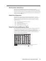
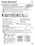
Quick Start — DDS 402
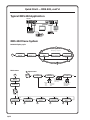
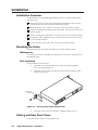
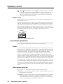
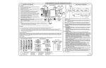
Rear panel video outputs
Installation
RGB or HDTV component video
output (15HD)
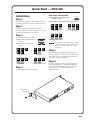
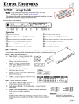
Step 1
Turn off power to the DDS 402 and input and output devices, and remove power cords from them.
RGB or HDTV component video output (6 BNCs)
Step 2
Install four rubber feet on the bottom of the
DDS 402, or mount the DDS to furniture or in a rack
(see figure on the bottom of this page).
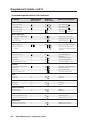
1
Input 1: RGB with buffered local
monitor
G
/Y
H
/HV
V
B
/B-Y
R
/R-Y
G
/Y
H
/HV
V
B
/B-Y
RGsB video
B
/B-Y
R
/R-Y
G
/Y
B
/B-Y
H
V
S
H
V
S
RGBS video
R
/R-Y
G
/Y
B
/B-Y
H
V
S
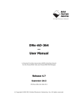
The two video output connectors, the 15HD
connector and the five BNC connectors, both
output the same video signal and the same
sync format.
RGB
R
/R-Y
G
/Y
H
/HV
V
B
/B-Y
RGBS video
RGBHV video
G
/Y
Component video (R-Y, B-Y, Y)
Input 2: RGB or component
video
R
/R-Y
R
/R-Y
RGBHV video
Step 3
Attach input devices to the DDS.
RGB/R-Y, B-Y, Y
R
/R-Y
G
/Y
H
/HV
V
B
/B-Y
Component video (R-Y, B-Y, Y)
Step 4
Attach output devices to the DDS 402.
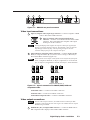
Step 5
Plug the DDS 402 and input and output devices
into a grounded AC source, and turn on the input
and output devices. The figure on the following
page shows a typical application.
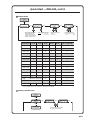
Step 6
Use the LCD menu screens (see the next page) or
RS-232 programming to configure the DDS 402.
See chapter 2 for installation, chapter 3 for front
panel operation, and chapters 4 and 5 for
RS-232 operation.
RE
TE
MO
B -Y
/B
G
/Y
RY
/R
Rack-mount
Bracket
S
V
H
O
U
T
P
U
T
S
RG
B/
R-
Y,
B-
Y, Y
RG
B/
HD
R-
Y,
B-
Y,
Y
B -Y
/B
2
G
/Y
RY
/R
S
V
1
H
Hz
-60
50
V
40
0-2
10
2A
RG
I
N
P
U
T
S
RG
B/
R-
Y,
B-
Y,
Y
B
X
MA
QS-1
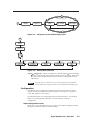
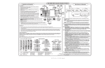
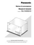
Quick Start — DDS 402, cont’d
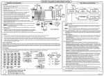
Typical DDS 402 Application
DDS 402
100-240V
50-60Hz
1
2
I
N
T
P
U
T
S
RGB
2A MAX
R
/R-Y
G
/Y
H
/HV
V
O
U
T
P
U
T
S
B
/B-Y
R
/R-Y
G
/Y
B
/B-Y
H
V
S
RGB/R-Y, B-Y, Y
RS-232
RGB/HD R-Y, B-Y, Y
RGB/R-Y, B-Y, Y
RS-232
Control
Plasma Display
PC Computer
Projector
HD Camera
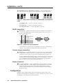
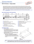
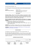
DDS 402 Menu System
Default display cycle
Display Cycle
Extron
DDS 402
Power
on
2
sec.
60-426-01
Version x.xx
Input #2
RGB
2
sec.
Horz. 00.00 kHz
Vert. 00.00 Hz
2
sec.
2
sec.
Output Rate
1024 x 768 @ 60
2
sec.
Main menu
1 Input menu
Power
on
Display
Cycle
Menu
Input
Configuration
Next
Input #2
Betacam 50
Input #2 Phase NEXTNext
016
Next
1
Extron
DDS 402
2 sec.
Input video type
• RGB
• Betacam 50
• YUVi
• Betacam 60
• YUVp
• HDTV
60-426-01
Version x.xx
2
The selected input is
also available for the
pixel phase adjustment
(next screen).
Use either Adjust
knob to set the
slected output’s
pixel phase.
2 sec.
Display
Cycle
MENU
10 sec.
10 sec.
Input
Configuration
1
QS-2
MENU
Output
Configuration
2
10 sec.
Memory
Presets
MENU
3
10 sec.
MENU
Advanced
Configuration
4
10 sec.
Exit
Menu
MENU
5
MENU
NEXT
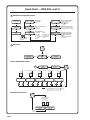
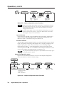
Quick Start — DDS 402, cont’d
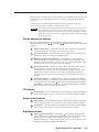
2 Output menu
Input
Configuration
MENU
Output
Configuration
NEXT
Resol 1024 x 768
Refresh @ 60
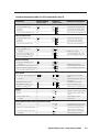
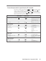
Scaler output resolutions
See the table below for
available combinations of
resolutions and refresh rates.
Output Signal
RGB
NEXT
Scaler output frequencies
Lock = Accu-RATE
Frame Lock™
NOTE
NEXT
Sync Polarity
H Neg
V Neg
NEXT
Polarity combinations
• H-/V- (default) • H+/V• H-/V+
• H+/V+
Output signal format
• RGB
• Y, R-Y, B-Y
Default: 1024x768, 60 Hz
Resolution
50 Hz
640 x 480
800 x 600
75 Hz
X
X
X
X
X
X
X
X
832 x 624
X
X
X
848 x 480
X
X
852 x 480
X
X
X
X
1280 x 768
1280 x 1024
X
85 Hz
*
60 Hz
1024 x 768
56 Hz
Lock at 50/60 Hz*
X
X
X
X
X
X
X
1360 x 765
X
X
1365 x 1024
X
X
X
X
1400 x 1050
X
576p
X
X
720p
HDTV @ 60 Hz only
X
X
1080p
HDTV @ 60 Hz only
X
X
X
X
1080i
X
* The output rate is auto-selected, based on the input.
3 Memory Presets menu
Output
Configuration
MENU
Memory
Presets
NEXT
Save Preset
NA <1> 2
3
NEXT
Erase Preset
1
2 3
<NA>
NEXT
MENU
Advanced
Configuration
Use either Adjust knob to adjust
the settings of the submenus
QS-3
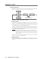
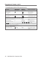
Quick Start — DDS 402, cont’d
4 Advanced Configuration menu
Output
Configuration
Edge Smoothing
OFF <ON>
MENU
NEXT
Advanced
Configuration
Smooth edges
• On (default)
• Off
NEXT
Display blue and sync only
• On
• Off (default)
Blue Mode
OFF <ON>
NEXT
MENU
NEXT
Exit
Menu
Test Pattern
Off
Top Blanking Bot
000
000
RGB Delay
0.7 Seconds
Set top and bottom blanking
• 0 to 237, top and bottom
(Adjust for top,
Adjust for bottom)
RGB delay time (in seconds)
• 0.0 to 5.0 seconds in 0.1 sec.
increments (0.7 second default)
NEXT
Set test pattern type
• Alt Pix
• Off (default)
• Film aspect 1.78
• Color Bars
• Film aspect 1.85
• Crosshatch
• 4 x 4 crosshatch • Film aspect 2.35
• Ramp
• Grayscale
• Crop
NEXT
Use either Adjust
knob to adjust the
submenus
Press and Hold
FREEZE to Reset
NEXT
To reset the scaler, press
and hold the Freeze button
until the reset message
displays.
*Adjust knobs do not affect
this submenu
5 Exit menu
Display
Cycle
NEXT
Advanced
Configuration
MENU
Exit
Menu
MENU
Input
Configuration
Power
on
Extron
DDS 402
2 sec.
60-426-01
Version x.xx
Picture Adjustments menu
CENTER
Horz
Cntr
SIZE
Vert
Horz
Size
BRT/CONT
Vert
Brt
001
Cont
000
2 sec.
ZOOM
DETAIL
Zoom
Horz Filter Vert
001
000
Display
Cycle
10 sec.
timeout
NOTE
The Adjust
knob and the Adjust knob are
used to adjust the image settings on the left and
right sides of the LCD screen, respectively.
Executive Mode menu
Display
Cycle
Press both buttons
simultaneously for
2 seconds
CENTER
Executive Mode
Enabled
10 sec.
timeout
QS-4
ZOOM
Executive Mode
Disabled
Table of Contents
Chapter 1 • Introduction ....................................................................................................... 1-1
About this Manual ............................................................................................................. 1-2
About the Scaler .................................................................................................................. 1-2
Features ................................................................................................................................... 1-3
Chapter 2 • Installation .......................................................................................................... 2-1
Installation Overview ....................................................................................................... 2-2
Mounting the Scaler .......................................................................................................... 2-2
Table use ............................................................................................................................. 2-2
Rack mounting ................................................................................................................... 2-2
Cabling and Rear Panel Views ...................................................................................... 2-2
Video input connections ................................................................................................... 2-3
Video output connections ................................................................................................. 2-3
RS-232 connection ............................................................................................................. 2-4
Contact closure connection ............................................................................................... 2-4
Power connection .............................................................................................................. 2-4
Configuration ....................................................................................................................... 2-4
Chapter 3 • Operation ............................................................................................................. 3-1
Front Panel Controls and Indicators ......................................................................... 3-2
Freeze button ..................................................................................................................... 3-2
Input buttons ..................................................................................................................... 3-2
Selecting an input ........................................................................................................ 3-2
Recalling presets ........................................................................................................... 3-2
Picture adjustment buttons ............................................................................................... 3-3
LCD display ......................................................................................................................... 3-3
Menu control buttons ....................................................................................................... 3-3
Adjustment knobs .............................................................................................................. 3-3
Button icons ....................................................................................................................... 3-4
Front Panel Operations .................................................................................................... 3-4
Power ................................................................................................................................. 3-4
Menu system overview ...................................................................................................... 3-4
Configuration ..................................................................................................................... 3-5
Input Configuration menu ........................................................................................... 3-5
Input #2 submenu ............................................................................................... 3-6
Pixel Phase submenu ........................................................................................... 3-6
Output Configuration menu ........................................................................................ 3-6
Resolution and refresh rates submenu ............................................................... 3-7
Output signal submenu ...................................................................................... 3-7
Sync Polarity submenu ........................................................................................ 3-7
Memory Presets menu .................................................................................................. 3-8
Save Presets submenu ......................................................................................... 3-8
Erase Presets submenu ........................................................................................ 3-8
Digital Display Scaler • Table of Contents
i
Table of Contents, cont’d
Advanced Configuration menu .................................................................................... 3-9
Edge Smoothing submenu .................................................................................. 3-9
Blue Mode submenu ........................................................................................... 3-9
Test Pattern submenu ......................................................................................... 3-9
Blanking submenu .............................................................................................. 3-9
RGB Delay submenu ............................................................................................ 3-9
Reset submenu .................................................................................................. 3-10
Exit menu ................................................................................................................... 3-10
Picture adjustments ......................................................................................................... 3-10
Front panel security lockout (executive mode) .............................................................. 3-11
Optimizing the Video ...................................................................................................... 3-12
Setting up a DVD source ................................................................................................. 3-12
Chapter 4 • Programmer’s Guide ..................................................................................... 4-1
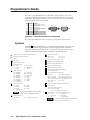
Symbols ................................................................................................................................... 4-2
Scaler-Initiated Messages ............................................................................................... 4-3
Any time ............................................................................................................................. 4-3
Power up ............................................................................................................................ 4-3
Input selection ................................................................................................................... 4-3
Input and output video type ............................................................................................. 4-3
Freeze ................................................................................................................................. 4-3
Picture adjustments ........................................................................................................... 4-3
RGB delay ........................................................................................................................... 4-4
Test pattern ........................................................................................................................ 4-4
Presets ................................................................................................................................ 4-4
Host-to-Scaler Instructions ............................................................................................. 4-5
Scaler Error Responses ..................................................................................................... 4-5
Using the Command/Response Table ........................................................................ 4-5
Command/response table for SIS commands ................................................................... 4-6
Command/response table for special function SIS commands ........................................ 4-9
Chapter 5 • Scaler Software ................................................................................................ 5-1
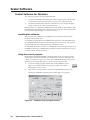
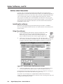
Control Software for Windows .................................................................................... 5-2
Installing the software ...................................................................................................... 5-2
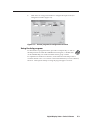
Using the control program ................................................................................................ 5-2
Using the help program .................................................................................................... 5-3
Button-Label Generator ................................................................................................... 5-4
Installing the software ...................................................................................................... 5-4
Using the software ............................................................................................................ 5-4
ii
Digital Display Scaler • Table of Contents
Appendix A • Reference Information .......................................................................... A-1
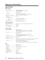
Specifications ....................................................................................................................... A-2
Part Numbers ....................................................................................................................... A-3
Included parts ................................................................................................................... A-3
Suggested part .................................................................................................................. A-3
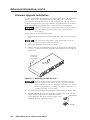
Firmware Upgrade Installation ................................................................................... A-4
Button Labels ....................................................................................................................... A-6
Installing labels in the scaler’s buttons ............................................................................ A-6
Digital Display Scaler • Table of Contents
iii
Table of Contents, cont’d
All trademarks mentioned in this manual are the properties of their respective owners.
iv
Digital Display Scaler • Table of Contents
68-555-01 Rev. D
01 05
Digital Display Scaler
1
Chapter One
Introduction
About this Manual
About the Scaler
Features
Introduction, cont’d
Introduction
About this Manual
This manual contains installation, configuration, and operating information for the
Extron DDS 402 digital display scaler.
This chapter identifies the scaler’s features. Chapter 2 details how to install the
scaler. Chapter 3 describes how to operate the scaler and use all of its features.
Chapter 4 provides information about programming the scaler under RS-232
control, such as from a PC or a host controller. Chapter 5 details the Extron control
software for Windows, which allows you to operate the scaler from a PC in a
graphical environment. Appendix A lists the scaler’s specifications and pertinent
part numbers and provides procedures for performing updates and repairs.
About the Scaler
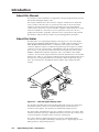
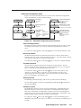
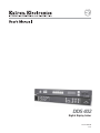
The DDS 402 is a two-input digital display scaler (figure 1-1). The scaler inputs
high-resolution RGBHV/RGBS/RGsB video on a 15HD connector (Input 1) and
either RGBHV/RGBS/RGsB video or component video signals on five BNC
connectors (Input 2). Input 1 is buffered, looped through, and output on a 15HD
connector for use by a local monitor. The DDS 402 scales the selected input up or
down to any 1 of 41 output resolutions and rates and outputs the video as both
RGBHV or RGBS video and HD component video, on five BNCs and a 15HD
connector. Several of the output resolutions and rates include Extron’s Accu-RATE
Frame Lock™ (AFL™), a proprietary technology that locks the output frame rate to
the input rate, solving the problems that result from different input and output
rates. For home theaters, the DDS 402 features HDTV 720p, 1080p, and 1080i
outputs.
RE
RS-232
Control
TE
MO
B Y
/BG
/Y
R
/RY
S
V
H
O
U
T
P
U
T
S
RG
B/R-
Y,
B-
Y, Y
RG
B/HD
R-
Y,
B-
Y,
Y
B Y
/B-
2
G
/Y
R
/RY
S
V
1
H
60H
50100
Extron
DDS 402
0V
-24
2A
MA
z
RG
I
N
P
U
T
S
RG
B/R-
Y,
B-
Y,
Y
Projector
B
X
Plasma
Display
HD Camera
PC Computer
Figure 1-1 — DDS 402 digital display scaler
For upscaling, the DDS 402 converts the horizontal and vertical sync timing and
the number of lines of the lower-resolution RGB input to match the native
resolution of the display. This produces an undistorted, brighter picture.
For downscaling, the DDS 402 accepts any computer resolution, up to 1600 x 1200,
with horizontal scan rates up to 100 kHz and vertical scan rates up to 120 Hz, and
converts the input to match the native resolution of the display.
The scaler is ideal for displaying images on projectors with limited display
resolutions, such as liquid-crystal display (LCD) projectors, digital light processor
(DLP) projectors, and plasma projectors.
1-2
Digital Display Scaler • Introduction
The scaler also features a zoom function, up to 200%, that maintains the original
aspect ratio. The zoom function makes the scaler ideal for video wall applications
using four displays and four DDS 402s zoomed to 200%.
The scaler features four levels of horizontal filters, which help prevent detail loss,
and ten levels of vertical filtering, which reduce flicker.
Other picture controls that the DDS 402 provides are centering, size, brightness,
and contrast adjustments. The scaler also has a top and bottom line blanking
function.
The DDS 402 is housed in a rack-mountable, 1U high, 17.5" wide metal enclosure.
With the included mounting brackets, the scaler can be rack mounted, or mounted
under a desk or table, or against a wall or the side of a desk. The DDS 402 has an
internal 100VAC to 240VAC, 50/60 Hz, 30 watts auto-switchable power supply that
provides worldwide power compatibility.
Features
Inputs — The DDS 402 switches between two inputs: Input 1 accepts computer
video on a 15HD connector, Input 2 accepts high resolution RGBHV, RGBS,
RGsB, or component video on five BNCs.
Computer video loop-through connector — The computer video input, Input 1, is
buffered, looped through, and output for use on a local monitor on a 15HD
connector.
Outputs — The DDS 402 scales images to the following output resolutions:
•
640 x 480 (VGA) at 50 Hz, 60 Hz, 75 Hz, and lock*
•
800 x 600 (SVGA) at 50 Hz, 60 Hz, 75 Hz, and lock*
•
832 x 624 (Macintosh) at 60 Hz and 75 Hz, and lock*
•
848 x 480 (plasma) at 60 Hz and lock*
•
852 x 480 (plasma) at 60 Hz and lock*
•
1024 x 768 (XGA) at 50 Hz, 60 Hz, 75 Hz, 85 Hz, and lock*
•
1280 x 768 (plasma) at 56 Hz and lock*
•
1280 x 1024 (SXGA) at 50 Hz, 60 Hz, and lock*
•
1360 x 765 (plasma) at 60 Hz and lock*
•
1365 x 1024 (plasma) at 60 Hz and lock*
•
1400 x 1050 (SXGA+) at 50 Hz, 60 Hz, and lock*
•
576p (HDTV) at 50 Hz and lock*
•
720p (HDTV) at 60 Hz and lock*
•
1080p (HDTV) at 60 Hz and lock*
•
1080i (HDTV) at 50 Hz, 60 Hz, and lock*
* See Accu-RATE Frame Lock (patent pending) below.
Digital Display Scaler • Introduction
1-3
Introduction, cont’d
Operational flexibility — Operations such as input and scaling selection, picture
controls, and saving and recalling of presets can be performed on the front
panel or over the RS-232 link. The RS-232 link allows remote control via a PC
or control system. Input selection is also available under contact closure
control.
•
Front panel control — The scaler front panel controller supports individual
input selection. The front panel features large, positive touch, illuminated
buttons that can be labeled with text or graphics, two rotary knobs for
making adjustments or selecting menu options, and an LCD.
•
Windows-based control program — Extron’s Windows-based control
program provides a versatile range of operational options with its graphical
interface and drag-and-drop/point-and-click operation.
•
Simple Instruction Set (SIS™) control — The remote control protocol uses
Extron’s SIS for easy programming and operation.
•
Contact closure control — The operator can select either input via contact
closure through the Remote port.
Accu-RATE Frame Lock™ (AFL™) — A technology exclusive to Extron that solves
frame rate conversion issues experienced by video scalers. When video input
and output refresh rates differ, occasionally the two rates cross over each
other. The result is a glitch or image freeze on the display. AFL solves this
problem by locking the output frame rate to the input frame rate.
3:2 pulldown detection for NTSC video sources — This advanced, patent pending,
film mode processing feature helps maximize image detail and sharpness for
video sources that originated from film. When film is converted to NTSC
video, the film frame rate has to be matched to the video frame rate in a
process called 3:2 pulldown. Jaggies and other image artifacts can result if
conventional deinterlacing techniques are used on film-source video. The
DDS 402’s advanced film mode processing recognizes signals that originated
from film. The DDS 402 then applies video processing algorithms that
optimize the conversion of video that was made with the 3:2 pulldown
process. This results in richly detailed images with sharply defined lines.
Test patterns — The switcher features built-in test patterns to aid in monitor or
projector set-up and evaluation.
Blue mode — The switcher can be set to output the blue video signal only, to help
installers calibrate the monitor or projector.
Triple-Action Switching™ (RGB delay) — RGB delay blanks the screen when the
scaler switches between inputs. The new sync signals precede the RGB
signals, so that a noise-filled scramble is not shown during the transition.
The time delay between the RGB and sync signals is user adjustable up to
five seconds on the front panel and under RS-232 control.
Horizontal and vertical detail — The DDS 402 offers four levels of horizontal detail
and eight levels of vertical detail. Horizontal and vertical detail minimize the
loss of picture fidelity.
Picture controls — Horizontal and vertical centering, horizontal and vertical sizing,
brightness, contrast, zoom, and detail controls are available for fine picture
adjustments.
Top and bottom line blanking — Extron’s exclusive variable horizontal blanking
feature allows the operator to add black lines at the top and bottom edges of
the image to mask the top and bottom each image.
1-4
Digital Display Scaler • Introduction
Freeze mode — Locks the output display to the selected image. Once an input is
frozen, the input can be removed without losing the output image. This
feature lets the DDS 402 function as a still store.
Auto memories — The two inputs support 32 auto-recall memories each, based on
the incoming frequency. Information on sizing, centering, detail, contrast,
and brightness is saved.
Front panel security lockout — Locks out all front panel functions except the input
selection and centering controls. When the front panel is locked, all functions
are still available via RS-232 commands.
Mounting flexibility — Mounting brackets make the 1U high scaler mountable in
any conventional 19” wide rack, or under or through a desk or other
furniture.
Power — The 100VAC to 240VAC, auto-switchable, internal power supply of the
DDS 402 provides worldwide power compatibility.
Digital Display Scaler • Introduction
1-5
Introduction, cont’d
1-6
Digital Display Scaler • Introduction
Digital Display Scaler
2
Chapter Two
Installation
Installation Overview
Mounting the Scaler
Cabling and Rear Panel Views
Configuration
Installation, cont’d
Installation
Installation Overview
To install and set up a DDS 402 Digital Display Scaler for operation, perform the
following steps:
1
Disconnect power from all of the equipment, including the video source(s),
and the devices that will receive the scaled video signal.
2
Rack mount the scaler, if desired. See Mounting the Scaler in this chapter.
3
Connect the digital input and loop-through cables. See Video input connections
in this chapter.
4
Connect the digital output cables. See Video output connections in this chapter.
5
If desired, connect the RS-232 cable. See RS-232 connection and Contact closure
connection in this chapter.
6
Connect the AC power cable. See Power connection in this chapter.
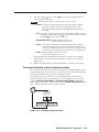
Mounting the Scaler
The DDS 402 comes with rubber feet and a set of rack mounting brackets.
Tabletop use
For tabletop use, attach a self-adhesive rubber foot to each corner of the bottom of
the DDS 402 scaler.
Rack mounting
Rack mount the scaler as follows:
1.
Attach the rack mount brackets to the scaler with eight #8 machine
screws, provided (figure 2-1).
2.
Insert the scaler into the rack, align the holes in the mounting bracket
with those of the rack.
RE
B -Y
/B
G
/Y
RY
/R
Rack-mount
Bracket
V
H
O
U
T
P
U
T
S
Y, Y
Y,
B-
B/R-
RG
RG
B/
HD
R-
Y,
B-
Y,
Y
B -Y
/B
2
G
/Y
RY
/R
S
V
1
H
Hz
-60
50
V
40
0-2
10
2A
RG
I
N
P
U
T
S
RG
B/
R-
Y,
B-
Y,
Y
B
X
MA
Figure 2-1 — Mounting the digital display dcaler
3.
Secure the scaler to the rack using the supplied machine screws.
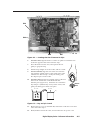
Cabling and Rear Panel Views
All connectors are on the rear panel (figure 2-2).
2-2
Digital Display Scaler • Installation
S
TE
MO
7
100-240V
1
50-60Hz
3
1
5
6
2
I
N
P
U
T
S
2A MAX
4
RGB
R
/R-Y
G
/Y
H
/HV
V
O
U
T
P
U
T
S
B
/B-Y
R
/R-Y
G
/Y
B
/B-Y
H
V
S
RGB/R-Y, B-Y, Y
REMOTE
RGB/HD R-Y, B-Y, Y
RGB/R-Y, B-Y, Y
2
Figure 2-2 — DDS 402 rear panel connectors
Video input connections
1
Input 1 (computer video) input (top) connector — Connect computer or RGB
video to this female 15HD connector.
1
2
RGB
Input 1 (computer video) loop-through (bottom)
connector — Connect a local monitor to this female 15HD
connector. The scaler buffers the computer video input
and loops it on this connector.
The Digital Display Scaler buffers the computer video input signal before
passing it to the loop-through connector. Beyond that, it does not alter the
loop-through video in any way. The loop through output is the same
resolution and frequency as the computer video input.
3
Input 2 (RGB or component video) connectors — Connect RGBHV, RGBS,
RGsB, or component video (R-Y, Y, B-Y for YUVi or YUVp, or Betacam) to
these female BNC connectors (figure 2-3).
Ensure that the correct Input 2 video format is selected from the front panel
menu, see Input #2 submenu, in chapter 3, Operation, or via the RS-232
port, see chapter 4, Programmer’s Guide, and chapter 5, Scaler Software.
R
/R-Y
G
/Y
H
/HV
V
B
/B-Y
G
/Y
H
/HV
V
G
/Y
H
/HV
V
B
/B-Y
RGBS video
RGBHV video
R
/R-Y
R
/R-Y
B
/B-Y
RGsB video
R
/R-Y
G
/Y
H
/HV
V
B
/B-Y
Component video (R-Y, B-Y, Y)
Figure 2-3 — Input 2 connections for RGBHV, RGBS, RGsB and
component video
For RGBHV video — Connect to five BNC connectors.
For RGBS video — Connect to four BNC connectors.
For RGsB and component video — Connect to three BNC connectors.
Video output connections
The two video output connectors, the 15HD connector and the five BNC
connectors, both output the same video signal. The 15HD connector outputs
RGBHV only, not RGBS.
4
RGB/HD R-Y, B-Y, Y Output 15HD connector — Connect an RGB video or
HD component video display to this female 15HD connector.
Digital Display Scaler • Installation
2-3
Installation, cont’d
5
RGB/HD R-Y, B-Y, Y Output BNC connectors — Connect an RGB video or
HD component video display to these female BNC connectors (figure 2-4).
R
/R-Y
G
/Y
B
/B-Y
R
/R-Y
G
/Y
B
/B-Y
R
/R-Y
G
/Y
B
/B-Y
H
V
S
H
V
S
H
V
S
Component video (R-Y, B-Y, Y)
RGBS video
RGBHV video
Figure 2-4 — BNC output connections for RGBHV, RGBS, and component
video
For RGBHV video — Connect to five BNC connectors.
For RGBS video — Connect to four BNC connectors.
For component video — Connect to three BNC connectors.
RS-232 connection
6
Remote port — Connect a host device, such as a computer or touch panel
control, to the Digital Display Scaler via this 9-pin D connector for serial
RS-232 control (figure 2-5).
Pin
1
2
3
4
5
6
7
8
9
RS-232
—
TX
RX
—
Gnd
—
—
—
—
Function
Contact closure, input #1
Transmit data
Receive data
Contact closure, input # 2
Signal ground
Not used
Not used
Not used
Not used
5
1
9
6
Female
1
5
6
9
Male
Figure 2-5 — Remote port pin assignments
See chapter 4, Programmer’s Guide, for definitions of the SIS commands and
chapter 5, Scaler Software to install and use the control software.
Contact closure connection
6
Remote port — The Remote connector also provides a way to select an input
using a remote contact closure device. Contact closure control uses pins on
the Remote connector that are not used by the RS-232 interface (figure 2-5).
To select a different input number using a contact closure device, momentarily
short the pin for the desired input number to logic ground (pin 5). To force
one of the inputs to be always selected, leave the short to logic ground in
place. The short overrides front panel input selections.
Power connection
7
AC power connector — Plug a standard IEC power cord into this connector
to connect the scaler to a 100 to 240VAC, 50 Hz or 60 Hz power source. The
front panel control and input selection buttons light in sequence during
power-up, the LCD displays the product name and then cycles through the
default messages.
Configuration
DDS 402 can be configured using either the front panel controls, the SIS, or the
Windows Control program. See chapter 3, Operation, chapter 4, Programmer’s Guide,
and chapter 5, Scaler Software for more information.
2-4
Digital Display Scaler • Installation
Digital Display Scaler
3
Chapter Three
Operation
Front Panel Controls and Indicators
Front Panel Operations
Optimizing the Video
Operation, cont’d
Operation
Front Panel Controls and Indicators
All of the Digital Display Scaler’s controls and indicators are on the front panel
(figure 3-1). The large, positive-touch, illuminated push buttons can be labeled
with text and/or graphics. The buttons are fully illuminated green, amber, or red
when selected. The 16x2 LCD display indicates the switcher status, and displays
menu selections, the data rate, and the status of additional system features.
INPUTS
FREEZE
RGB
RGB
R-Y, B-Y, Y
1
2
PICTURE ADJUSTMENTS
CENTER
SIZE
BRT/CONT
ZOOM
ADJUST
DETAIL
MENU
NEXT
DDS 402
DIGITAL DISPLAY SCALER
1
2
3
4
5
6
7
8
9
10 11 12
13
Figure 3-1 — Front panel, digital display scaler
Freeze button
1
Freeze button — The Freeze button locks the output display to the current
image being input. When the freeze function is enabled, the button is lit. To
unfreeze the image, press the Freeze button again.
When the image is frozen, the Freeze button lights red. When the freeze
function is deselected, the Freeze button returns to unlit.
When an input is frozen, the video input can be removed without losing the
display image.
If the other input is then selected, the switching action deselects the Freeze
function, the frozen image is lost, and the Freeze button returns to its unlit
state.
Input buttons
Each input button selects an input to scale and output. The buttons also select
memory presets. The presets, up to three for each input, are stored values of the
user-selectable centering and sizing settings.
The Input 2 video format, resolution, and frequency must be identified using
either the front panel menus, the SIS, or the Windows Control program. See
Front Panel Operations in this chapter, chapter 4, Programmer’s Guide,
and chapter 5, Scaler Software, for more information.
Selecting an input
2
Input 1 button — The Input 1 button selects RGB computer video from input 1
(the 15HD input connector).
3
Input 2 button — The Input 2 button selects RGB video, YUVi, YUVp,
Betacam 50, Betacam 60, or HDTV component video from input 2 (the 5 BNC
input connectors).
Recalling presets
As a secondary function the Input 1 and Input 2 buttons, 2 and 3 , select one of up
to three memory presets to recall for the selected input. To recall an input 1 preset,
with input 1 already selected, press the Input 1 button repeatedly to select the
desired preset. The available presets are selected sequentially in a loop: {press}
preset 1, {press} preset 2, {press} input 3, {press} input 1, and so on. Select an input
2 preset by pushing the Input 2 button repeatedly.
Memory presets are created using the Memory Presets menu. See Memory Presets
menu in this chapter for instructions on creating a preset.
3-2
Digital Display Scaler • Operation
Memory presets with no values saved in them are not included in the loop; if preset
2 is empty, the loop sequences from preset 1 to preset 3 when the Input button is
pressed.
As each preset is recalled, the LCD displays the message Input x Memory y,
where x is the input (1 or 2) and y is the preset (1, 2, or 3).
The centering and sizing adjustments are tailored for the selected output rate.
If you change the output rate and then recall a preset for the earlier rate, the
adjustments recalled in the preset have no effect on the video output. However,
if you then change back to the earlier output rate, the affects of the adjustments
appear on the screen.
Picture adjustment buttons
The picture adjustment buttons select individual image adjustments that are
adjusted using the Adjust ( 12 ) and Adjust ( 13 ) knobs. These buttons light when
pressed.
4
Center control button — The Center button selects and deselects the display
centering adjustment. See Picture adjustments in this chapter.
5
Size control button — The Size button selects and deselects the display size
adjustment. See Picture adjustments in this chapter.
6
Brightness/Contrast control button — The Brightness/Contrast button
selects and deselects the display brightness and contrast adjustments. The
brightness adjustment range is from 0 to 127. The contrast adjustment range
is from 0 to 255. See Picture adjustments in this chapter.
7
Zoom control button — The Zoom button selects and deselects the display
zoom adjustment. Zoom works the centering and sizing functions
simultaneously to enlarge a portion of the displayed image. Turning either
Adjust knob clockwise zooms in on the image, and turning either knob
counterclockwise zooms out from the image. See Picture adjustments in this
chapter.
8
Detail control button — The Detail button selects and deselects the display
image detail (sharpness) adjustment. The sharpness adjustment compensates
for long cable runs. The Adjust knob controls the horizontal filter and the
Adjust knob controls the vertical filter. The adjustment range for each filter
is 0 to 7. See Picture adjustments in this chapter.
LCD display
9
Status display — The 16-column by 2-line LCD displays configuration menus
and status information. See Front Panel Operations in this chapter for details.
Menu control buttons
10
Menu button — The Menu button enters and moves through the main menu
system in the DDS 402. See Front Panel Operations in this chapter for details.
11
Next button — The Next button steps through the submenus in the DDS 402
menu system. See Front Panel Operations in this chapter for details.
Adjustment knobs
12
Adjust (horizontal) knob — The Adjust
knob changes settings when
used in conjunction with the picture adjustment buttons or the menu system.
Rotate this knob to change picture settings when one of the picture
adjustment buttons is selected. In the menu system, rotate this knob to scroll
through menu options and make adjustments.
Digital Display Scaler • Operation
3-3
Operation, cont’d
13
Adjust (vertical) knob — The Adjust knob changes settings when used in
conjunction with the picture adjustment buttons or the menu system. Rotate
this knob to change picture settings when one of the picture adjustment
buttons is selected. In the menu system, rotate this knob to scroll through
menu options and make adjustments.
Button icons
The translucent covers on the push buttons can be removed and replaced to insert
labels behind the covers.
Input and output labels can be created easily with Extron’s Button Label Generator
software, which ships with every Extron DDS 402. Each input and output can be
labeled with names, alphanumeric characters, or even color bitmaps for easy and
intuitive input and output selection (figure 3-2). See chapter 5, Scaler Software, for
details on using the label software. See Appendix A, Reference Information, for blank
labels and procedures for removing and replacing the translucent covers.
INPUTS
RGB
RGB
R-Y, B-Y, Y
Computer
DVD
Figure 3-2 — Sample button icons
Front Panel Operations
The following paragraphs detail the power-up process and then describe the menu
system, the picture adjustments, and selection of executive mode.
Power
Power is automatically applied when the power cord is connected to an AC source.
When AC power is applied, the scaler performs a self-test that lights all of the front
panel button indicators and then defaults to the selected input (lit). The Menu and
Next buttons also light. The self-test also displays the model name and the
firmware version in the LCD display. After approximately 2 seconds, the LCD
reverts to its default display, cycling through displays of the selected input, the
input rate, and the selected output rate (figure 3-3). An error-free power up self-test
sequence leaves all of the button indicators, with the exception of the selected input,
Menu, and Next pushbuttons, unlit and the LCD displaying the default display cycle.
The selected input, the picture adjustments, and other current settings are saved in
non-volatile memory. When power is applied, the latest configuration is retrieved.
If an error occurs during the self-test, the switcher locks up and will not operate. If
your switcher locks up on power-up, call the Extron S3 Sales & Technical Support
Hotline.
Menu system overview
Figure 3-4 shows a flowchart of the main menus in the menu system.
Menu button — Press the Menu button to activate the menu system and to scroll
through the five main menus.
Next button — Press the Next button to move between the submenus of a selected
main menu and to activate one for viewing or configuration. Pressing the
Next button while in the input configuration menu causes the current input’s
number and format type to be displayed on the LCD.
3-4
Digital Display Scaler • Operation
Display Cycle
Extron
DDS 402
Power
on
60-426-01
Version x.xx
2
sec.
Input #2
RGB
2
sec.
2
sec.
Horz. 00.00 kHz
Vert. 00.00 Hz
2
sec.
Output Rate
1024 x 768 @ 60
2
sec.
Figure 3-3 — LCD power up and default display cycle
Power
on
Extron
DDS 402
2 sec.
60-426-01
Version x.xx
2 sec.
Display
Cycle
MENU
10 sec.
Input
Configuration
MENU
10 sec.
Output
Configuration
10 sec.
MENU
Memory
Presets
10 sec.
MENU
Advanced
Configuration
10 sec.
MENU
Exit
Menu
NEXT
MENU
Figure 3-4 — Menu system flowchart
Adjust and knobs — When in a submenu, rotate the Adjust knob and Adjust
knob to scroll through the submenu options and select a setting. Refer to the
flowcharts in this chapter and to specific sections for explanations on knob
adjustments.
From any menu or submenu, after ten seconds of inactivity, the DDS 402
saves all adjustment settings and times-out to the default LCD display cycle.
Configuration
The DDS 402 can be configured using either the menu system and front panel
controls, the SIS, or the Windows Control program. See chapter 4, Programmer’s
Guide, and chapter 5, Scaler Software.
Use the Menu button to scroll through and select the main menus. Use the Next
button to scroll through the submenus of a main menu for viewing or
configuration.
Input Configuration menu
Figure 3-5 is a flowchart that shows an overview of the Input Configuration menu,
the Input #2 submenu, and the available settings.
Digital Display Scaler • Operation
3-5
Operation, cont’d
Display
Cycle
Input
Configuration
Menu
Input #2
Betacam 50
Next
Input #2 Phase NEXTNext
016
Next
1
Input video type
• RGB
• Betacam 50
• YUVi
• Betacam 60
• YUVp
• HDTV
2
The selected input is
also available for the
pixel phase adjustment
(next screen).
Use either Adjust
knob to set the
slected output’s
pixel phase.
Figure 3-5 — Input Configuration menu flowchart
If you press the Menu button while a main menu or a submenu is active, the
next main menu becomes active. For example, the display changes from the
Input Configuration main menu or the Input #2 submenu to the Output
Configuration main menu.
To return to the default screens, let the DDS 402 remain idle for 10 seconds
until the selected screen times out, or press the Menu button until the Exit
Menu appears, then press the Next button.
Input #2 submenu
Rotate either the Adjust or the Adjust knob while in the Input #2 submenu to
select the correct video format (RGB, YUVi, YUVp, Betacam 50, Betacam 60, or
HDTV) for input 2. The default for input 2 is Betacam 60.
Pixel Phase submenu
The Pixel Phase submenu displays and lets you set the pixel phase for the selected
input. Pixels phase is the timing of the digital scaler’s sampling. Sampling at the
optimum pixel phase reduces noise and results in a clear and sharp image.
Rotate either the Adjust or the Adjust knob to select the pixel phase for the
selected input from 0 to 31. You can select the unselected input while this screen is
active by pressing the desired Input button. The default is 16.
The pixel phase adjustment for input 2 is only available when the input type is
set to RGB, YUVp, or HDTV.
Output Configuration menu
Figure 3-6 is a flowchart that shows an overview of the Output Configuration
menu, the submenus, and the available settings.
Input
Configuration
MENU
Output
Configuration
NEXT
Resol 1024 x 768
Refresh @ 60
NEXT
Output Signal
RGB
NEXT
Sync Polarity
H Neg
V Neg
NEXT
MENU
Memory
Presets
Scaler output resolutions
See the table on the
opposite page for available
combinations of resolutions
and refresh rates.
Scaler output frequencies
NOTE
Lock = Accu-RATE
Frame Lock™
Output signal format
• RGB
• Y, R-Y, B-Y
Default: 1024x768, 60 Hz
Figure 3-6 — Output Configuration menu flowchart
3-6
Digital Display Scaler • Operation
Polarity combinations
• H-/V- (default) • H+/V• H-/V+
• H+/V+
Resolution and refresh rates submenu
Rotate the Adjust knob while in this submenu to select one of the available
output resolutions.
Rotate the Adjust knob while in this submenu to select one of the available refresh
™
(vertical scanning) rates. Selecting Lock enables the Extron Accu-RATE Frame Lock
™
(AFL ) feature. Accu-RATE Frame Lock eliminates image tearing and other
artifacts of scaling motion video by eliminating frame rate conversion. It exactly
matches the output rate of the DDS 402’s scaler to the frame rate of the selected
input. Select this feature if you will be using motion video sources with a display
that is capable of a variety of refresh rates.
The default resolution and refresh rate is 640 x 480 @ 60 Hz.
Resolution
50 Hz
640 x 480
800 x 600
75 Hz
X
X
X
X
X
X
X
X
832 x 624
X
X
X
848 x 480
X
X
852 x 480
X
X
X
1280 x 768
1280 x 1024
X
X
X
X
85 Hz
Lock at 50/60 Hz*
60 Hz
1024 x 768
56 Hz
X
X
X
X
X
1360 x 765
X
X
1365 x 1024
X
X
X
X
1400 x 1050
X
576p
X
X
720p
HDTV @ 60 Hz only
X
X
1080p
HDTV @ 60 Hz only
X
X
X
X
1080i
X
* The output rate is auto-selected, based on the input.
Output Signal submenu
Rotate the either Adjust or the Adjust knob counter clockwise while in this
submenu to select RGB video. Rotate the knob clockwise to select component (Y,
R-Y, B-Y) video for output.
Sync Polarity submenu
The display or projector may require a particular combination of horizontal (H) and
vertical (V) sync signal polarities. Select the appropriate combination of positive or
negative H and V sync by rotating either the Adjust or the Adjust knob.
Digital Display Scaler • Operation
3-7
Operation, cont’d
Memory Presets menu
Figure 3-7 is a flowchart that shows an overview of the Memory Presets menu, the
Save Presets and Erase Presets submenus, and the available settings.
Output
Configuration
MENU
Memory
Presets
NEXT
Save Preset
NA <1> 2
3
NEXT
Erase Preset
1
2 3
<NA>
NEXT
MENU
Advanced
Configuration
Use either Adjust knob to adjust
the settings of the submenus
Figure 3-7 — Memory Presets menu flowchart
Save Presets submenu
Rotate either the Adjust or the Adjust knob while in the Save Presets submenu
to select (< >) one of three memory presets for the selected input or no preset. Press
the Next button to save the current settings to the selected preset. Select N/A and
press the Next button to exit without saving the settings.
Presets, saved values of the current centering and sizing settings, are saved in nonvolatile memory; when the DDS 402 is powered down and later powered back up,
the settings are available for selection. Saving the settings to a preset overwrites the
settings previously written to that preset.
The centering and sizing adjustments are tailored for the selected output rate.
If you change the output rate and then recall a preset for the earlier rate, the
adjustments recalled in the preset have no effect on the video output. However,
if you then change back to the earlier output rate, the affects of the adjustments
appear on the screen.
Memory presets are recalled using the Input buttons menu. See Input buttons in this
chapter for instructions on recalling a preset.
Erase Presets submenu
Rotate either the Adjust or the Adjust knob while in the Erase Presets submenu
to select (< >) one of three memory presets to erase. Press the Next button to erase
the preset.
3-8
Digital Display Scaler • Operation
Advanced Configuration menu
Figure 3-8 is a flowchart that shows an overview of the Advanced Configuration
menu, the submenus, and the available settings.
Output
Configuration
Edge Smoothing
OFF <ON>
MENU
NEXT
Advanced
Configuration
NEXT
Blue Mode
OFF <ON>
MENU
NEXT
Exit
Menu
Test Pattern
Off
NEXT
Use either Adjust
knob to adjust the
submenus
Smooth edges
• On (default)
• Off
Top Blanking Bot
000
000
NEXT
Display blue and sync only
• On
• Off (default)
RGB Delay
0.7 Seconds
Set top and bottom blanking
• 0 to 237, top and bottom
(Adjust for top,
Adjust for bottom)
RGB delay time (in seconds)
• 0.0 to 5.0 seconds in 0.1 sec.
increments (0.7 second default)
NEXT
Set test pattern type
• Alt Pix
• Off (default)
• Film aspect 1.78
• Color Bars
• Film aspect 1.85
• Crosshatch
• 4 x 4 crosshatch • Film aspect 2.35
• Ramp
• Grayscale
• Crop
Press and Hold
FREEZE to Reset
NEXT
To reset the scaler, press
and hold the Freeze button
until the reset message
displays.
*Adjust knobs do not affect
this submenu
Figure 3-8 — Advanced Configuration menu flowchart
Edge Smoothing submenu
The Edge Smoothing submenu turns the edge smoothing feature on and off. Edge
smoothing smooths edges of a picture by minimizing the differences between
pixels.
Use either the Adjust
knob or the Adjust knob to select On (the default) or Off.
Blue Mode submenu
The Blue Mode submenu turns the blue mode feature on and off. Blue mode is
helpful in the setup of the connected displays’ monitors. In the blue mode, only the
sync and blue video signals are passed to the display.
Use either the Adjust
knob or the Adjust knob to select On or Off (the default).
Test Pattern submenu
The Test Pattern submenu selects from among several test patterns. The test
patterns are helpful when adjusting the connected displays for color, convergence,
focus, resolution, contrast, grayscale, and aspect ratio.
Use either the Adjust knob or the Adjust knob to select a test pattern. The
options are: Off, Color Bars, Crosshatch, 4 x 4 Crosshatch, Grayscale, Crop,
Alternating Pixels, Film Aspect Ratio 1.78, Film Aspect Ratio 1.85, Film Aspect
Ratio 2.35, and Ramp. The default is Off.
Blanking submenu
The Blanking submenu displays and sets the top and bottom line blanking.
Use the Adjust knob to adjust the top blanking and the Adjust knob to adjust
the bottom blanking.
RGB Delay submenu
The RGB Delay submenu displays and sets the RGB delay. With RGB delay, the
DDS 402 switches to the new sync signal before switching RGB (video) signals.
This allows a brief delay for the displays to adjust to the new sync timing before
displaying the new picture, which will appear without glitches. RGB delay is also
known as Triple-Action Switching or video mute switching.
Use either the Adjust knob or the Adjust knob to select the blanking period
(RGB delay time) from 0 seconds to 5 seconds in 0.1 second steps. The default is 0.7
seconds.
Digital Display Scaler • Operation
3-9
Operation, cont’d
Reset submenu
The Reset submenu resets the DDS 402 to the default values. Reset the scaler by
pressing and holding the Freeze button while this submenu is
Unit Reset to
active. The LCD displays Unit Reset to Factory Defaults when the
Factory Defaults
reset is complete. Release the Freeze button.
Exit menu
From the Exit menu (figure 3-9), press the Next button to return to the default
display cycle, or press the Menu button to return to the Input Configuration menu.
Display
Cycle
NEXT
Advanced
Configuration
Exit
Menu
MENU
MENU
Input
Configuration
Figure 3-9 — Exit menu flowchart
Picture adjustments
The picture adjustments allow you to fine tune the image quality of the selected
input. When one of the Picture Adjustments buttons (Center, Size, Brightness and
Contrast, Zoom, or Detail) is pressed, the corresponding image adjustment menu
appears on the LCD screen. Adjustments can then be made by rotating the
Adjust knob or the Adjust knob. Picture adjustment settings are stored in nonvolatile memory; when the scaler is powered down and powered up, the settings
are restored.
Adjust an image for centering, sizing, brightness, contrast, color, tint, zoom, or
detail as follows (figure 3-10):
Power
on
CENTER
Horz
Cntr
SIZE
Vert
Horz
Size
Extron
DDS 402
BRT/CONT
Vert
Brt
001
Cont
000
2 sec.
60-426-01
Version x.xx
2 sec.
ZOOM
DETAIL
Zoom
Horz Filter Vert
001
000
Display
Cycle
10 sec.
timeout
NOTE
The Adjust
knob and the Adjust knob are
used to adjust the image settings on the left and
right sides of the LCD screen, respectively.
Figure 3-10 — Picture adjustments flowchart
1.
3-10
Press the appropriate picture adjustment button: centering (Center), sizing
(Size), brightness and contrast (Brt/Cont), zoom, or detail. The LCD display
shows the name of the adjustment and the value of the current setting.
Digital Display Scaler • Operation
2.
Rotate the Adjust knob or Adjust knob to vary the settings within the
following adjustment ranges:
The Adjust knobs have no mechanical limits to their rotation.
• Center: No ranges are displayed for the Center adjustments. Rather,
observe the display and turn the Adjust knob to adjust
horizontal centering and the Adjust knob to adjust vertical
centering.
• Size: No ranges are displayed for the Size adjustments. Rather, observe
the display and turn the Adjust knob to adjust horizontal size and
the Adjust knob to adjust vertical size.
• Brightness/Contrast: Brightness adjusts from 0 to 64.
Contrast adjusts from 0 to 255.
• Zoom: No ranges are displayed for the Zoom adjustments. Rather,
observe the display and turn either Adjust knob clockwise (to
zoom in) or counterclockwise (to zoom out). The image increases
or decreases in size both the horizontal and vertical dimensions.
• Detail: Horizontal (Horz) adjusts from 0 to 7.
Vertical (Vert) adjusts from 0 to 7.
The DDS 402 picture adjustment functions time-out after 10 seconds; the
adjustments are activated and saved and the LCD returns to the default
display cycle.
3.
Repeat steps 1 and 2 for each image adjustment to be made for that input.
Front panel security lockout (executive mode)
The front panel security lockout limits the operation of the Digital Display Scaler
from the front panel. When the scaler’s front panel is locked, all of the front panel
functions are disabled except for Freeze and input selection.
To toggle the security lockout on or off, press and hold the Center and Zoom
buttons simultaneously for approximately two seconds (figure 3-11). The LCD
displays Executive Mode Enabled or Executive Mode Disabled to indicate the
mode. Release the buttons. The LCD also displays Executive Mode Enabled if you
push a locked out button when the scaler is locked.
Display
Cycle
Press both buttons
simultaneously for
2 seconds
CENTER
Executive Mode
Enabled
ZOOM
Executive Mode
Disabled
10 sec.
timeout
Figure 3-11 — Executive mode flowchart
Digital Display Scaler • Operation
3-11
Operation, cont’d
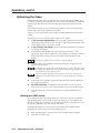
Optimizing the Video
Perform the following steps, in sequence, after you have installed the DDS. This
procedure will help you to configure the scaler for the best settings for your display
environment. In a multi-screen environment, perform this procedure for each
display.
See Advanced Configuration menu earlier in this chapter to select and output a test
pattern and to select and output blue only video.
See Picture adjustments, earlier in this chapter, to make adjustments to the picture
quality.
See Memory Presets menu, earlier in this chapter to save presets.
1.
If you are using a digital display, such as an LCD or DLP projector, use the
alternating pixels test pattern as a reference to adjust the phase and dot clock
on the display devices. Proceed to step 3.
2.
If you are using a CRT display, use the cross hatch test pattern as a reference
to converge the display.
3.
Set the DDS to output either the crop test pattern for 4:3 video or the
appropriate aspect ratio test pattern. Use the display’s positioning controls to
position the image so that you can see all sides of the test pattern on the
display.
Do not use the DSS’s center controls to position the image.
4.
Select an input. Use the DSS’s size and center functions to fill the crop or
aspect ratio test pattern.
If the input source is a DVD, set the DVD player to output a 16:9 aspect ratio,
see Setting up a DVD source below, before sizing the image using the DSS’s
size function to correct the aspect ratio.
When sizing and centering a letterbox movie video source, increasing the
brightness on the DDS makes it easier to see the top and bottom of the active
video.
5.
If the input source is RGB, use the horizontal and vertical detail adjustments
to increase the sharpness.
6.
For RGB video inputs, set brightness and contrast levels. See Color/Tint,
Brightness/Contrast, Size, Center, and Detail adjustments, earlier in this chapter.
7.
Save this setting into one of the user memories using the DDS Memories
menu.
Setting up a DVD source
To get the best results when using a DVD as a video source, Extron recommends
that the DVD player itself be set up to output an aspect ratio of 16:9 and not 4:3.
Because all DVDs are mastered as 16:9, having them set up for anything else causes
the player to internally scale and compress the signal.
All sizing adjustments to correct aspect ratio should be done using the DDS.
To change the output aspect ratio of most DVD players:
3-12
1.
Enter the DVD player’s setup or action menu while the disc is stopped.
2.
Select the 16:9 aspect ratio.
Digital Display Scaler • Operation
Digital Display Scaler
4
Chapter Four
Programmer’s Guide
Symbols
Scaler-Initiated Messages
Host-to-Scaler Instructions
Scaler Error Responses
Using the Command/Response Table
Command/Response Table for SIS Commands
Command/Response Table for Special Function SIS Commands
Programmer’s Guide
The scaler’s rear panel Remote 9-pin D female connector (figure 4-1) can be
connected to the RS-232 serial port output of a host device such as a computer
running the HyperTerminal utility or a control system. This connection makes
software control of the scaler possible.
Pin
1
2
3
4
5
6
7
8
9
RS-232
—
TX
RX
—
Gnd
—
—
—
—
Function
Contact closure, input #1
Transmit data
Receive data
Contact closure, input # 2
Signal ground
Not used
Not used
Not used
Not used
5
1
1
9
6
Female
5
6
9
Male
Figure 4-1 — Remote connector pin arrangement
The protocol is 9600 baud, 8-bit, 1 stop bit, no parity, and no flow control.
Symbols
Symbols ( Xn values), defined below, are used throughout the discussions of the
switcher-initiated messages that begin on the next page and the command/
response table that begins on page 4-6. The symbols represent variables in the
switcher-initiated messages and the command/response table fields.
= CR/LF (carriage return/line feed) (hex 0D 0A)
•
Esc
X1
X2
02 = H+/V–
03 = H+/V+
= On/off status (0 = off, 1 = on)
= Input number (1 or 2)
X8
= Brightness value (000 thru 063)
= Input video type:
X9
= Contrast value (000 thru 255)
X10
= Filter value (000 thru 007)
X11
= Blanking value (0 thru 237)
X12
= Pixel sampling phase (00 through 31)
X13
= RGB delay (00 to 50)
X14
= Test pattern type (1 through 10)
3 = Betacam 50
4 = Betacam 60
5 = HDTV
= Scaler resolution:
=
=
=
=
=
=
=
=
640x480
800x600
832x624
848x480
852x480
1024x768
1280x768
1280x1024
08
09
10
11
12
13
14
=
=
=
=
=
=
=
1360x765
1365x1024
1400 x 1050
576p
720p
1080p
1080i
= Scaler refresh rate
00
01
02
*
= 50 Hz
= 56 Hz*
= 60 Hz
1280 x 768 only
03 = 75 Hz
04 = 85 Hz
05 = Lock
000 = off
001 = Color Bars
002 = crosshatch
003 = 4x4 crosshatch
004 = grayscale
005 = crop
X15
= Input configuration preset (01 through 03)
X16
= nnn.nn where
Hrt = horizontal rate (kHz)
Vrt = vertical rate (Hz)
X17
= Output video type:
00 = RGB
4-2
006 = alternating pixels
007 = film aspect ratio 1.78
008 = film aspect ratio 1.85
009 = film aspect ratio 2.35
010 = ramp
xxx:xx means signal out of range
Lock is Accu-RATE Frame Lock (AFL) —
50 Hz (PAL) or 59.94 Hz (NTSC) .
X5
00 = H–/V–
01 = H–/V+
X7
00
01
02
03
04
05
06
07
X4
= Output sync polarity:
= Escape key
0 = RGB
1 = YUVi
2 = YUVp
X3
X6
= Carriage return (no line feed)
= Space
01 = Component (Y, R-y, B-y)
Digital Display Scaler • Programmer’s Guide
= Detected input signal standard (0 through 4)
0 = none
1 = NTSC 3.58
2 = PAL
3 = NTSC 4.43
4 = SECAM
– = not applicable
– occurs when the input is set for RGB,
YUV, or progressive YUV.
Scaler-Initiated Messages
When a local event such as power-up or a front panel operation occurs, the scaler
responds by sending a message to the host. The scaler-initiated messages are listed
in the following pages. The messages are underlined.
Any time
Reconfig
The reconfig message is initiated by the scaler when a front panel operation has
occurred or a memory preset has been recalled.
Power-up
(c) Copyright 2002, Extron Electronics, DDS 402 Vx.xx
The copyright message is initiated by the scaler when it is first powered on. Vx.xx
is the firmware version number.
Input selection
In• X1 All
A front panel video and audio switching operation has occurred.
number.
X1
is the input
Input and output video type
Typ X2
A front panel input 2 video type selection has occurred.
X2
is the input video type.
Rte X3 * X4
A front panel output video format selection has occurred.
resolution and X4 is the output refresh rate.
X3
is the output
Tpo X5
A front panel output video type selection has occurred.
format (RGB or component [Y, R-y, B-y]).
X5
is the output video
Pol X6
A front panel output video polarity selection has occurred.
polarity.
X6
is the output sync
Freeze
Pol X7
The freeze feature has been turned on or off from the front panel.
status.
X7
is the on/off
Picture adjustments
Hph
A front panel horizontal centering adjustment has occurred.
Vph
A front panel vertical centering adjustment has occurred.
Hsz
A front panel horizontal size adjustment has occurred.
Digital Display Scaler • Programmer’s Guide
4-3
Programmer’s Guide, cont’d
Vsz
A front panel vertical size adjustment has occurred.
Brt X8
A front panel color brightness adjustment has occurred.
variable.
X8
is the brightness
Con X9
A front panel contrast adjustment has occurred.
X9
is the contrast variable.
Zom
A front panel zoom adjustment has occurred.
Dhz X10
A front panel horizontal detail filter adjustment has occurred.
variable.
X10
is the filter
Dvz X10
A front panel vertical detail filter adjustment has occurred.
X10
is the filter variable.
Blt X11
A front panel top line blanking adjustment has occurred.
variable.
X11
is the blanking
Blb X11
A front panel bottom line blanking adjustment has occurred.
variable.
X1
X11
is the blanking
Phs X12
A front panel pixel phase adjustment has occurred.
is the pixel phase variable.
X1
is the input number and
X12
Blu X7
The blue-only mode has been turned on or off from the front panel.
status.
X7
is the on/off
Fil X7
The edge enhancement mode has been turned on or off from the front panel.
the on/off status.
RGB delay
Dly X13
A front panel RGB delay adjustment has occurred. RGB delay affects input
selections. X13 is the delay value, in 0.01 second stepsup to 50 = 5.0 seconds.
Test pattern
Tst X14
A test pattern has been turned on or off for one or both outputs from the front
panel. X14 is the test pattern selected.
Presets
Pre000
A memory preset has been saved or deleted from the front panel.
4-4
Digital Display Scaler • Programmer’s Guide
X7
is
Host-to-Scaler Instructions
The scaler accepts SIS (Simple Instruction Set) commands through the
Remote port. SIS commands consist of one or more characters per command field.
They do not require any special characters to begin or end the command character
sequence. Each scaler response to an SIS command ends with a carriage return and
a line feed (CR/LF = ), which signals the end of the response character string. A
string is one or more characters.
Scaler Error Responses
When the scaler receives an SIS command and determines that it is valid, it
performs the command and sends a response to the host device. If the scaler is
unable to perform the command because the command is invalid or contains
invalid parameters, the scaler returns an error response to the host. The error
response codes are:
E01 — Invalid input channel number (too large)
E10 — Invalid command
E11 — Invalid preset number (too large)
E13 — Invalid value (out of range)
E17 — Illegal command for this signal type
Using the Command/Response Table
The command/response table begins on the next page. Except for the horizontal
and vertical filter settings, upper or lower case letters are acceptable in the
command field. The table below shows the hexadecimal equivalent of each ASCII
command. Symbols, defined on page 4-2, are used throughout the table to
represent variables in the command/response fields. Command and response
examples are shown throughout the table.
ASCII to HEX Conversion Table
Space
With the exception of the horizontal and vertical filtering (D and d)
commands, the SIS commands are not case sensitive.
Digital Display Scaler • Programmer’s Guide
4-5
Programmer’s Guide, cont’d
Command/response table for SIS commands
Command
ASCII Command
Response
(host to scaler)
(scaler to host)
Additional description
Input selection
Select video input
Example:
Select video input
Read video input
Read video input
X1 !
In• X1 All
In•2All
In• X1 Vid
2!
X1 &
!
&
X1
X1
Select video input X1 .
Select video input 2.
Select video input X1 .
Video input X1 is selected.
Video input X1 is selected.
Input 2 video type
Set video type, input 2 only
X2 \
Typ X2
Specify input 2 video type.
Example:
3\
Typ3
Specify input 2 type as YUVp.
View video type
\
X2
Input 2 video type is
X2 .
Scaler output rate
Set the output rate
View the output rate
Example:
X3 * X4
=
=
=
Rte X3 * X4
X3 * X4
01*02
Select a scaler output scan rate.
Show the scaler output rate.
The scaler is outputting 800x600
at 60 Hz.
Specify the brightness
adjustment.
Increase the brightness.
Decrease the brightness.
Show the brightness setting.
Brightness
Set a specific value
X8 Y
Brt X8
Increment
Decrement
View the brightness value
+Y
–Y
Y
Brt X8
Brt X8
X9 ^
Con X9
Con X9
Con X9
X8
Contrast
Set a specific contrast value
Increment
Decrement
View the contrast value
+^
–^
^
X9
Specify the contrast adjustment.
Increase the contrast.
Decrease the contrast.
Show the contrast setting.
Zoom
Zoom in
Zoom out
+{
–{
Zom
Zom
Zoom in.
Zoom out.
+H
–H
Hph
Hph
Shift right.
Shift left.
+*/
–*/
Vph
Vph
Shift up.
Shift down.
+:
–:
Hsz
Hsz
Widen the picture.
Make the picture narrower.
+;
–;
Vsz
Vsz
Make the picture taller.
Make the picture shorter.
Horizontal centering
Increment
Decrement
Vertical centering
Increment up
Increment down
Horizontal size
Increase the horizontal size
Decrease the horizontal size
Vertical size
Increase the vertical size
Decrease the vertical size
4-6
Digital Display Scaler • Programmer’s Guide
Command/response table for SIS commands (cont’d)
Command
ASCII Command
Response
(host to scaler)
(scaler to host)
X10 D
Dhz X10
Dhz X10
Dhz X10
Additional description
Horizontal detail filter
Set a specific filter value
Increment
Decrement
View the horizontal filter value
+D
–D
D
X10
Set the horizontal detail level.
Increase the horizontal detail.
Decrease the horizontal detail.
Show the horizontal detail level.
Vertical detail filter
Set a specific filter value
Increment
Decrement
View the vertical filter value
X10 d
Dvz X10
Dvz X10
Dvz X10
+d
-d
d
X10
Set the vertical detail level.
Increase the vertical detail.
Decrease the vertical detail.
Show the vertical detail level.
Top blanking
Set a top blanking value
Example:
Increment top blanking value
Decrement top blanking value
View the top blanking value
X11 (
Blt X11
Blt2
Blt X11
Blt X11
2(
+(
-(
(
Blank top two lines.
Increase blanking value 1 line.
Decrease blanking value 1 line.
X11
Bottom blanking
Set a bottom blanking value
Example:
Increment bottom blanking value
Decrement bottom blanking value
View the bottom blanking value
X11 )
Blb X11
5)
+)
-)
)
Blb5
Blb X11
Blb X11
Blank bottom five lines.
Increase blanking value 1 line.
Decrease blanking value 1 line.
X11
Pixel phase
Set a specific pixel sampling phase
Example:
Increment sampling value
Decrement sampling value
View the sampling value
X1 * X12 U
X1 Phs X12
1*11U
1Phs11
X1 +U
X2 Phs X12
X1 –U
X2 Phs X12
X1 U
X12
Specify the pixel sampling
phase.
Set the sample phase value to 11
for input 1.
Increase the phase value.
Decrease the phase value.
Show the pixel sampling phase.
Freeze
Enable
Disable
1F
0F
Frz1
Frz0
View the freeze status
Example:
F
F
0
X7
Output a “frozen” video image.
Turn off freeze (output motion
video).
Show the freeze status.
Freeze is off.
Front panel security lockout (executive mode)
Disable
0X
Exe0
Enable (lock image adjustments)
1X
Exe1
View the executive mode status
Example:
X
X
1
X7
Adjustments and selections can
be made from the front panel.
Lock front panel adjustments;
adjust image via RS-232 only.
Show executive mode status.
The front panel is locked.
Digital Display Scaler • Programmer’s Guide
4-7
Programmer’s Guide, cont’d
Command/response table for SIS commands (cont’d)
Command
ASCII Command
Response
(host to scaler)
(scaler to host)
Additional description
Test pattern
Select test pattern
View test pattern
Example:
X14 J
Tst X14
J
J
X14
0
Select a test pattern.
Show the test pattern.
Test pattern is off.
Memory presets
Save current settings as a preset
Recall a preset
X15
X15
,
.
Spr X15
Rpr X15
Command character is comma.
Command character is period.
Firmware version, part number & information requests
Query firmware version number Q
x.xx
Show the controller firmware
version.
Show the DDS 402’s part #.
Request part number
N
60-426-01
Request general information
I
(See below)
Show the DDS 402’s status.
Vid X1 •Hrt X16 •Vrt X16 •Std X17 •Prennn
In the response, the “Pre” field consists of three digits, each of which represents one of the three user
presets. A one (1) in a digit indicates that a preset is saved to that location, a zero (0) indicates that
no preset is saved to that location.
Zap (reset to default settings)
Zap all DDS 402 settings
4-8
Esc zXXX
Zpx
Digital Display Scaler • Programmer’s Guide
Reset everything: all settings,
and adjustments to the factory
defaults.
Command/response table for special function SIS commands
The syntax for setting a special function is X? * Xn # where X? is the function number
(such as 3 for the “set RGB delay” command in the first example below), Xn is the
value or variable (such as 35 in the first example below), and # is the execute
command. To view a function’s setting, use X? # where X? is the function number.
In the following table the values of the X? variable are different for each command/
function. These values are given in the rightmost column.
Command
ASCII Command
Response
(host to scaler)
(scaler to host)
Additional description
Delay times
RGB delay (Triple-Action Switching)
Example:
3* X13 #
Dly X13
3*35#
Dly35
6* X5 #
Tpo X5
6*1#
Tpo01
7* X6 #
Pol X6
7*1#
Pol01
8* X7 #
Blu X7
8*1#
Blu1
16* X7 #
Fil X7
16*1#
Fil1
Adjustable in 0.01 second steps
up to 50 = 5.0 seconds. 0 = 0.0
seconds (default), 1 = 0.1
seconds, 2 = 0.2 seconds, and so
on.
RGB delay set to 3.5 seconds.
Scaler settings
Output signal
Example:
Output polarity
Example:
0 = RGB (default).
1 = Component (Y, R-y, B-y).
RGB output signal.
0 = H-/V- (default).
1 = H-/V+.
2 = H+/V-.
3 = H+/V+.
Example: H-/V+ output
polarity.
Blue screen
Blue screen
(output blue and sync only)
Example:
0 = off (normal output).
1 = on (blue video & sync output).
Blue & sync output as a tool for
system setup.
Edge smoothing
Edge enhancement
Example:
0 = off
1 = on (default)
Enable edge smoothing.
Digital Display Scaler • Programmer’s Guide
4-9
Programmer’s Guide, cont’d
4-10
Digital Display Scaler • Programmer’s Guide
Digital Display Scaler
5
Chapter Five
Scaler Software
Control Software for Windows
Button-Label Generator
Scaler Software
Control Software for Windows
Two software programs accompany the DDS 402:
•
The Extron USPDDS Control Program, which communicates with the scaler
via the Remote port, provides an easy way for you to control the scaler.
•
The Extron Button-Label Generator, which allows you to design and print
labels to insert in the scaler front panel buttons.
Both programs are compatible with Windows 95/98, Windows NT, Windows ME.,
Windows 2000, and Windows XP. Updates to these programs can be downloaded
from the Extron Web site (http://www.extron.com).
Installing the software
The programs are contained on a CD-ROM, and you should load and run the
program from the hard drive.
To install the program from the CD-ROM to the hard drive, run SETUP.EXE from
the CD-ROM and follow the instructions that appear on the screen. The program
occupies approximately 2 Mb (megabytes) of hard-drive space.
By default the installation creates a C:\USPDDS directory, and it places three icons
(USPDDS Control Pgm, USPDDS Help, and Button-Label Generator) into a group
or folder named “Extron Electronics”.
Using the control program
Many items found in the USPDDS Control Program are also accessible via front
panel controls and the LCD menus, see chapter three, Operation, and under SIS
control, see chapter 4, Programmer’s Guide. The USPDDS Help Program provides
information on settings and on how to use the control program itself.
1.
To run the control program, double-click on the USPDDS Control
Pgm icon in the Extron Electronics group or folder. The Comm
menu appears on the screen.
2.
Click on the comm port that is connected to the DDS 402’s Remote port.
The Extron USPDDS Control Program window (figure 5-1) appears.
Figure 5-1 — Windows Control program window
5-2
Digital Display Scaler • Scaler Software
3.
Click on the I/O Configuration button to configure the inputs in the I/O
configuration window (figure 5-2).
Figure 5-2 — Control program I/O configuration window
Using the help program
For information on program features, press the F1 computer key, or click on
the Help menu from within the USPDDS Control Program, or double-click
on the USPDDS Help icon in the Extron Electronics group or folder.
For explanations of buttons or functions, click on the tabs in the help screen to
reach the desired screen. Use a mouse or the Tab and Enter keys to select a button/
function. A description and tips on using the program appear on screen.
Digital Display Scaler • Scaler Software
5-3
Scaler Software, cont’d
Button Label Generator
You may wish to customize the labeling of the DDS 402’s front panel buttons.
Blank templates for the DDS 402’s button label windows are included in appendix A
of this manual. However, you can easily create, customize, and print labels for the
scaler’s button label windows by using the Button-Label Generator software.
The program is included on the same CD-ROM as the DDS 402 control program,
and it can also be downloaded from the Extron Web site (http://www.extron.com).
This program creates and prints labels that can be inserted into the illuminated
push buttons on the scaler.
Installing the software
By default, the installation program installs the program in the C:\USPDDS
directory, and the Button-Label Generator icon is placed in the “Extron Electronics”
group or folder.
Using the software
1.
To run the Button-Label Generator program, double-click on the
Button-Label Generator icon (shown at right) in the Extron
Electronics group or folder, and click OK when prompted. The
Extron’s Button-Label Generator window appears (figure 5-3).
2.
Under System selection, choose System 7SC. This selection creates
the correctly sized labels for the DDS’s buttons. The button label editing area
changes to reflect the number and arrangement of buttons on the device.
Figure 5-3 — Extron’s Button-Label Generator window
3.
Using normal Windows controls, you can create and print labels that can be
cut out and placed in the label windows on the front panel of the USP.
For information about using the program, you can access a help file by clicking on
the Help menu on the main screen and choosing Show Help.
You can also see an example of a completed Extron Button-Label Generator
window by clicking on the Help menu on the main screen, choosing Show Help, and
clicking on the Load Demo button.
5-4
Digital Display Scaler • Scaler Software
Digital Display Scaler
A
Appendix A
Reference Information
Specifications
Part Numbers
Firmware Upgrade Installation
Button Labels
Reference Information
Specifications
Video input
Number/signal type ................... 1 RGBHV, RGBS, RGsB
1 RGBHV, RGBS, RGsB, component video
Connectors ................................... (1) 15-pin HD female
5 BNC female
Nominal level ............................... 1 Vp-p for Y of component video
0.7 Vp-p for RGBfor R-Y and B-Y of component video
Minimum/maximum levels ....... Analog: 0.0 V to 2.0 Vp-p with no offset
Impedance .................................... 75 ohms
Horizontal frequency
RGB .................................... Autoscan 24 kHz to 100 kHz
Video ................................. PAL/NTSC 3.38/NTSC 4.43/SECAM
Vertical frequency ....................... Autoscan 50 Hz to 120 Hz
Resolution range .......................... Autoscan 560 x 384 to 1600 x 1200
Video processing
Digital sampling ...........................
Colors ............................................
Horizontal filtering ......................
Vertical filtering ...........................
24 bit, 8 bits per color; 140 MHz standard, 200 MHz zoom
16.8 million
4 levels
8 levels
Video output
Number/signal type ................... 2 identical outputs:
1 RGBHV, HD component (Y, R-Y, B-Y) (on 15-pin HD)
1 RGBHV, RGBS, HD component (Y, R-Y, B-Y) (on BNCs)
Connectors ................................... (1) 15-pin HD female
6 BNC female
(1) 15-pin HD female (buffered local monitor output)
Nominal level ............................... 1 Vp-p for Y of component video
0.7 Vp-p for RGB and for R-Y and B-Y of component video
Minimum/maximum levels ....... 0.0 V to 1.0 Vp-p
Impedance .................................... 75 ohms
Scaled VGA resolution ................ 640x480, 800x600, 832x624, 848x480, 852x480, 1024x768, 1280x768, 1280x1024,
1360x765, 1360x1024, 1400x1050, 576p, 720p, 1080p, and 1080i
DC offset ....................................... ±50 mV (max) with input at 0 offset
(for R, G, B, and for Y of component video)
350 ± 25 mV (max) with input at 0 offset (for R-Y, B-Y of component video)
Sync
Input type .....................................
Output type ..................................
Standards ......................................
Input level .....................................
Output level ..................................
Input impedance ..........................
Output impedance .......................
Max input voltage ........................
Polarity ..........................................
A-2
RGBHV, RGBS, RGsB
RGBHV, RGBS
NTSC 3.58, NTSC 4.43, PAL, SECAM
0.0 V to 5.0 Vp-p
0.0 V to 5.0 Vp-p
75 ohms
510 ohms
5.0 Vp-p
RGBS: negative
RGBHV: user-selectable
Digital Display Scaler • Reference Information
Control/remote — video scaler/scan converter
Serial control port ........................
Baud rate and protocol ...............
Serial control pin configurations
Program control ..........................
RS-232, 9-pin female D connector
9600 baud, 8 data bits, 1 stop bit, no parity
2 = TX, 3 = RX, 5 = GND
Extron’s control/configuration program for Windows®
Extron’s Simple Instruction Set (SIS™)
General
Power ............................................ 100 VAC to 240 VAC, 50/60 Hz, 30 watts, internal, autoswitchable
Temperature/humidity .............. Storage -40° to +158°F (-40° to +70°C) / 10% to 90%, noncondensing
Operating +32° to +122°F (0° to +50°C) / 10% to 90%, noncondensing
Rack mount .................................. Yes
Enclosure type .............................. Metal
Enclosure dimensions ................. 1.75" H x 17.5" W x 12" D (1U high, full rack wide)
4.4 cm H x 44.4 cm W x 30.5 cm D
Product weight ............................. 6.3 lbs (2.9 kg)
Shipping weight ........................... 11 lbs (5 kg)
Vibration ....................................... ISTA 1A in carton (International Safe Transit Association)
Listings .......................................... UL, CUL
Compliances ................................. CE, FCC Class A
MTBF ............................................. 30,000 hours
Warranty ....................................... 3 years parts and labor
All nominal levels are at ±10%.
Specifications are subject to change without notice.
Part Numbers
Included parts
These items are included in each order for a DDS 402:
Included parts
Part number
DDS 402
60-426-01
Rubber feet (self-adhesive) (4)
Rack and through-desk mounting kit
70-077-03
IEC power cord
Tweeker (small screwdriver)
DDS 402 User’s Manual
USP 405/DDS 402 Windows-based control program
Suggested part
The following replacement part is available:
Included parts
Part number
Button and cap diffuser kit
70-352-01
Digital Display Scaler • Reference Information
A-3
Reference Information, cont’d
Firmware Upgrade Installation
In some cases the DDS 402’s firmware may require replacement with an updated
version. There are two user-replaceable firmware chips, U60 — the main
microcontroller and U24, and one set of chips, U67 and U68. The chip set, U67
and U68, are replaced as a pair. The U-numbers are printed on the circuit board.
We recommend that you send the unit in to Extron for service and updates.
Changes to firmware must be performed by authorized service personnel
only. Some DDS 402 firmware updates must be performed at the
Extron factory.
Replace firmware in the DDS 402 as follows:
1.
Disconnect the AC power cord from the DDS 402 to remove power from the
unit.
To prevent electric shock, always unplug the DDS 402 from the AC
power source before opening the enclosure.
2.
Remove the DDS 402 from the rack or furniture.
3.
Remove the cover of the DDS (the top half of the enclosure) by removing the
13 screws, 7 on the top and 3 on each side, then lifting the cover straight up
(figure A-1).
Remove (13)
screws from
top and sides.
AD
Lift Cover
Straight Up
JU
ST
2
40
MEN
NE
PICT
TS
MEN OM
ST ZO
JU
NT
E ADCO
UR BRT/
DE
TA
U
S
DD ALER
Y SC
LA
SP
L DI
TA
GI
DI
XT
IL
SIZE
CE
IN
TS B Y
Y,
PU RG
BR-
RG
B
NT
ER
Y,
2
1
FR
EE
ZE
Figure A-1 — Removing the DDS 402 cover
Do not touch any switches or other electronic components inside the
DDS 402. Doing so could damage the scaler. Electrostatic discharge
(ESD) can damage IC chips even though you cannot feel it. You must be
electrically grounded before proceeding with firmware replacement. A
grounding wrist strap is recommended.
4.
Locate the firmware chip(s) to be replaced on the circuit board (figure A-2).
5.
For U67 and U68, after you are electrically grounded, remove the U67 and
U68 IC chip set (which must be replaced as a pair)
Align Notches
by grasping each chip firmly with your fingers and
pulling it out, then continuing to step 9.
U67 and U68
A-4
Digital Display Scaler • Reference Information
U24
U60
U67
U68
Figure A-2 — Locating the four firmware IC chips
6.
For U60 or U24, align the hooks of a PLCC IC puller tool with the slots
located in opposite ends of the firmware chip.
7.
Insert the hooks into the slots, and squeeze the tool
gently to grasp the chip.
8.
Pull the chip straight out of the socket, and set it aside.
9.
For U67 and U68, align the slots of the new firmware
chip with the angled corners of the socket in the same
orientation as the old chip. Gently, but firmly, press
the chip into place in the socket.
10.
For U60 or U24, note the key (angled corner) of the new
firmware IC and the dot on the underside that
indicates pin 1 (figure A-3). Orient the IC to match the
key and pin 1 (indicated by arrow) on the socket, and
gently, but firmly, press the IC into place.
Key
Pin 1 mark
U60 or
U24
Pin 1 mark
Key
Socket
IC
Figure A-3 — Key and pin 1 mark
11.
Replace the top cover on the DDS 402, and fasten it with the screws that
were removed in step 3.
12.
Rack/furniture mount the scaler, and reconnect the AC power cord.
Digital Display Scaler • Reference Information
A-5
Reference Information, cont’d
Button Labels
Figure A-4 provides blank button labels. If desired, photocopy them or cut them
out of the manual, write button information in each button area as desired, and
put them in the scaler’s input buttons’ windows.
Installing labels in the scaler’s buttons
Install new labels in the scaler’s front panel input
buttons as follows:
1.
Make new labels using either the blanks in
figure A-4 or the Button-Label Generator software
(see the chapter 5, Scaler Software). Cut them out.
2.
Remove the button from the scaler by grasping the
button firmly and pulling it away from the front
panel.
3.
Use a Tweeker to gently lever the button cap off of
the white backing plate.
4.
5.
Insert a button label into the cap and gently but
firmly press the cap onto the white backing plate.
Press the button into place in the scaler.
Figure A-4 — Button label blanks
A-6
Digital Display Scaler • Reference Information
Use notch to
remove button
TE
XT
Seperate two
piece button here
FCC Class A Notice
Note: This equipment has been tested and found to comply with the limits for a Class A digital
device, pursuant to part 15 of the FCC Rules. These limits are designed to provide reasonable
protection against harmful interference when the equipment is operated in a commercial
environment. This equipment generates, uses and can radiate radio frequency energy and, if not
installed and used in accordance with the instruction manual, may cause harmful interference to
radio communications. Operation of this equipment in a residential area is likely to cause harmful
interference, in which case the user will be required to correct the interference at his own expense.
Note: This unit was tested with shielded cables on the peripheral devices. Shielded cables must be
used with the unit to ensure compliance.
Extron’s Warranty
Extron Electronics warrants this product against defects in materials and workmanship for a period
of three years from the date of purchase. In the event of malfunction during the warranty period
attributable directly to faulty workmanship and/or materials, Extron Electronics will, at its option,
repair or replace said products or components, to whatever extent it shall deem necessary to restore
said product to proper operating condition, provided that it is returned within the warranty period,
with proof of purchase and description of malfunction to:
USA, Canada, South America,
and Central America:
Europe, Africa, and the Middle East:
Extron Electronics
1001 East Ball Road
Anaheim, CA 92805, USA
Extron Electronics, Europe
Beeldschermweg 6C
3821 AH Amersfoort
The Netherlands
Asia:
Japan:
Extron Electronics, Asia
135 Joo Seng Road, #04-01
PM Industrial Bldg.
Singapore 368363
Extron Electronics, Japan
Kyodo Building
16 Ichibancho
Chiyoda-ku, Tokyo 102-0082
Japan
This Limited Warranty does not apply if the fault has been caused by misuse, improper handling
care, electrical or mechanical abuse, abnormal operating conditions or non-Extron authorized
modification to the product.
If it has been determined that the product is defective, please call Extron and ask for an Applications
Engineer at (714) 491-1500 (USA), 31.33.453.4040 (Europe), 65.6383.4400 (Asia), or 81.3.3511.7655 (Japan)
to receive an RA# (Return Authorization number). This will begin the repair process as quickly as
possible.
Units must be returned insured, with shipping charges prepaid. If not insured, you assume the risk
of loss or damage during shipment. Returned units must include the serial number and a
description of the problem, as well as the name of the person to contact in case there are any
questions.
Extron Electronics makes no further warranties either expressed or implied with respect to the
product and its quality, performance, merchantability, or fitness for any particular use. In no event
will Extron Electronics be liable for direct, indirect, or consequential damages resulting from any
defect in this product even if Extron Electronics has been advised of such damage.
Please note that laws vary from state to state and country to country, and that some provisions of
this warranty may not apply to you.
www.extron.com
Extron Electronics, USA
Extron Electronics, Europe
Extron Electronics, Asia
Extron Electronics, Japan
1230 South Lewis Street
Anaheim, CA 92805
USA
714.491.1500
Fax 714.491.1517
Beeldschermweg 6C
3821 AH Amersfoort
The Netherlands
+31.33.453.4040
Fax +31.33.453.4050
135 Joo Seng Road, #04-01
PM Industrial Building
Singapore 368363
+65.6383.4400
Fax +65.6383.4664
Kyodo Building
16 Ichibancho
Chiyoda-ku, Tokyo 102-0082 Japan
+81.3.3511.7655
Fax +81.3.3511.7656
© 2005 Extron Electronics. All rights reserved.