Transcript
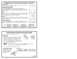
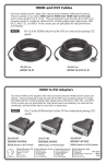
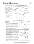
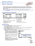
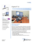
IR 402 Remote Control Instruction Guide
IR 402 Remote Control Instruction Guide, cont’d
Y/C
H
V
VID
C
IR/SERIAL OUT
PROJ CONT
Y
C
B
A
RS-232
Tx Rx G Ps G +V
S G S G S G
L
2
1
R
L
R
L
3
CM/IR/SCP
2
D
A B C D E
S G
+V G CM IR SCP
R
L
4
R
LAN
RELAYS
A
B
C
C 1
2 C 3
4 C 5
L LINEOUT R
CONFIG/RS-232
R
6
L PREAMP R
RIGHT
_
LEFT
_
4/8 ohm
B
AMPLIFIED
OUT
Y/C
G
AUDIO
V
R
OUTPUT
INPUT 3
H
INPUT 4
INPUT 2
B/C
VID
SCP 226
IR Link
OFF
VOLUME
PIC
MUTE
MUTE
AUTO
IMAGE
VCR
DVD
1
4
2
5
3
6
DOC
CAM
LAPTOP
PC
SIGNAL
IR
CONFIG
SCP 226
40
40
IR 402 Remote
INPUT 2
VID
R
Y/C
H
G
V
B
Y
VID
C
IR/SERIAL OUT
PROJ CONT
C
B
A
RS-232
Tx Rx G Ps G +V
S G S G S G
L
2
1
R
L
50-60Hz
R
L
3
CM/IR/SCP
2
D
A B C D E
S G
+V G CM IR SCP
R
L
4
R
RELAYS
A
B
C
C 1
2 C 3
4 C 5
L LINEOUT R
R
RIGHT
N Only the input switching and volume control work
without being set up with Global Configurator software. Control setup operations cannot be performed directly from the IR 402.
_
LEFT
_
SCP 226
System 5 IP Rear Panel
IR Link
OFF
VOLUME
PIC
MUTE
MUTE
AUTO
IMAGE
VCR
Extron Electronics, Europe
Beeldschermweg 6C
3821 AH Amersfoort, The Netherlands
+800.3987.6673 +31.33.453.4040
FAX +31.33.453.4050
Extron Electronics, Asia
135 Joo Seng Rd. #04-01
PM Industrial Bldg., Singapore 368363
+800.7339.8766 +65.6383.4400
FAX +65.6383.4664
Extron Electronics, Japan 11 07
Kyodo Building, 16 Ichibancho
Chiyoda-ku, Tokyo 102-0082
Japan
+81.3.3511.7655 FAX +81.3.3511.7656
When used with the Extron System 5 IP or an Extron MediaLink™ Controller (MLC 226 IP,
MLC 104 IP Plus), the IR 402 can be used for input selection and for audio, display, and
source control.
N The IR 402 does not work with the MLC 206 MediaLink Controller.
DISPLAY
ON
Front
Panel
Extron Electronics, USA
1230 South Lewis Street
Anaheim, CA 92805
800.633.9876 714.491.1500
FAX 714.491.1517
IR 402 Remote Control Instruction Guide
CONFIG/RS-232
6
L PREAMP R
4/8 ohm
Y/C
AMPLIFIED
OUT
VID
AUDIO
V
OUTPUT
V
H
C
B/C
+
H
INPUT 3
B/C
Y
G/Y
+
R/VID
INPUT 4
G/Y
INPUT 1
R/VID
IR 402
Remote
68-825-01 Rev. B
IR 402 Remote Control Instruction Guide, cont’d
LAN
• an IR Link connected to a System 5 IP, MLC 226 IP, or
MLC 104 IP Plus.
Via the control software, you can define what functions and/or
actions occur at the press of each button.
www.extron.com
1.3A
• a System 5 IP or MLC 226 IP via the front panel IR pickup device.
• an SCP 226 via a connected System 5 IP or MLC 226 IP.
Refer to the System 5 IP, MLC 226 IP, or MLC 104 IP Plus user’s
manual and the Global Configurator help file for more information.
100-240V
DVD
1
4
2
5
3
6
DOC
CAM
LAPTOP
PC
SIGNAL
IR
CONFIG
SCP 226
IR LINK
Operation
• a System 5 IP or MLC 226 IP via the front panel IR pickup device.
The buttons on the Extron IR 402 duplicate the power, volume, source selection, and function
controls on a System 5 IP or MLC front panel. The switcher or MLC responds to IR 402 button
presses as if the corresponding button or knob were pressed or turned at the switcher or
controller.
• an IR Link connected to a System 5 IP, MLC 226 IP, or
MLC 104 IP Plus.
N The buttons on the IR 402 cannot be used to set up the switcher or controller.
From a distance of no more than 30 feet (9.1 m) and
within 40° of the axis, the IR 402 sends infrared (IR) signals to
• an SCP 226 via a connected System 5 IP or MLC 226 IP.
Via the control software, you can define what functions and/or
actions occur at the press of each button.
IR 402
Remote
N Only the input switching and volume control work
without being set up with Global Configurator software. Control setup operations cannot be performed directly from the IR 402.
68-825-01 Rev. B
Extron Electronics, USA
1230 South Lewis Street
Anaheim, CA 92805
800.633.9876 714.491.1500
FAX 714.491.1517
Extron Electronics, Europe
Beeldschermweg 6C
3821 AH Amersfoort, The Netherlands
+800.3987.6673 +31.33.453.4040
FAX +31.33.453.4050
IR LINK
From a distance of no more than 30 feet (9.1 m) and
within 40° of the axis, the IR 402 sends infrared (IR) signals to
30 feet
max.
Install two AAA batteries as shown at right.
www.extron.com
G/Y
VID
ON
The VCR and DVD control, function, display mute, and audio mute buttons can be used with
or without any optional control modules. In order for these buttons to work, you must run
the Global Configurator software and configure the buttons, programming each of them
with commands. If not configured, those buttons do not function.
IR 402 Remote
V
Front
Panel
N The buttons on the IR 402 cannot be used to set up the switcher or controller.
30 feet
max.
H
C
DISPLAY
The buttons on the Extron IR 402 duplicate the power, volume, source selection, and function
controls on a System 5 IP or MLC front panel. The switcher or MLC responds to IR 402 button
presses as if the corresponding button or knob were pressed or turned at the switcher or
controller.
40
B/C
Y
System 5 IP Rear Panel
CONFIG
Operation
40
G/Y
+
R/VID
N The IR 402 does not work with the MLC 206 MediaLink Controller.
CONFIG
R/VID
50-60Hz
IR
IR
1.3A
INPUT 1
100-240V
+
When used with the Extron System 5 IP or an Extron MediaLink™ Controller (MLC 226 IP,
MLC 104 IP Plus), the IR 402 can be used for input selection and for audio, display, and
source control.
Extron Electronics, Asia
135 Joo Seng Rd. #04-01
PM Industrial Bldg., Singapore 368363
+800.7339.8766 +65.6383.4400
FAX +65.6383.4664
Extron Electronics, Japan 11 07
Kyodo Building, 16 Ichibancho
Chiyoda-ku, Tokyo 102-0082
Japan
+81.3.3511.7655 FAX +81.3.3511.7656
The VCR and DVD control, function, display mute, and audio mute buttons can be used with
or without any optional control modules. In order for these buttons to work, you must run
the Global Configurator software and configure the buttons, programming each of them
with commands. If not configured, those buttons do not function.
Install two AAA batteries as shown at right.
Refer to the System 5 IP, MLC 226 IP, or MLC 104 IP Plus user’s
manual and the Global Configurator help file for more information.