1
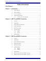
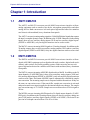
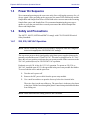
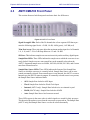
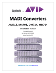
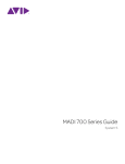
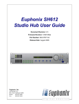
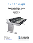
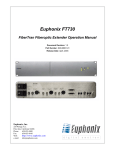
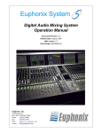
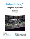
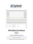
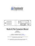
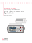
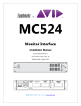
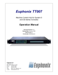
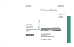
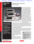
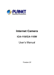
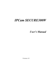
Euphonix MADI Converters Manual
AM713 Analog to MADI, MA703 MADI to Analog
DM714 Digital to MADI, MD704 MADI to Digital
Document Revision: 2.1
Release Date: May, 2005
Part Number: 840-08416-02
Euphonix Inc.
220 Portage Ave.
Palo Alto, California 94306
Phone:
650-855-0400
Fax:
650-855-0410
Web:
http://www.euphonix.com
e-mail:
[email protected]
In the interest of continued product development, Euphonix Inc. reserves the right to make
improvements in this manual and the products it describes at any time, without notice or
obligation.
System 5, S5, Max Air, PatchNet, eMix, EuCon, R-1, Audio Deck, Studio Hub are trademarks
of Euphonix, Inc.
©2002 Euphonix, Inc. All rights reserved worldwide. No part of this publication may be
reproduced, transmitted, transcribed, stored in a retrieval system, or translated into any
language in any form by any means without written permission from Euphonix, Inc.
Euphonix MADI Converters Operation Manual
Table of Contents
List of Figures ....................................................................................................................... vi
Chapter 1: Introduction ...................................................................................................7
1.1
AM713/MA703 .........................................................................................7
1.2
DM714/MD704 .........................................................................................7
1.3
Power On Sequence...................................................................................8
1.4
Safety and Precautions ..............................................................................8
1.4.1
220, 230, 240 VAC Operation ....................................................8
Chapter 2: AM713 and MA703 Converters ..........................................................11
2.1
Features....................................................................................................11
2.2
Applications.............................................................................................11
2.3
AM713/MA703 Front Panel....................................................................12
2.4
AM713 Rear Panel ..................................................................................14
2.5
MA703 Rear Panel ..................................................................................16
2.6
Synchronization.......................................................................................18
2.6.1
2.6.2
2.7
AM713 ......................................................................................18
MA703 ......................................................................................18
Specifications ..........................................................................................19
Chapter 3: DM714 and MD704 Converters ..........................................................23
3.1
Features....................................................................................................23
3.2
Applications.............................................................................................23
3.3
DM 714/MD704 Front Panel...................................................................24
3.4
DM714 Rear Panel ..................................................................................26
3.5
MD704 Rear Panel ..................................................................................28
3.6
Synchronization.......................................................................................30
3.6.1
3.6.2
DM714 ......................................................................................30
MD704 ......................................................................................30
3.7
Specifications ..........................................................................................31
3.8
DM714: Pinout for Female DB25 Connector .........................................34
3.9
MD704: Pinout for Female DB25 Connector .........................................35
v
Euphonix MADI Converters Operation Manual
List of Figures
2-1
AM713 Front Panel ..........................................................................................................12
2-2
AM713 Rear Panel ............................................................................................................14
2-3
MA703 Rear Panel ............................................................................................................16
3-1
DM714 Front Panel ..........................................................................................................24
3-2
DM714 Rear Panel ............................................................................................................26
3-3
MD704 Rear Panel ............................................................................................................28
3-4
DM714 Female DB25 Connector .....................................................................................34
3-5
MD704 Female DB25 Connector .....................................................................................35
vi
Euphonix MADI Converters Operation Manual
Chapter 1: Introduction
1.1
AM713/MA703
The AM713 and MA703 converters provide MADI conversion to interface to/from
analog equipment such as consoles, tape decks, microphone preamplifiers and other
analog devices. Both converters are two rack spaces high and are housed in a stainless
steel chassis with machined, heavy aluminum front panels.
The AM713 converts incoming analog signals to 24-bit MADI digital signals that capture
the input’s complete dynamic range. In addition to the 24 XLR connectors for the analog
inputs, there are two auxiliary analog inputs (XLR) and two auxiliary digital inputs
(S/PDIF or AES/EBU); only one digital connector can be used at a time.
The MA703 converts incoming MADI signals to 24 analog channels. In addition to the
24 analog outputs, there are also two auxiliary analog outputs (XLR) and two auxiliary
digital outputs (S/PDIF or AES/EBU). Only one digital connector can be used at a time.
1.2
DM714/MD704
The DM714 and MD704 converters provide MADI conversion to interface to/from
digital (AES/EBU) equipment such as digital multi-track recorders, digital audio workstations, audio routers, and facility patching systems. Both converters are two rack
spaces high and are housed in a stainless steel chassis with machined, heavy aluminum
front panels.
The DM714 converts incoming AES/EBU digital audio to MADI. In addition to the 24
input channels (12 AES/EBU pairs), there are two auxiliary analog inputs (XLR) and
two auxiliary digital inputs (S/PDIF or AES/EBU); only one auxiliary digital connector
can be used at a time. Each main AES/EBU input is automatically evaluated for samplerate conversion. The incoming sample rate is compared with the internal rate. If they are
the same, no conversion occurs. If the rates differ, sample-rate conversion is activated
and persists until a new input is applied or the internal sample rate changes. The samplerate conversion range is 32–56 kHz. Sample-rate conversion reduces a 24-bit signal to
20 bits.
The MD704 converts incoming MADI signals to 24 digital output channels (12 AES/
EBU pairs). In addition to the 24 analog outputs, there are also two auxiliary analog outputs (XLR) and two auxiliary digital outputs (S/PDIF or AES/EBU). The main 24 outputs can be bit-depth converted from 24 to 20 or 16 bits.
5
Euphonix MADI Converters Operation Manual
1.3
Introduction
Power On Sequence
We recommend powering up the converters only after verifying the presence of a valid sync signal. After powering up the converters, the meter LEDs flash briefly and the
Sample Rate and Sample Rate Source LEDs blink as the converter senses the incoming
Sample Rate source and Sample Rate. We recommend monitoring the power-up sequence to verify the converters have correctly auto-sensed the desired Sample Rate
Source and Sample Rate.
1.4
Safety and Precautions
The AM713, MA703, MD704 and DM714 comply with CE’s EN 60950 Electrical
Safety Standards.
1.4.1
220, 230, 240 VAC Operation
NOTE: Before connecting power to the converters, change the fuse and voltage selector to the appropriate 220/230/240 VAC settings.
The converters preserve their signal quality using linear power supplies that must be
manually switched between 115 and 230 VAC. The units are shipped set for 115 VAC.
Move the red, two-position switch near the power entry module of the converters to the
230 VAC position (down) for 220/230/240 VAC operation.
Each unit uses a 0.630 A fuse for 115 VAC operation. To operate at 220, 230, or
240 VAC, install the spare 0.315 A fuse provided in the power entry module fuse-holder.
To access both the active and the spare fuse:
1.
Turn the unit’s power off.
2.
Remove the IEC power cable from the power entry module.
3.
Use a small screwdriver to open the fuse tray below the electrical inlet.
The active fuse is to the rear of the tray. The spare fuse is in the tray slot closest
to the front. Pull the fuses through the plastic constriction point that holds them
from falling out.
NOTE: Never disconnect the safety ground to the converters.
6
Euphonix MADI Converters Operation Manual
Introduction
Power Cord Requirements
The converters are supplied with North American IEC power cords. If this cord is
changed to allow a different plug configuration, it is the responsibility of the user to select an approved power cord with proper construction material, current capacity, flexibility, and strength characteristics.
Cooling
We strongly recommend providing adequate ventilation to the converters, particularly
when installed in a rack. The AM713 and MA703 converters in particular should have
space left above and below every two units so heat can properly dissipate.
7
Euphonix MADI Converters Operation Manual
Introduction
8
Euphonix MADI Converters Operation Manual
Chapter 2: AM713 and MA703 Converters
2.1
Features
Professional grade audio conversion is accomplished utilizing 128 times over-sampled noise-shaped delta-sigma techniques. The analog to digital conversion employs a multi-bit modular architecture while the digital to analog conversion
employs a single-bit modulator architecture. Low-jitter reference clocks are provided utilizing digital PLL techniques with VCXO and VCO oscillators.
The analog inputs and outputs can be calibrated from the front panel of each unit. Four
segment LEDs on the front panel monitor signal level. LED meter segments indicate
-42, -18, -6 (green) and -0.005 dBFS (red).
AES/EBU and Word Clock external sync inputs on both units provide synchronization to digital systems. Sample Rate Source and Sample Rate are automatically sensed
by both units. Supported sample rates include 44.1, 48, 88.2, and 96 kHz. In addition,
pull-up and pull-down rates for the standard sample rates, as well as custom sample
rates are available.
2.2
Applications
In addition to their standard use in a Euphonix digital system, the AM713 and MA703
can be used as stand-alone converters when 24, 48, or more channels of analog-toMADI and/or MADI-to-analog conversion is necessary (i.e., interfacing an analog tape
deck to a digital mixer). When used with the Euphonix SH612 Studio Hub, this is a
powerful conversion and MADI routing system that can be used to interface between
an analog console and an otherwise all-digital facility (i.e., TV broadcast facility).
NOTE: MADI cables can be extended to 50 m (164 ft), allowing remote location of the
converters.
9
Euphonix MADI Converters Operation Manual
2.3
AM713 and MA703 Converters
AM713/MA703 Front Panel
This section discusses both front panels and notes their few differences.
Figure 2-1 AM713 Front Panel
Signal Strength LEDs: Each of the 28 channels has a four-segment LED that represents the following signal levels: -42 dB, -18 dB, -6 dB (green), -0.05 dB (red).
Trim Pots Access: Three trim pots adjust the maximum analog input level of channels
1–8, 9–16, and 17–24 in 2-dB steps between +12 and +26 dBu.
SR Conv: This indicates sample-rate conversion activity on the auxiliary digital inputs.
Sample Rate LEDs: These LEDs indicate the sample rate to which the converter is currently locked. Sample rates are auto-sensed but can be manually selected on the
AM713. Supported sample rates are 96 kHz, 88.2 kHz, 48 kHz, 44.1 kHz, and Custom
rates from external sources.
Sample Rate Source LEDs: These LEDs indicate the format of the Sample Rate
Source to which the converter is currently locked. Sample Rate Source can be autosensed or manually selected. If an external source is not detected, the AM713 reverts to
Internal sync; the MA703 mutes its outputs. If a manually selected source is not present,
the Sample Rate Source indicator blinks.
•
AES: Sample Rate locked to AES Input.
•
Word: Sample Rate locked to Word Clock Input.
•
Internal (AM713 only): Sample Rate locked to its own internal crystal.
•
MADI (MA703 only): Sample Rate locked to MADI.
•
Auto: Sample Rate Source has been auto-sensed.
These LEDs appear in the same order in which signals are tested for their presence.
This detection procedure occurs when the converters are powered on. The Sample Rate
(AM713 only) and Sample Rate Source can also be selected manually.
10
Euphonix MADI Converters Operation Manual
AM713 and MA703 Converters
Manual Selection Buttons: The button below each Sample Rate LED row manually
selects the sample rate. The AM713 also allows manual selection of the Sample Rate
Source.
Power Switch: On/Off switch.
NOTE: There are no user-serviceable parts in the converters.
11
Euphonix MADI Converters Operation Manual
2.4
AM713 and MA703 Converters
AM713 Rear Panel
Figure 2-2 AM713 Rear Panel
Input Voltage Selector: This red switch allows the unit to operate in either 110/115
VAC or 220/230/240 VAC environments. A fuse must also be changed for 220/230/240
VAC operation (see page 6). Units are shipped set and fused for 110/115 VAC.
Power Connector (IEC) and Fuse Tray: The IEC power connector accepts standard
IEC power cords. The fuse tray contains both the active fuse and a spare fuse for 220/
230/240 VAC operation. See page 6 for instructions on how to change the fuse for 220/
230/240 VAC operation.
Analog Inputs (female XLR): 24 balanced, analog inputs on XLR connectors. Input
sensitivity is set from the front panel.
Auxiliary Analog Inputs (female XLR): Two balanced analog inputs on XLR connectors.
Input sensitivity is set from the front panel.
AES/EBU Digital Input (female XLR): Stereo AES/EBU digital input on one XLR
connector. Functions in parallel with the auxiliary S/PDIF input and the two inputs
should not be used simultaneously.
S/PDIF Digital Input (RCA): Stereo S/PDIF digital input on one RCA connector.
Functions in parallel with the auxiliary AES/EBU input and the two inputs should not
be used simultaneously.
AES Sync In (female XLR): Master clock input for the converter when using AES as
Sample Rate Source.
AES Sync Thru (male XLR): Outputs the same signal connected to AES Sync In.
Word In (BNC): Master clock input for the converter when using Word Clock as
Sample Rate Source.
Word Out (BNC): Outputs a Word clock signal synchronized to the Sample Rate
Source. In the presence of an external Word clock input, this connector provides a
regenerated version of that input signal. Without an external sample rate source, this
connector outputs the internally generated clock signal.
12
Euphonix MADI Converters Operation Manual
AM713 and MA703 Converters
MADI Out (BNC): Outputs the digital audio signal.
•
1–24:
Analog inputs
•
25–26: Aux analog inputs
•
27–28: Aux digital inputs
NOTE: 28 channels are always transmitted; dual channels are not used.
13
Euphonix MADI Converters Operation Manual
2.5
AM713 and MA703 Converters
MA703 Rear Panel
Figure 2-3 MA703 Rear Panel
Input Voltage Selector: This red switch sets the unit to either 110/115 VAC or 220/
230/240 VAC environments. A fuse must also be changed for 220/230/240 VAC operation (see page 6). Units are shipped set and fused for 110/115 VAC.
Power Connector (IEC) and Fuse Tray: The IEC power connector accepts standard
IEC power cords. The fuse tray contains both the active and spare fuses. See page 6 to
learn how to change the fuse for 220/230/240 VAC operation.
Analog Outputs (male XLR): 24 balanced analog outputs on XLR connectors. Output
level is set from the front panel.
Auxiliary Analog Outputs (male XLR): Two balanced analog outputs on XLR connectors. Output level can is set from the front panel.
AES/EBU Digital Outputs (male XLR): Stereo AES/EBU digital outputs on one XLR
connector. Functions in parallel with the auxiliary S/PDIF output and the two inputs
should not be used simultaneously.
S/PDIF Digital Outputs (RCA): Stereo S/PDIF digital output on one RCA connector.
Functions in parallel with the auxiliary AES/EBU output and the two inputs should not
be used simultaneously.
AES Sync In (female XLR): Master clock input for the converter when using AES as
the Sample Rate Source.
AES Sync Thru (male XLR): Outputs the same signal connected to AES Sync In.
Word In (BNC): Master clock input for the converter when using Word Clock as
Sample Rate Source.
Word Out (BNC): Outputs a Word Clock signal synchronized to the Sample Rate
Source. In the presence of an external Word clock input, this connector provides a
regenerated version of the input signal. Without an external sample rate source, this
connector outputs an internally generated clock signal.
14
Euphonix MADI Converters Operation Manual
AM713 and MA703 Converters
MADI In (BNC): Digital audio signal input.
•
1–24:
analog outputs
•
25–26: aux analog outputs
•
27–28: aux digital outputs
15
Euphonix MADI Converters Operation Manual
2.6
Synchronization
2.6.1
AM713
AM713 and MA703 Converters
The AM713’s Sample Rate is set externally by one of two source signals or internally
by crystals and associated circuitry. The Sample Rate Source is determined automatically by the presence of signals when the AM713 is powered on. The order in which
external signals are tested for presence is: AES, Word, Internal.
The detected signal immediately becomes the source for the AM713’s sample rate
clock. The auto-sensed Sample Rate Source can be overridden using the button on the
front panel of the AM713, below the Sample Rate Source LEDs. If neither AES nor
Word Clock signals are present, the AM713 uses its internal clock driven by crystals.
The default internal Sample Rate of the AM713 is 48 kHz. This default internal rate can
be overridden with the Sample Rate button on the front panel of the AM713 (directly
below the Sample Rate LEDs) to 44.1, 48 or 96 kHz.
2.6.2
MA703
The MA703 detects Sample Rate and Sample Rate Source like the AM713 with the
following differences:
•
Since the MA703 is always a slave to an external Sample Rate Source, there is
no internal Sample Rate Source setting.
•
The MA703 can use MADI in addition to AES or Word Clock as a Sample Rate
Source, and detects the presence of these signals in the following order: AES,
Word, MADI.
When a signal is detected, it immediately becomes the sample rate clock of the MA703.
The auto-sensed Sample Rate Source can be overridden with the Sample Rate Source
button on the front panel of the MA703, below the Sample Rate Source LEDs.
16
Euphonix MADI Converters Operation Manual
2.7
AM713 and MA703 Converters
Specifications
AM713 Performance Specifications
Sync Sources
AES, word clock, internal
Sync Outputs
AES thru and word clock out
Sync Detection
Auto or switched
Internal Sample Rate
44.1, 48, 88.2, 96 kHz ±50 ppm
Lock range
fine mode
custom mode
Audio Inputs
±300 ppm
±12% varispeed of 44.1 and 48 kHz
Above 50 kHz, varispeed can adjust the nominal sample rate by -12 to +5%
24 analog, 4 aux channels (2 analog, 2 digital)
Main Inputs (1–24)
Electronically balanced XLR; 20 kΩ input impedance
Level for 0 dBFS
Signal-to-Noise Ratio
THD
Frequency Response
(1 kHz @ +4 dBu)
CMRR
Crosstalk
Group Delay
Adjustable between +12 and +26 dBu in 2-dB steps
105 dB (unweighted)
0.0005%
±0.25 dB 20 Hz – 20 kHz @ 48 kHz
-2.5 dB 20 Hz – 40 kHz @ 96 kHz
>50 dB 20 Hz – 20 kHz
≥ -110 dB @ 1 kHz
≥ -100dB 20 Hz – 20 kHz
41.7/Fs (869 µs @ 48 kHz)
Aux Digital Inputs (D1/2)
AES (XLR), transformer isolated, 110 Ω
S/PDIF (RCA), 75 Ω
Aux Analog Inputs (A1/2)
same as main inputs
MADI Output
BNC 75 Ω
28 channels at all sample rates
Inputs mapped to channels 1–24, A1/2 to 25/26, D1/2 to 27/28
24-bit signal path
17
MA703 Performance Specifications
Sync Sources
AES, word clock, MADI
Sync Outputs
AES thru and word clock out
Sync Detection
Auto or switched
Internal Sample Rate
44.1, 48, 88.2, 96 kHz ±50 ppm
Lock range
fine mode
custom mode
±300 ppm
±12% varispeed of 44.1 and 48 kHz
Above 50 kHz, varispeed can adjust the nominal sample rate by -12 to +5%
MADI Input
BNC 75 Ω
44.1/48 kHz: 56 channels
88.2/96 kHz: 28 channels. Outputs mapped to channels 1–24, A1/2 to 25/26,
D1/2 to 27/28. 24-bit signal path
Audio Outputs
24 analog, 4 aux channels (2 analog, 2 digital)
Main Outputs (1–24)
Electronically balanced XLR; 200 Ω output impedance
Level for 0 dBFS
Signal-to-Noise Ratio
THD
Frequency Response
(1 kHz @ +4 dBu)
CMRR
Crosstalk
Group Delay
Aux Digital Outputs (D1/2)
Digital Format
Aux Analog Outputs (A1/2)
Adjustable between +12 and +26 dBu in 2-dB steps
101 dB (unweighted)
0.0003%
±0.25 dB 20 Hz – 20 kHz @ 48 kHz
-2.5 dB 20 Hz – 40 kHz @ 96 kHz
>50 dB 20 Hz – 20 kHz
≥ -110 dB @ 1 kHz
≥ -100 dB 20 Hz – 20 kHz
28.2/Fs (588 µs @ 48 kHz)
AES (XLR), transformer isolated, 110 Ω
S/PDIF (RCA), 75 Ω
professional or consumer (internally switched)
same as main outputs
Euphonix MADI Converters Operation Manual
AM713 and MA703 Converters
AM713/MA703 Technical Specifications
Power Requirements
110/115 VAC or 220/230/240 VAC; 50 or 60 Hz
Power Consumption
50 W
Temperature of Operation
5–35°C
Dimensions
Height: 3.5 in; Width: 19 in; Depth: 18.25 in; Weight: 17 lb
19
Euphonix MADI Converters Operation Manual
AM713 and MA703 Converters
20
Euphonix MADI Converters Operation Manual
Chapter 3: DM714 and MD704 Converters
3.1
Features
AES/EBU and Word Clock external sync inputs on both units provide synchronization to
digital systems. Sample Rate Source and Sample Rate are automatically sensed by both
units. Supported sample rates include 44.1, 48, 88.2, and 96 kHz. In addition, pull-up
and pull-down rates for the standard sample rates, as well as custom sample rates are
available.
Four-segment front panel LEDs monitor the input/output signal strength. LED meter
segments indicate -42, -18, -6 (green) and -0.005 dBFS (red).
The analog inputs and outputs can be calibrated from the front panel of each unit.
3.2
Applications
The DM714 and MD704 can be used as 24-channel digital interfaces in a Euphonix
digital system or other situations requiring digital to MADI conversion. These devices
allow recording or transferring to/from digital devices that are not compatible with
MADI but have an AES/EBU interface.
NOTE: MADI cables can be extended to 50 m (164 ft), allowing remote location of the
converters.
21
Euphonix MADI Converters Operation Manual
3.3
DM714 and MD704 Converters
DM 714/MD704 Front Panel
This section discusses both front panels and notes their few differences.
Figure 3-1 DM714 Front Panel
Signal Strength LEDs: Each of the 28 channels has a four-segment LED that represents the following signal levels: -42 dB, -18 dB, -6 dB (green), -.05 dB (red).
Trim Pot: A trim pot adjusts the analog output level of channels A1 and A2 between
+12 and +26 dBu in 2-dB steps.
SR Conv: The sample rate of all digital inputs is automatically detected and, if asynchronous, converted to the system Sample Rate. This process is independently applied
to each stereo pair such that a combination of synchronous and asynchronous signals
can be connected to the DM714. Sample-rate conversion is switched off when synchronous signals are detected. The range of sample-rate conversion is 32–56 kHz. 88.2 or
96 kHz signals cannot be sample-rate converted and are passed through if synchronous.
If non-synchronous 88.2 or 96 kHz signals are detected, the upper signal strength LED
flashes red to warn the user that the sample rate for those channels is not in sync with
the system settings. Sample-rate conversion reduces the bit depth in a 24-bit signal to
20 bits.
Sample Rate LEDs: These LEDs indicate the Sample Rate to which the converter is
currently locked. Sample Rates are auto-sensed but can be manually selected on the
DM714. Supported Sample Rates are 96 kHz, 88.2 kHz, 48 kHz, 44.1 kHz and Custom
Rates from external sources.
Sample Rate Source LEDs: These LEDs indicate the format of the Sample Rate
Source to which the converter is currently locked. Sample Rate Source can be autosensed or manually selected. If an external source is not detected, the DM714 reverts to
Internal sync; the MD704 mutes its outputs. If a manually selected source is not present,
the Sample Rate Source indicator blinks.
22
Euphonix MADI Converters Operation Manual
DM714 and MD704 Converters
•
AES: Sample Rate locked to AES Input.
•
Word: Sample Rate locked to Word Clock Input.
•
Internal (DM714 only): Sample Rate locked to its own internal crystal.
•
MADI (MD704 only): Sample Rate locked to MADI.
•
Auto: Sample Rate Source has been auto-sensed.
These LEDs appear in the same order in which signals are tested for presence. This
detection procedure occurs when the converters are powered on. The Sample Rate
(DM714 only) and Sample Rate Source can also be selected manually.
Manual Selection Buttons: The button below each Sample Rate LED row manually
selects the Sample Rate Source. The DM714 also allows manual selection of the
Sample Rate.
Power Switch: On/Off switch.
NOTE: There are no user-serviceable parts in the converters.
23
Euphonix MADI Converters Operation Manual
3.4
DM714 and MD704 Converters
DM714 Rear Panel
Figure 3-2 DM714 Rear Panel
Input Voltage Selector: This red switch allows the unit to operate in either 110/
115 VAC or 220/230/240 VAC environments. A fuse must also be changed for 220/
230/240 VAC operation (see page 6). Units are shipped set and fused for 110/115 VAC.
Power Connector (IEC) and Fuse Tray: The IEC power connector accepts standard
IEC power cords. The fuse tray contains both the active fuse and a spare fuse for 220/
230/240 VAC operation. See page 6 for instructions on how to change the fuse for 220/
230/240 VAC operation.
AES/EBU Digital Inputs (female XLR): 12 AES/EBU stereo inputs.
Parallel AES/EBU Digital Inputs (female DB25): Three 8-channel digital connectors
function in parallel with XLR digital inputs, and should not be used simultaneously
with the XLR inputs. See Figure 3-4 on page 32 for pinout diagram.
Auxiliary Analog Inputs (female XLR): Two balanced analog inputs on XLR connectors. Input sensitivity is set from the front panel.
Auxiliary AES/EBU Digital Input (female XLR): Stereo AES/EBU digital input on
one XLR connector. Functions in parallel with the auxiliary S/PDIF input and the two
inputs should not be used simultaneously.
Auxiliary S/PDIF Digital Input (RCA): Stereo S/PDIF digital input on one RCA connector. Functions in parallel with the auxiliary AES/EBU input and the two inputs
should not be used simultaneously.
AES Sync In (female XLR): Master clock input for the converter when using AES as
Sample Rate Source.
AES Sync Thru (male XLR): Outputs the same signal connected to AES Sync In.
Word In (BNC): Master clock input for the converter when using Word Clock as
Sample Rate Source.
24
Euphonix MADI Converters Operation Manual
DM714 and MD704 Converters
Word Out (BNC): Outputs a Word clock signal synchronized to the Sample Rate
Source. In the presence of an external Word clock input, this connector provides a regenerated version of that input signal. Without an external sample rate source, this connector outputs the internally generated clock signal.
MADI Out (BNC): Outputs the digital audio signal.
•
1–24: Main digital inputs
•
25–26: Aux analog inputs
•
27–28: Aux digital inputs
NOTE: 28 channels are always transmitted; dual channels are not used.
25
Euphonix MADI Converters Operation Manual
3.5
DM714 and MD704 Converters
MD704 Rear Panel
Figure 3-3 MD704 Rear Panel
Input Voltage Selector: This red switch sets the unit to either 110/115 VAC or 220/
230/240 VAC environments. A fuse must also be changed for 220/230/240 VAC operation (see page 6). Units are shipped set and fused for 110/115 VAC.
Power Connector (IEC) and Fuse Tray: The IEC power connector accepts standard
IEC power cords. The fuse tray contains both the active and spare fuses. See page 6 to
learn how to change the fuse for 220/230/240 VAC operation.
AES/EBU Digital Outputs (female XLR): 12 AES/EBU stereo outputs.
Parallel AES/EBU Digital Outputs (female DB25): Three 8-channel digital connectors
function in parallel with XLR digital outputs and the two outputs should not be used
simultaneously. See Figure 3-5 on page 33 for pinout diagram.
Auxiliary Analog Outputs (male XLR): Two balanced analog outputs on XLR connectors. Output level can is set from the front panel.
AES/EBU Digital Outputs (male XLR): Stereo AES/EBU digital outputs on one XLR
connector. Functions in parallel with the auxiliary S/PDIF output and the two outputs
should not be used simultaneously.
S/PDIF Digital Outputs (RCA): Stereo S/PDIF digital output on one RCA connector.
Functions in parallel with the auxiliary AES/EBU output and the two outputs should
not be used simultaneously.
AES Sync In (female XLR): Master clock input for the converter when using AES as
the Sample Rate Source.
AES Sync Thru (male XLR): Outputs the same signal connected to AES Sync In.
Word In (BNC): Master clock input for the converter when using Word Clock as
Sample Rate Source.
Word Out (BNC): Outputs a Word Clock signal synchronized to the Sample Rate
Source. In the presence of an external Word clock input, this connector provides a regenerated version of the input signal. Without an external sample rate source, this
connector outputs an internally generated clock signal.
26
Euphonix MADI Converters Operation Manual
DM714 and MD704 Converters
MADI In (BNC): Digital audio signal input.
•
1–24:
main digital outputs
•
25–26: aux analog outputs
•
27–28: aux digital outputs
Bit-Depth Reduction: Sets the resolution to 16, 20, or 24 bits for the main AES/EBU
channels.
27
Euphonix MADI Converters Operation Manual
3.6
Synchronization
3.6.1
DM714
DM714 and MD704 Converters
The DM714’s Sample Rate is set externally by one of two source signals or internally
by crystals and associated circuitry. The Sample Rate Source is determined automatically by the presence of signals when the DM714 is powered on. The order in which
external signals are tested for presence is: AES, Word, Internal.
The detected signal immediately becomes the source for the DM714’s sample rate
clock. The auto-sensed Sample Rate Source can be overridden using the button on the
front panel of the DM714, below the Sample Rate Source LEDs. If neither AES nor
Word Clock signals are present, the DM714 uses its internal clock derived from onboard voltage-controlled crystal.
The default internal Sample Rate of the DM714 is 48 kHz. This default internal rate can
be overridden with the Sample Rate button on the front panel of the DM714 (directly
below the Sample Rate LEDs) to 44.1, 48 or 96 kHz.
3.6.2
MD704
The MD704 detects Sample Rate and Sample Rate Source like the DM714 with the
following two differences:
•
Since the MD704 is always a slave to an external Sample Rate Source, there is
no internal Sample Rate setting.
•
The MD704 can use MADI in addition to AES or Word Clock as a Sample Rate
Source, and detects the presence of these signals in the following order: AES,
Word, MADI.
When a signal is detected, it immediately becomes the sample rate clock of the MD704.
The auto-sensed Sample Rate Source can be overridden with the Sample Rate Source
button on the front panel of the MD704, below the Sample Rate Source LEDs.
NOTE: The converters occasionally do not lock to a 96 kHz AES Sync signal. This
condition can normally be remedied by cycling the converter’s power, disconnecting and reconnecting the AES Sync signal, or using Word Clock.
28
Euphonix MADI Converters Operation Manual
3.7
DM714 and MD704 Converters
Specifications
DM714 Performance Specifications
Sync Sources
AES, word clock, internal
Sync Outputs
AES thru and word clock out
Sync Detection
Auto or switched
Internal Sample Rate
44.1, 48, 88.2, 96 kHz ±50 ppm
Lock range
fine mode
custom mode
Audio Inputs
±300 ppm
±12% varispeed of 44.1 and 48 kHz
24 analog, 4 aux channels (2 analog, 2 digital)
Main Inputs (1–24)
XLR, transformer isolated, 110 Ω, 24-bit
Sample-rate conversion automatically applied to non-synchronous 44.1 or 48
kHz inputs with reduction to 20 bits (88.2 or 96 kHz not yet supported).
Group delay varies with sync frequency and inputs
Aux Digital Inputs (D1/2)
AES (XLR), transformer isolated, 110 Ω
S/PDIF (RCA), 75 Ω
Aux Analog Inputs (A1/2)
Electronically balanced XLR; 20 kΩ input impedance
Level for 0 dBFS
Signal-to-Noise Ratio
THD
Frequency Response
(1 kHz @ +4 dBu)
CMRR
Crosstalk
Group Delay
Adjustable between +12 and +26 dBu, in 2-dB steps
105 dB (unweighted)
0.0005%
±0.5 dB 20 Hz – 20 kHz @ 48 kHz
-2.5 dB 20 Hz – 40 kHz @ 96 kHz
>50 dB 20 Hz – 20 kHz
> -110 dB @ 1 kHz; > -100 dB 20 Hz – 20 kHz
41.7/Fs (869 ms @ 48 kHz)
MADI Output
BNC 75 Ω
28 channels at all sample rates
Inputs mapped to channels 1–24, A1/2 to 25/26, D1/2 to 27/28
24-bit signal path
Sample-Rate Conversion
Automatic detection and conversion of asynchronous sample rates on digital
inputs. SRC automatically switched off for synchronous channels.
SRC Range
32–56 kHz
29
Euphonix MADI Converters Operation Manual
DM714 and MD704 Converters
MD704 Performance Specifications
Sync Sources
AES, word clock, internal
Sync Outputs
AES thru and word clock out
Sync Detection
Auto or switched
Internal Sample Rate
44.1, 48, 88.2, 96 kHz ±50 ppm
Lock range
fine mode
custom mode
±300 ppm
±12% varispeed of 44.1 and 48 kHz
MADI Input
BNC 75 Ω
28 channels at all sample rates
Outputs mapped to channels 1–24, A1/2 to 25/26, D1/2 to 27/28
24-bit signal path
Audio Outputs
24 analog, 4 aux channels (2 analog, 2 digital)
Main Outputs (1–24)
AES on XLR, transformer isolated, 110 Ω, 24 bit
User can truncate to 16- or 20-bit per stereo pair
Truncation Type
Dither Type
Digital Format
Group Delay
Aux Digital Outputs (D1/2)
Digital Format
Aux Analog Outputs (A1/2)
Level for 0 dBFS
Signal-to-Noise Ratio
THD
Frequency Response
(1 kHz @ +4 dBu)
Crosstalk
Group Delay
Dithered or 1st order noise-shaped, internally switched
TPDF (active only for 16- or 20-bit word length)
Pro or Consumer, internally switched
3/Fs (63 ms @ 48 kHz)
AES (XLR), transformer isolated, 110 Ω
S/PDIF (RCA), 75 Ω
professional or consumer (internally switched)
Electronically balanced XLR; 20 kΩ input impedance
Adjustable between +12 and +26 dBu in 2-dB steps
101 dB (unweighted)
0.0003%
±0.5 dB 20 Hz – 20 kHz @ 48 kHz
-2.5 dB 20 Hz – 40 kHz @ 96 kHz
> -110 dB @ 1 kHz; > -100dB 20 Hz – 20 kHz
28.2/Fs (588 µs@ 48 kHz)
30
Euphonix MADI Converters Operation Manual
DM714 and MD704 Converters
AM713/MA703 Technical Specifications
Power Requirements
110/115 VAC or 220/230/240 VAC; 50 or 60 Hz
Power Consumption
25 W
Temperature of Operation
5–35°C
Dimensions
Height: 3.5 in; Width: 19 in; Depth: 18.25 in; Weight: 17 lb
31
Euphonix MADI Converters Operation Manual
3.8
DM714 and MD704 Converters
DM714: Pinout for Female DB25 Connector
13
1
25
14
Figure 3-4 DM714 Female DB25 Connector
Table 3-1 DM714 DB25 Pinout
Pin Number
Signal
1–6
no connect
7
Digital in 7/8 + (or 15/16, 23/24 +)
8
GND
9
Digital in 5/6 - (or 13/14, 21/22 -)
10
Digital in 3/4 + (or 11/12, 19/20 +)
11
GND
12
Digital in 1/2 - (or 9/10, 17/18 -)
13–19
no connect
20
Digital in 7/8 - (or 15/16, 23/24 +)
21
Digital in 5/6 + (or 13/14, 21/22 +)
22
GND
23
Digital in 3/4 - (or 11/12, 19/20 -)
24
Digital in 1/2 + (or 9/10, 17/18 +)
25
GND
NOTE: The same pinout applies to the female DB25 connectors for channels 9–16
and 17–24.
32
Euphonix MADI Converters Operation Manual
3.9
DM714 and MD704 Converters
MD704: Pinout for Female DB25 Connector
13
1
25
14
Figure 3-5 MD704 Female DB25 Connector
Table 3-2 MD704 DB25 Pinout
Pin
Number
Signal
1
Digital out 7/8 + (or 15/16, 23/24 +)
2
GND
3
Digital out 5/6 - (or 13/14, 21/22 -)
4
Digital out 3/4 + (or 11/12, 19/20 +)
5
GND
6
Digital out 1/2 - (or 9/10, 17/18 -)
7–13
no connect
14
Digital out 7/8 - (or 15/16, 23/24 -)
15
Digital out 5/6 + (or 13/14, 21/22 +)
16
GND
17
Digital out 3/4 - (or 11/12, 19/20 -)
18
Digital out 1/2 + (or 9/10, 17/18 +)
19
GND
20–25
no connect
NOTE: The same pinout applies to the female DB25 connectors for channels 9–16
and 17–24.
33
Euphonix MADI Converters Operation Manual
DM714 and MD704 Converters
34