1
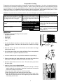
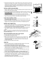
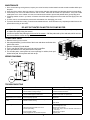
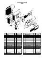
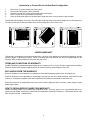
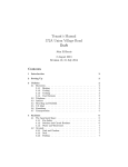
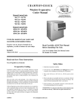
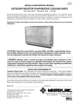
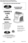
OWNER’S MANUAL
WINDOW EVAPORATIVE AIR COOLER
MODEL: N30W
READ AND SAVE THIS INSTRUCTION MANUAL
Date Purchased: _______________________________
Purchased From: _______________________________
P/N 70852
REV. 4/09
Evaporative Cooling
Evaporative cooling uses the principle of evaporation to lower the air temperature. Hot, dry air is passed through wetted filters and is converted to refreshingly cooled air. Essick Coolers make the best use of the evaporative process
by controlling the flow of water, spreading the water evenly over the filters, and keeping a steady stream of cooled air
entering your home. It is exhausted out open windows or doors, carrying heat, smoke and odors along with it. Essick
evaporative coolers are up to 80% less costly to operate than refrigerated air conditioners.
Cautions: To prevent harm to yourself and others, and to avoid damage to your cooler, PLEASE follow these guidelines.
When Installing
When Operating
When Servicing
Make sure that unit is installed on a sound Make sure that circuit cooler is plugged Always Unplug the cooler before attemptstructure that will support the full operat- into is equipped with a (slow blow) breaker ing service of any kind.
ing weight of the cooler. See page 4.
large enough to support the full amperage
of the cooler
Before attempting to hang the cooler in To reduce the risk of fire or electrical Be sure to disconnect nit from power
the window, remove the louver to reduce shock, DO NOT use this fan with any source before servicing. If not, it can be
weight.
Solid-state speed control device.
turned on from inside the house and start
unexpectedly.
Do Not connect power to cooler before in- This cooler is equipped with an automatic
thermally protected motor. If it shuts off
stallation is complete.
on its own for any reason, it can restart
without warning.
If the motor shuts off because of thermal
overload, check into the problem immediately. If allowed to continue, permanent
damage will occur.
MOUNTING
To install this cooler, the following tools are required:
• Adjustable wrenches
• Screwdrivers
• Electric drill
• 3/16” drill bit
• Level
1. Cut the Side Sealer Channels so that two of them will span the window
when butted together. Place two of the channels on the bottom duct flange
as shown.
Side Sealer
Channel
2. Place the cooler in the center of the window with the bottom duct flange
resting against the sill.
3. Pull out the Spacer-Rods so as to allow the Rubber Feet to rest against the
side of the house. Tighten the Adjustment Screws.
4. Lower the window to rest on top of the duct behind the top duct flange.
5. Fasten a stop above the inside window sash to prevent the window from
being raised. Raising the window may cause the cooler to fall.
6. Adjust the Spacer-Rods to level the cooler. This will ensure proper water
flow to the pads.
7. Install the Chain Supports (Not Included).
a. Drill pilot holes in the window frame, 3 feet above the top of the duct
and the width of the cooler apart. Install the Screw-Hooks in these pilot
holes to the full depth of the thread.
b. Hook one end of each Chain over each Screw-Hook.
c. Place S-Hooks in the holes at the top rear of the cooler.
d. Place the opposite end of the S-Hooks in the free end of each Chain.
Make sure the chains are taut, but not so tight they pull the bottom of the
cooler away from the wall.
2
SCREW
HOOK
CHAIN
S-HOOK
8. Install the Side Sealer Panels. These panels are the correct height, but need to be
trimmed to fit the width of our window. Trim the panels so that they reach from the
window frame to the side of the duct. Slide the panels in the channels you placed on
the bottom duct flange. Install the remaining Side-Sealer Channels over the top duct
flange and the Side-Sealer Panels.
INSTALL OVERFLOW AND DRAIN
1. Slide the Rubber Washer over the Drain Bushing and push through the hole in the
bottom of the cooler from the top side.
2. Secure the Drain Bushing from beneath the pan with the Lock Nut. Make sure the
Rubber Washer does not twist while tightening, which could cause it to leak. NO
NOT OVERTIGHTEN.
3. Thread the Overflow Tube into the Drain Bushing and HAND TIGHTEN.
4. If leakage occurs after Reservoir is full retighten the Overflow Pipe until leaking
stops. A small amount of silicone caulk may be used if necessary.
Side Sealer
Side Sealer Channel
Overflow
Tube
FLOAT VALVE INSTALLATION
1. Place the threaded portion of the Float Valve through the hole provided in the
Float Bracket (inside unit) as shown.
2. Slip the Fiber Washer over the threaded portion of the float and secure with the
Ring Nut. Be sure the Float does not turn while you are tightening the nut.
Bushing
Rubber
Gasket
WATER LINE CONNECTION
1. Find the closest outside water faucet, and install a Water Connection Kit (not
included with cooler) as shown. If an exterior faucet is not available, locate the
closest cold water pipe and install a saddle valve assembly.
2. Route tubing into cooler. Place Compression Nut and Ferrule over end of tubing. Insert the tubing into float valve and tighten Compression Nut to
secure.
NOTE: Over tightening a compression fitting will cause that fitting to leak.
It is best to secure the connections, turn on the water, and then snug the
fitting until leaking stops.
Lock
Nut
Reservoir
Compression
Nut
Ferrule
Ring Nut
Fiber Washer
Float
ADJUSTING WATER LEVEL AND FLOAT VALVE
1. To adjust water level, bend the float valve rod.
2. Check all water connections for leaks.
3. Make sure the Float Valve cuts off completely when the desired water
level has been reached (1/2” to 3/4” below top of Overflow Tube). If the
float does not stop the water completely, the water level will rise and run
out the Overflow Tube.
4. Double check the Overflow Tube for leaks.
Ferrule
Compression
Nut
START UP
1. Plug in the electrical cord to a standard grounded receptacle. Be sure the
circuit breaker protecting the receptacle is of sufficient size.
2. Open windows in rooms where you want cooling to be directed.
3. Turn the cooler to the High Fan position. Observe the amount of air being
delivered. Note: On cool nights (or days) or when the humidity level is high,
the fan positions may be used for ventilation purposes.
4. Turn the cooler to the Low Fan position. This should significantly reduce the
amount of air being delivered.
5. Turn the cooler to the Pump Only position. The pump should run and not
the fan. Check to see that water is flowing from all three Water Trays.
6. Turn the cooler to the High Cool position. Check to see that all three Pads
are wetting evenly with no dry patches. The Pads may take up to 20 minutes to wet fully. If the Pads have dry patches, you can adjust the level of
each Water Tray by screws on each end.
7. Adjust window openings to achieve desired cooling level.
3
Faucet
Sillcock
Water Supply
Valve
MAINTENANCE
1. Once a month during cooling season, inspect your cooler for leaks, blocked water lines and excessive residue build-up on
the pads.
2. At the end of the season, drain the reservoir. Remove the drainpipe and let water and dirt pass through the drain fitting.
3. Lime build-up can occur in the water reservoir and on louvers. Clean this off at least once per season. If any rust or bare
metal spots occur on the cabinet or louver, the metal should be sanded, primed and painted with a good quality paint.
4. If freezing weather occurs in your area, it is best to shut off the water supply at the source and drain the supply line to the
cooler.
5. A cooler cover is recommended to prevent rain and weather from damaging your cooler.
6. To prevent the Shaft from rusting, coat with a wax based lubricant. Allow lubricant to dry completely and all fumes to disperse before turning on the cooler.
DO NOT GET WATER ON MOTOR OR PUMP MOTOR
NOTE: Depending on the mineral content of the water or the amount of air borne dust in your are, you may need
to replace filter pads during the season.
It is best to replace filter pads again at the end of the season. Old filter pads soak up lime and salts, which can rust
the louvers and the cabinet during the winter months.
TO REPLACE PADS
1. Remove louver (U) from cooler.
2. Unhook pad holders (V) at the sides of the louver and above and below side
pads inside cooler.
3. Remove old pads (W) and discard.
4. Tuck in rear pad to make sure hot air can not by-pass filter.
5. Place pad holders over new pad and hook into place.
6. For the side pads, center pad over louver openings in cabinet, hook pad
holder below pad, tilt into place and hook at top.
WIRING DIAGRAM
TROUBLESHOOTING
Problem
Cause
Remedy
Motor cycles on and off
• Extension cord (if one used) too long
• Circuit breaker not large enough
• Choose a shorter or heavier gauge cord
• Consult a licensed electrician
Fails to start
• No electrical power
• Circuit breaker tripped or fuse blown
• Check all electrical connections and cords
• Reset circuit breaker or replace fuse
Water draining from overflow
• Float improperly adjusted
• Adjust float
Blower vibrates excessively or
rattles
• Blower wheel out of balance or out of alignment
• Debris in blower housing
• Replace the blower wheel
Not cooling
• Blocked water lines
• Clear debris
• Windows opened too little or too much.
• Uneven pad wetting
• Pump clogged or failed
• Pads plugged with dirt and water deposits
4
• Check incoming water line, float and water distributor
for blockages and clear.
• Adjust window openings
• Level water trays, check for blocked water slots in
water trays
• Clean pump or replace
• Replace pads
REPLACEMENT PARTS
N30W
Item
Qty
Part No.
Item
Qty
Part No.
1
Cabinet
Description
1
322160-001
19
Water Distributor
Description
1
3D-30
2
Blower
1
70866
20
Pump Assembly
1
70569
3
Duct
1
322120-001
21
Pump Bracket
1
504281
4
Side Sealer
2
110603
22
Water Hose
1
70276
5
Louver
1
224007-007
23
Switch
1
110425
6
Water Tray - Back
1
226003-002
24
Knob
1
110839-006
7
Water Tray - Side
2
226004-001
25
Side Sealer Channel
4
110599
8
Filter - Back
1
110098
26
Float Valve
1
FL-C
9
Filter - Side
2
110084
27
Water Overflow Kit
1
3OA-1
10
Pad Retainer - Back
2
3PW-5
28
Sub-Vent Assembly
1
310839-103
11
Pad Retainer - Side
2
70415
29
Louver Assembly
1
324007-107
12
Motor
1
110441-2
30
Inlet Ring
1
224120-004
13
Blower Wheel
1
110764
31
Float Bracket
1
70373
14
Motor Mount Bushing
4
110731
32
Switch Bracket
1
70798
15
Motor Mount
2
218109-001
33
Grill Frame
1
110839
16
Stand-off Bracket
2
70417
34
Cord
1
70414
17
Stand-Off Rod
2
110811
35
Top
1
222160-007
18
Rubber Foot
2
110706
36
Switch Box
1
524342
5
Instructions to Convert Unit to Vertical Duct Configuration
1.
2.
3.
4.
5.
Remove the 13 screws holding the Duct in place.
Turn the Duct 90 degrees counter-clockwise.
Align the Duct with the 3 holes provided above the blower panel.
Insert 3 screws at the top and bottom of the duct.
Place the Duct Mount Strip over the side Duct Flange and insert 3 screws into the holes provided.
Proceed with the installation as normal. The side Sealer Channels will go on the same flanges as for a horizontal duct.
You may use the Side Sealers provided to close off the window above your cooler’s duct.
LIMITED WARRANTY
This warranty is extended to the original purchaser only. It does not cover damages incurred during shipping or through
accident, neglect, or abuse by the owner. Essick Air Products does not authorize any person or representative to assume any other or different liability in connection with this cooler.
TERMS AND CONDITIONS OF WARRANTY
The BOTTOM PAN is guaranteed against leakage due to rusting out for Five Years. All other original parts provided by
Essick Air Products are warranted against defects in material or factory workmanship for One Year.
EXCLUSIONS FROM THE WARRANTY
Essick Air Products is not responsible for incidental or consequential damage resulting from any malfunction.
Essick Air Products is not responsible for any damage occurring from the use of water softeners, chemicals, de-scale
material, or if a higher horsepower motor than what Essick Air Products recommends is used in the unit.
Essick Air Products is not responsible for the cost of service calls to diagnose cause of trouble, or labor charge to repair
and/or replace parts.
HOW TO OBTAIN SERVICE UNDER THIS WARRANTY
Contact the Dealer where you purchased the evaporative cooler. If for any reason you are not satisfied with the response from the Dealer, contact the Customer Service Department: Essick Air Products Inc., 5800 Murray Street, Little
Rock, Arkansas 72209. 1-800-643-8341.
6