1
Confidential
Developer's Guide
SR-600
Issued date
,
,
Issued by
EPSON
English
401333300
Confidential
Developer's Guide SR-600
Confidential
Table of contents
Revision Information . . . . . . . . . . . . . . . . . . . . . . . . . . . . . . . . . . . . . . . . . . . . . . . . . . . . iv
Warnings, Cautions, and Notes . . . . . . . . . . . . . . . . . . . . . . . . . . . . . . . . . . . . . . . . . . . iv
Guide Configuration . . . . . . . . . . . . . . . . . . . . . . . . . . . . . . . . . . . . . . . . . . . . . . . . . . . viii
Chapter 1
General Features
Features of the product . . . . . . . . . . . . . . . . . . . . . . . . . . . . . . . . . . . . . . . . . . . . . . . . . 1-1
Part Names . . . . . . . . . . . . . . . . . . . . . . . . . . . . . . . . . . . . . . . . . . . . . . . . . . . . . . . . . . . 1-5
Required Clearance . . . . . . . . . . . . . . . . . . . . . . . . . . . . . . . . . . . . . . . . . . . . . . . . . . . 1-11
Chapter 2
OS and Driver Setup
Supporting OS . . . . . . . . . . . . . . . . . . . . . . . . . . . . . . . . . . . . . . . . . . . . . . . . . . . . . . . . . 2-1
MS-DOS . . . . . . . . . . . . . . . . . . . . . . . . . . . . . . . . . . . . . . . . . . . . . . . . . . . . . . . . . . . . . . 2-1
Windows 95 . . . . . . . . . . . . . . . . . . . . . . . . . . . . . . . . . . . . . . . . . . . . . . . . . . . . . . . . . . . 2-4
Windows 98 . . . . . . . . . . . . . . . . . . . . . . . . . . . . . . . . . . . . . . . . . . . . . . . . . . . . . . . . . . . 2-9
Windows NT 4.0 . . . . . . . . . . . . . . . . . . . . . . . . . . . . . . . . . . . . . . . . . . . . . . . . . . . . . . 2-13
Windows2000 . . . . . . . . . . . . . . . . . . . . . . . . . . . . . . . . . . . . . . . . . . . . . . . . . . . . . . . . 2-20
Chapter 3
BIOS Setup
BIOS Setup Utility . . . . . . . . . . . . . . . . . . . . . . . . . . . . . . . . . . . . . . . . . . . . . . . . . . . . . 3-1
Power On Self Test (POST) . . . . . . . . . . . . . . . . . . . . . . . . . . . . . . . . . . . . . . . . . . . . . 3-11
Device Diagnostics Utility . . . . . . . . . . . . . . . . . . . . . . . . . . . . . . . . . . . . . . . . . . . . . . 3-15
Chapter 4
Driver / Utility Specifications
Network Driver . . . . . . . . . . . . . . . . . . . . . . . . . . . . . . . . . . . . . . . . . . . . . . . . . . . . . . . . 4-3
Video Driver . . . . . . . . . . . . . . . . . . . . . . . . . . . . . . . . . . . . . . . . . . . . . . . . . . . . . . . . . . 4-4
Log on (Software Keyboard) Utility . . . . . . . . . . . . . . . . . . . . . . . . . . . . . . . . . . . . . . 4-5
Screen Saver (For NT) . . . . . . . . . . . . . . . . . . . . . . . . . . . . . . . . . . . . . . . . . . . . . . . . . . 4-7
EPSON OPOS ADK . . . . . . . . . . . . . . . . . . . . . . . . . . . . . . . . . . . . . . . . . . . . . . . . . . . 4-11
Chapter 5
Hardware Specifications
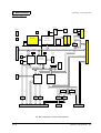
Circuit Board Functions . . . . . . . . . . . . . . . . . . . . . . . . . . . . . . . . . . . . . . . . . . . . . . . . . 5-1
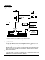
System . . . . . . . . . . . . . . . . . . . . . . . . . . . . . . . . . . . . . . . . . . . . . . . . . . . . . . . . . . . . . . . 5-2
Mother Board . . . . . . . . . . . . . . . . . . . . . . . . . . . . . . . . . . . . . . . . . . . . . . . . . . . . . . . . . 5-7
Power Supply Unit . . . . . . . . . . . . . . . . . . . . . . . . . . . . . . . . . . . . . . . . . . . . . . . . . . . . 5-11
Multi Video Mode . . . . . . . . . . . . . . . . . . . . . . . . . . . . . . . . . . . . . . . . . . . . . . . . . . . . 5-14
PCI Board . . . . . . . . . . . . . . . . . . . . . . . . . . . . . . . . . . . . . . . . . . . . . . . . . . . . . . . . . . . . 5-15
Power Supply Unit . . . . . . . . . . . . . . . . . . . . . . . . . . . . . . . . . . . . . . . . . . . . . . . . . . . . 5-16
FDD . . . . . . . . . . . . . . . . . . . . . . . . . . . . . . . . . . . . . . . . . . . . . . . . . . . . . . . . . . . . . . . . . 5-18
HDD . . . . . . . . . . . . . . . . . . . . . . . . . . . . . . . . . . . . . . . . . . . . . . . . . . . . . . . . . . . . . . . . 5-18
CD-ROM Drive(Optional) . . . . . . . . . . . . . . . . . . . . . . . . . . . . . . . . . . . . . . . . . . . . . . 5-19
CompactFlash Card(Optional or Specified Product) . . . . . . . . . . . . . . . . . . . . . . . 5-19
LCD/Keyboard unit . . . . . . . . . . . . . . . . . . . . . . . . . . . . . . . . . . . . . . . . . . . . . . . . . . 5-20
Chapter 6
Peripherals/Option Installation
LCD Unit . . . . . . . . . . . . . . . . . . . . . . . . . . . . . . . . . . . . . . . . . . . . . . . . . . . . . . . . . . . . . 6-2
CD-ROM Drive . . . . . . . . . . . . . . . . . . . . . . . . . . . . . . . . . . . . . . . . . . . . . . . . . . . . . . . 6-14
Drawer /CRT Board . . . . . . . . . . . . . . . . . . . . . . . . . . . . . . . . . . . . . . . . . . . . . . . . . . 6-17
Compact Flash Slot . . . . . . . . . . . . . . . . . . . . . . . . . . . . . . . . . . . . . . . . . . . . . . . . . . . . 6-23
MSR Unit . . . . . . . . . . . . . . . . . . . . . . . . . . . . . . . . . . . . . . . . . . . . . . . . . . . . . . . . . . . . 6-27
DM-D Unit . . . . . . . . . . . . . . . . . . . . . . . . . . . . . . . . . . . . . . . . . . . . . . . . . . . . . . . . . . . 6-44
Floppy Disk Drive . . . . . . . . . . . . . . . . . . . . . . . . . . . . . . . . . . . . . . . . . . . . . . . . . . . . 6-45
DIMM . . . . . . . . . . . . . . . . . . . . . . . . . . . . . . . . . . . . . . . . . . . . . . . . . . . . . . . . . . . . . . . 6-46
Rev.A
i
Confidential
Appendix 1 Interfaces
Connector Location . . . . . . . . . . . . . . . . . . . . . . . . . . . . . . . . . . . . . . . . . . . Appendix 1-1
Serial Port . . . . . . . . . . . . . . . . . . . . . . . . . . . . . . . . . . . . . . . . . . . . . . . . . . . Appendix 1-2
Parallel Port (LPT Port) . . . . . . . . . . . . . . . . . . . . . . . . . . . . . . . . . . . . . . . Appendix 1-3
Keyboard/Mouse Port . . . . . . . . . . . . . . . . . . . . . . . . . . . . . . . . . . . . . . . . Appendix 1-4
USB Port . . . . . . . . . . . . . . . . . . . . . . . . . . . . . . . . . . . . . . . . . . . . . . . . . . . . Appendix 1-5
Ethernet Port . . . . . . . . . . . . . . . . . . . . . . . . . . . . . . . . . . . . . . . . . . . . . . . . Appendix 1-6
Customer Display Port . . . . . . . . . . . . . . . . . . . . . . . . . . . . . . . . . . . . . . . . Appendix 1-7
CRT Port . . . . . . . . . . . . . . . . . . . . . . . . . . . . . . . . . . . . . . . . . . . . . . . . . . . . Appendix 1-8
Drawer Port . . . . . . . . . . . . . . . . . . . . . . . . . . . . . . . . . . . . . . . . . . . . . . . . . Appendix 1-9
Floppy Disk Drive Connector . . . . . . . . . . . . . . . . . . . . . . . . . . . . . . . . . Appendix 1-10
PCI Slot . . . . . . . . . . . . . . . . . . . . . . . . . . . . . . . . . . . . . . . . . . . . . . . . . . . . Appendix 1-11
Appendix 2
Power Management
Description . . . . . . . . . . . . . . . . . . . . . . . . . . . . . . . . . . . . . . . . . . . . . . . . . . Appendix 2-1
Suspend . . . . . . . . . . . . . . . . . . . . . . . . . . . . . . . . . . . . . . . . . . . . . . . . . . . . Appendix 2-3
Video Off . . . . . . . . . . . . . . . . . . . . . . . . . . . . . . . . . . . . . . . . . . . . . . . . . . . Appendix 2-6
Front Power Switch Function . . . . . . . . . . . . . . . . . . . . . . . . . . . . . . . . . . Appendix 2-8
Recommended Setting according with Operation . . . . . . . . . . . . . . . . Appendix 2-12
Restrictions . . . . . . . . . . . . . . . . . . . . . . . . . . . . . . . . . . . . . . . . . . . . . . . . . Appendix 2-12
Appendix 3
Wake On LAN
Descriptions . . . . . . . . . . . . . . . . . . . . . . . . . . . . . . . . . . . . . . . . . . . . . . . . . Appendix 3-1
Software Setting . . . . . . . . . . . . . . . . . . . . . . . . . . . . . . . . . . . . . . . . . . . . . . Appendix 3-3
Function Details . . . . . . . . . . . . . . . . . . . . . . . . . . . . . . . . . . . . . . . . . . . . . . Appendix 3-5
Appendix 4
COM3 Mode
Description . . . . . . . . . . . . . . . . . . . . . . . . . . . . . . . . . . . . . . . . . . . . . . . . . . Appendix 4-1
COM3 Mode Seting Specification . . . . . . . . . . . . . . . . . . . . . . . . . . . . . . . Appendix 4-2
INDEX . . . . . . . . . . . . . . . . . . . . . . . . . . . . . . . . . . . . . . . . . . . . . . . . . . . . . . . . . . . .Index-1
ii
Rev.A
Developer's Guide SR-600
Confidential
CONFIDENTIALITY AGREEMENT
BY USING THIS DOCUMENT, YOU AGREE TO ABIDE BY THE TERMS OF THIS AGREEMENT. PLEASE
RETURN THIS DOCUMENT IMMEDIATELY IF YOU DO NOT AGREE TO THESE TERMS.
❏
This document contains confidential, proprietary information of Seiko Epson Corporation or its affiliates. You
must keep such information confidential. If the user is a business entity or organization, you must limit disclosure
to your employees, agents, and contractors who have a need to know and who are also bound by obligations of
confidentiality.
❏
On the earlier of (a) termination of your relationship with Seiko Epson, or (b) Seiko Epson’s request, you must
stop using the confidential information. You must then return or destroy the information, as directed by Seiko
Epson.
❏
If a court, arbitrator, government agency, or the like orders you to disclose any confidential information, you
mustimmediately notify Seiko Epson. You agree to give Seiko Epson reasonable cooperation and assistance in
resisting disclosure.
❏
You may use confidential information only for the purpose of facilitating authorized sales and service of, or
developing software and similar products for authorized use with, the products to which the document relates,
unless you obtain the prior written consent of Seiko Epson for some other use.
❏
Seiko Epson warrants that it has the right to disclose the confidential information. SEIKO EPSON MAKES NO
OTHER WARRANTIES CONCERNING THE CONFIDENTIAL INFORMATION OR ANY OTHER
INFORMATION IN THE DOCUMENT, INCLUDING (WITHOUT LIMITATION) ANY WARRANTY OF TITLE
OR NON-INFRINGEMENT. Seiko Epson has no liability for loss or damage arising from or relating to your use of
or reliance on the information in the document.
❏
You may not reproduce, store, or transmit the confidential information in any form or by any means (electronic,
mechanical, photocopying, recording, or otherwise) without the prior written permission of Seiko Epson.
❏
Your obligations under this Agreement are in addition to any other legal obligations. Seiko Epson does not waive
any right under this Agreement by failing to exercise it. The laws of Japan apply to this Agreement.
CAUTIONS
❏
This document shall apply only to the product(s) identified herein.
❏
No part of this document may be reproduced, stored in a retrieval system, or transmitted in any form or by any
means, electronic, mechanical, photocopying, recording, or otherwise, without the prior written permission of
Seiko Epson Corporation.
❏
The contents of this document are subject to change without notice. Please contact us for the latest information.
❏
While every precaution has been taken in the preparation of this document, Seiko Epson Corporation assumes no
responsibility for errors or omissions.
❏
Neither is any liability assumed for damages resulting from the use of the information contained herein.
❏
Neither Seiko Epson Corporation nor its affiliates shall be liable to the purchaser of this product or third parties
for damages, losses, costs, or expenses incurred by the purchaser or third parties as a result of: accident, misuse, or
abuse of this product or unauthorized modifications, repairs, or alterations to this product, or (excluding the U.S.)
failure to strictly comply with Seiko Epson Corporation's operating and maintenance instructions.
❏
Seiko Epson Corporation shall not be liable against any damages or problems arising from the use of any options
or any consumable products other than those designated as Original EPSON Products or EPSON Approved
Products by Seiko Epson Corporation.
TRADEMARKS
EPSON ® is a registered trademark of Seiko Epson Corporation.
General Notice: Other product and company names used herein are for identification purposes only and may be
trademarks of their respective companies.
Rev.A
iii
Confidential
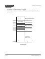
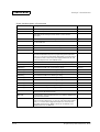
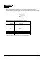
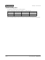
Revision Information
Revision
Page
Altered Item and Contents
Rev. A
Warnings, Cautions, and Notes
Notes and precautions in this manual are identified as defined below.
WARNING:
Provides information that must be followed carefully to avoid bodily injury.
CAUTION:
Provides information that must be observed to prevent damage to the equipment or
loss of data.
❏ Possibility of sustaining physical injuries.
❏ Possibility of causing physical damages.
❏ Possibility of causing information loss.
Note:
Provides important information and useful tips on handling the equipment.
iv
Rev.A
Confidential
Developer's Guide SR-600
Safety Precautions
This section presents important information intended to ensure safe and effective use of this
product. Please read this section carefully and store it in an accessible location.
WARNING:
❏ Turn off the main power switch immediately and unplug the power cord if the SR-600
produces smoke, a strange odor, or unusual noise. Continued use may lead to fire or
electric shock. Contact your dealer or an EPSON service center for advice.
❏ Never attempt to repair this product yourself. Improper repair work can be
dangerous.
❏ Never disassemble or modify this product. Tampering with this product may result in
injury, fire, or electric shock.
❏ Be sure to use the specified power supply. Using an unsuitable power supply may
cause fire or electric shock.
❏ Never insert or disconnect the power plug with wet hands. Doing so may result in
severe shock.
❏ Do not allow foreign objects to fall into this product. Penetration by foreign objects
may lead to fire or shock.
❏ Do not plug too many leads into a single socket. It may lead to fire.
❏ Handle the power cord with care. Improper handling may lead to fire or shock.
❏ Do not modify or attempt to repair the cord.
Rev.A
•
Do not process the power cord.
•
Do not place any object on top of the cord.
•
Avoid excessive bending, twisting, and pulling.
•
Do not place the cord near heating equipment.
•
Check that the plug is clean before plugging it in.
•
Be sure to push the prongs all the way in.
v
Confidential
CAUTION:
❏ Be sure your power cable meets the relevant safety standards and includes a
power-system ground terminal (PE terminal). Improper interconnections may lead to
crash or fire.
❏ Be sure to set this product on a firm, stable and horizontal surface. The product may
break or cause injury if it falls.
❏ Do not use in locations subject to high humidity or dust levels. Excessive humidity and
dust may cause equipment damage, fire, or shock.
❏ Do not place multiple loads on the power outlet (wall outlet). Overloading the outlet
may lead to fire.
❏ To ensure safety, unplug this product prior to leaving it unused for an extended
period.
Note:
❏ Be sure to use the EPSON supplied DIMM, HDD and CPU.
❏ To get the lastest information about which Compact Flash and PCI board can be used with
this product, contact your EPSON dealer.
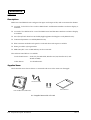
Note for Maintenance, Repair, and Inspection
WARNING:
❏ Wear a ground wristlet to prevent the system failure from the static electricity during
the handling of the internal circuit board.
❏ If you remove the internal circuit board, place the circuit board on the antistatic
rubber surface or equivalent product to prevent the system failure from the static
electricity.
❏ Handle the power cord with care, improper handling may lead to fire.
❏ Do not modify or attempt to repair the cord.
❏ Do not operate the maintenance, repairing or inspection to avoid the electric shock
when it’s thunderstorming.
❏ It is possible that the temperature of the circuit board device is high. Besure to wait
for about 10 minutes after turned off the power to handle the circuit board device.
❏ Do not give the circuit board impacts or vibrations. It may result in the system failure.
❏ Do not touch the circuit board or cable terminals. It may cause the system failure
from the dirt.
vi
Rev.A
Confidential
Developer's Guide SR-600
❏ Never clean the product with thinner, benzene, alcohol or other such solvent. It may
result in deformation or breakage of the plastic and rubber made supplies of this
product.
❏ Clean this product with dry or wettish fabric. Be sure to unplug the power cord
before clean this product.
Note for Deacquisition
Note:
Follow the country(or local) law and the regulation for the disposal of this product.
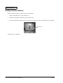
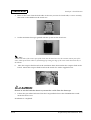
Modular Type Connector
Be careful not to cut your finger on any edge of he unit.The Caution label as shown below is
sticked around the three modular type connector on the rear and bottom sides of this product.
CAUTION:
The modular type connector is used as a dedicated connector for cash drawer or customer
display. Do not connect it with the public circuits, Network, or LAN. It does not operate as an
Ethernet Connector.
Rev.A
vii
Confidential
Guide Configuration
Aim of the Manual
This manual was created to provide information on the SR-600 for anyone who is developing
programs, and setting upthe optional supplies and the printer.
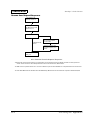
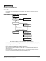
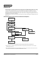
Contents of the Manual
The configurations of this manual is summarized in the table below.
Chapter 1 “General Features"
Gives descriptions of SR-600 and the parts
names.
Chapter 2 “OS and Driver Setup”
Gives descriptions of the OS and the Driver
compliant with each OS.
Chapter 3 “BIOS Setup”
Gives descriptions of the BIOS, POST, and the
Device Diagnostic Utility.
Chapter 4 “Driver / Utility
Specifications”
Gives specifications for the Drivers and
Utilities.
Chapter 5 “Hardware Specifications”
Gives specifications for the Hardware
configurations and the optional supplies.
Chapter 6 “Peripherals/Option
Installation”
Gives specifications for the optional peripherals
and setup.
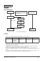
Appendix 1 “Interfaces”
Gives specifications for all the interfaces.
Appendix 2 “Power Management”
Gives specifications for the Power Management
Function.
Appendix 3 “Wake On LAN”
Gives specifications for the Wake On LAN
function.
Appendix 4 “COM3 Mode”
Gives descriptions of the COM3 Mode.
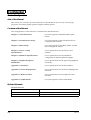
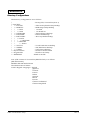
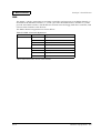
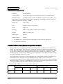
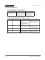
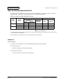
Related Manuals
Related Manuals
viii
Name
Contents
SR-600 User’s Manual
Gives basic handling guidelines of SR-600.
SR-600 Service Manual
Gives guidelines for anyone who supports and repairs SR-600.
Rev.A
Confidential
Developer's Guide SR-600
Chapter 1
General Features
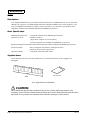
Features of the product
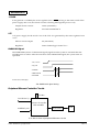
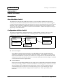
Hardware Configurations
The SR-600 is an intelligent terminal developed for the POS environment.
The SR-600 has the following features:
❏
A high speed Intel Celeron processor provides the power and speed necessary for data
processing.
❏ Using it with a variety of options and peripheral devices allows you to construct a system that
suits your needs best.
❏ Designed with a stylish color and shape, it is waterproof and easy to care for.
❏ The lock on the front cover allows only the key owner to take out a CD-ROM.
❏ The power management function supplies only the amount of power necessary for data
processing, assuring optimum power saving.
❏ Use of PC/AT compatible BIOS.
❏ Support of Plug & Play function. (Windows 98/2000 only)
❏ Wake up function can be available over a LAN.
❏ Use of design consistent with the EPSON POS system DM series Customer Display. A
customer display can be mounted on the SR-600, so it does not occupy much space.
❏ Two disk spaces are provided for HDD, CD-ROM, and/or CompactFlash.
❏ A 2.5-inch hard disk drive can be stored in hard disk drive.
❏ The PC-based open architecture with a PCI slot increases system expandability.
❏ Three serial ports, one parallel port, and two USB port allow connection of peripheral
devices, increasing system expandability.
❏ An Ethernet controller can be used to 100Base-TX or 10Base-T.
❏ A CompactFlash board can be installed.
❏ The built-in IBM PS 2 keyboard port supports IBM PC/AT compatible keyboards.
❏ A CD-ROM drive can be installed.
❏ LCD unit (option) is a 12.1-inch TFT with Touch Panel or can be selected from DSTN, which
allows you to make a free layout for the application screen.
❏ A 2MB video memory is internally equipped using a PCI video controller.
Rev.A
General Features 1-1
Confidential
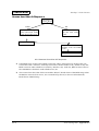
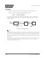
Software Configurations
BIOS setup
BIOS setup defines your system configuration. When you set up the product for the first time,
run this program to set the system environment. When you want to change the operating
environment, run this program again. For details on BIOS setup, refer to “Chapter 3, BIOS
Setup.”
Device self-diagnosis utility
Device self-diagnosis utility performs a test on each devices and functions of the SR-600. For
details on device self-diagnosis utility, refer to “Chapter 3, BIOS Setup.”
1-2 General Features
Rev.A
Confidential
Developer's Guide SR-600
Operating System
The SR-600 runs on the standard Microsoft ® operating systems:
Rev.A
•
Windows 95
•
Windows 98
•
Windows NT Workstation 4.0
•
MS-DOS 6.2
•
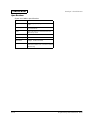
Windows 2000 Professional (It’ll be available in the near future.)
General Features 1-3
Confidential
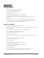
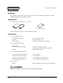
Peripheral Devices
The SR-600 can be configured with the following optional units:
❏ LCD units
12.1” color DSTN
12.1” color TFT
Model Name DM-LS121S
Model Name DM-LS121T
❏ MSR units
ISO I track 1,2,3
Model NameDM-MS123
❏ Floppy disk drive
3.5” 720KB/1.44MB
Model Name OI-S01
❏ CD-ROM drive
Model Name OI-S02
❏ Drawer board
Cash drawer x 2 port
CRT x 1 port
Model Name OI-B08
❏ CompactFlash board
For HDD attachment
For CD-ROM attachment
1-4 General Features
Model Name OI-S03-012
Model Name OI-S03-022
Rev.A
Confidential
Developer's Guide SR-600
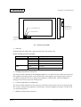
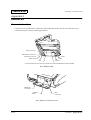
Part Names
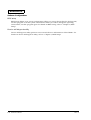
Front View
LCD Unit
Switch Cover
CD Cover
Key Lock
Front Power Switch
Reset Switch
Speaker Volume
K/B Mouse Connector
CD-ROM Access LED
CD-ROM Eject Button
CD-ROM Drive
FDD Connector
Figure 1-1 Front views of the SR-600
Rev.A
General Features 1-5
Confidential
DM-LS121S
Power LED
HDD LED
Contrast Adjustment
Switch
Figure 1-2 External views of the DM-LS121S
DM-LS121T
Power LED
HDD LED
Backlight Brightness
Adjustment Switch
Figure 1-3 External views of the DM-LS121T
1-6 General Features
Rev.A
Confidential
Developer's Guide SR-600
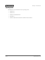
Rear View
MSR Unit
Connector
Rear Cover
Main Cover
Customer Display
Connector
Main Power Switch
Main Power Connector
Figure 1-4 Rear views of the SR-600
Rev.A
General Features 1-7
Confidential
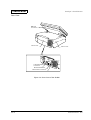
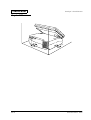
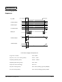
Bottom View
:
*CRT Connector
*Drawer Kick Connector
COM1
Ethernet Connector
USB Connector
COM2
LPT
COM3
Figure 1-5 Bottom views of the SR-600
* CRT and drawer kick connector is used if the optional CRT/drawer board is installed.
Ventilator
LCD Angle Adjusment
Lever
Figure 1-6 Side views of the SR-600
1-8 General Features
Rev.A
Confidential
Developer's Guide SR-600
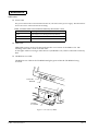
Switches
❏ Front power switch
The front power switch is a push type switch on the bottom of the left side corner under the
switch cover. It turns on and off the system. The front power switch is placed under the front
cover to prevent the operation mistake from being turning off accidentally. It changes the
front power status of SR-600 to power on, standby, or off. The functionality of the front
power switch is determined by BIOS Setup utiliy.
❏ Main power switch
The main power switch on the back of the SR-600 isolates the AC line voltage from the
power supply. Remove the rear cover to turn on and off the main power. During the normal
use, this switch is left on.
❏ Reset Switch
The reset switch under the switch cover by the right side of the front power switch resets the
hardware of the SR-600. If the system hangs for any reason and cannot recover, pressing this
switch restarts the system.
Reset Switch
Front Power
Switch
Main Power
Switch
Figure 1-7 Switch locations Rev.A
General Features 1-9
Confidential
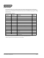
Indicators
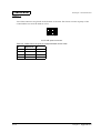
❏ Power LED
The power LED on the LCD unit indicates the on/off status of the power supply. The table below
shows the colors of the LED and its meaning.
Table 1-1 Power LED colors and their meaning shows the colors
LED color
Meaning when illuminated
Green
Power supply is on (during normal operations)
Orange
Power is suspended
Off
Power is off
❏ HDD LED
HDD LED (Green) on the LCD unit indicates the access status of the HDD or CF. The
meaning of the LED is same in all the units.
It also lights while accessing to other devices (CD-ROM or CF) which connected to Primary
IDE.
❏ CD-ROM Access LED
CD-ROM access LED on the CD-ROM unit lights green while the CD-ROM is being
accessed.
Power LED
HDD LED
CD-ROM
Access LED
Figure 1-8 Location of LEDs
1-10 General Features
Rev.A
Confidential
Developer's Guide SR-600
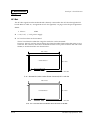
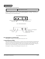
Required Clearance
5cm
5cm
Rev.A
General Features 1-11
Confidential
1-12 General Features
Rev.A
Confidential
Developer's Guide SR-600
Chapter 2
OS and Driver Setup
Supporting OS
SR-600 is supported with following OS listed below.
•
MS-DOS 6.2 (See section 2-1.)
•
Microsoft Windows 95 (See section 2-4.)
•
Microsoft Windows 98 (See section 2-9.)
•
Microsoft Windows NT Workstation 4.0 (See section 2-13.)
•
Microsoft Windows 2000 (It will be supported in the near future) (See section 2-20.)
MS-DOS
Accompanying Software
The software listed below is pre-installed in the system. The utilities setup is not performed.
Also, the language indicated in the parentheses is available. If your language for the utilities is
not available, English is used instead. For example, English version of DM-MS series utility
setting is attached as a substitute for French version of MS-DOS.
•
Microsoft MS-DOS 6.2 (Japanese and other language edition : 6.20/V
Foreign edition : 6.22)
Rev.A
•
Fujitsu Touch Panel Driver 1.0 (English)
•
Realtec Network Driver 3.80 (English)
•
Matsushita CD-ROM Driver 98/05/08 version (Japanese/English)
•
EPSON DM-MSE series Setup Utility 1.00 (English)
OS and Driver Setup 2-1
Confidential
Directory Configurations
The directory configurations of Pre-installed HD Setup Drive are as follows. Volume label for
Japanese edition is "MS-DOS_6", and for other languages is "MS-DOS_6_22". Required capacity
is approximately 7MB.
\
+-- BACKUP
| +-- CDROM
| +-- MSRCFG
| +-- NETWORK
| | +-- MSLANMAN
| | | +-- DRIVERS
| | | | +-- ETHERNET
| | | | | +-- RTL8139
| | | | +-- NIF
| | | +-- NWCLIENT
| | | | +-- DOS
| +-- TOUCH
+--DOS
: Bootup File
: CD-ROM Driver Backup
: DM-MS series Setup Utility
: Network Driver Backup
: Touch Panel Driver Backup
: System File
Refer to “HDVER.TAG” on the Setup Drive root to confirm the HD version. The contents is as
follows. This file is saved in Text format and can check from the EDIT. Available LANG
(language) is Japanese, English, German, French, Italian, Spanish, Dutch, Korean, Chinese
Traditional, or Chinese Simplified. VER (Version) is organized in three sets of number
combination such as "1.00.1".
[HD Information]
MODEL=IM-600
OS=MS-DOS6.2
LANG=English
VER=1.00.1
Touch Panel Driver
The Touch Panel Driver is not installed when this unit is shipped. Simple Batch File for copying
is available. Copy it from the backup directory to use. Move the Batch File to
“C:\BACKUP\TOUCH" and type the command written below to start installation.
INSTALL C:\TOUCH[Enter]
The directory where the file is copying to can be specified to the parameter as an option, and also
can be omitted. If it is omitted, the file is copied to “C:\TOUCH". It automatically copies the file
and completes the file copying.
2-2 OS and Driver Setup
Rev.A
Confidential
Developer's Guide SR-600
Type the command written below on the prompt to install the driver.
MEDVSTD I10,P2E8,B96[Enter]
Parameter “I10" specifies IRQ 10, “P2E8" specifies I/O address 2E8h, and “B96" specifies Baud
Rate 9600.
The calibration method is as follows.
1. Move to the Touch Panel directory.
2. Type “EPCAL” then press [Enter]. Calibration utility starts.
3. Click on the points on the [+] character. The [+] character is displayed sequentially in nine
places on the screen (Top : left/middle/right, Middle : left/middle/right, Low : left/
middle/right).
4. It automatically exits the utility when the procedure is completed.
Network Driver
The driver for Microsoft Lan Manager is stored in “C:\BACKUP\NETWORK\MSLANMAN"
directory, and the driver for Novell Netware is stored in
“C:\BACKUP\NETWORK\NWCLIENT” directory. The installation instruction is indicated in
“MSLANMAN/MSLANMAN.TXT” for Microsoft Lan Manager Drive, and “NWCLIENT/
NWODIDOS.TXT” for Novell Netware Drive. Refer to those instructions for the installation.
The directories explained above is for backup and is not a directory configuration of the
document. Make sure to create an appropriate directory, then proceed the copying of the file.
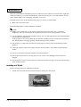
CD-ROM Driver
The CD-ROM Driver is not installed when this unit is shipped. Follow the steps below to install
the CD-ROM Driver.
1. Start “C:\BACKUP\CDROM\INSTALL.EXE”.
2. The Installation Menu Screen is displayed.
Ordinarily, item 2 is selected.
3. “AUTOEXE.BAT” Updated Selection screen is displayed.
Press “Y" then [Enter].
4.
Rev.A
Start the searching of the fie then exit.
The searching of the file is a required process for Windows, but not necessary for MS-DOS.
OS and Driver Setup 2-3
Confidential
Windows 95
Accompanying Software
The software listed below is pre-installed in the system. The language indicated in the
parentheses is available. All the languages are not prepared for the utilities. English is used as a
substitute for unavailable languages. For example, English version of DM-MS series utility
setting is attached as a substitute for French version of MS-DOS.
•
Microsoft Windows 95 950B (OSR2.1, all available languages)
•
Microsoft Windows 95 Supplement (USB Supplement/Y2K Supplement/MS-IME97/
IME 97 Updater/IrDA INF File etc, each languages)
•
INTEL Chipset INF Utility 2.20.0006 (English)[Note 1]
•
EPSON Touch Panel Driver 1.00 (English)
•
Chipset & Technologies Display Driver 4.11.01.2500 (all available languages)
•
Realtec Network Driver 5.374.0214.2000 (English)[Note 2]
•
EPSON DM-MS series Setup Utility 1.00 (Win version, English), 1.00 (DOS version,
English)[Note 2]
•
EPSON Logon Utility 1.02 (English)[Note 2]
•
EPSON OPOS ADK 1.96 (Japanese/English)[Note 2]
•
EPSON TM Driver 2.01 (Japanese/English/Chinese Traditional/Chinese
Simplified)[Note 2]
[Note 1]Required to recognize the bridge, USB Controller, and IDE Controller. Set up is completed.
[Note 2]It is not setup.
2-4 OS and Driver Setup
Rev.A
Confidential
Developer's Guide SR-600
Directory Configurations
The directory configurations of setup drive are as follows. Volume label is "Windows 95" and
the initial required capacity is approximately 400MB.
\
+-- BACKUP
| +-- CHIPSET
| +-- MSRCFG
| | +-- DOS
| | +-- WIN
| +-- LOGON
| +-- NETWORK
| +-- OPOSADK
| +-- RECOVERY
| | +-- DATA
| | | +-- RESTORE
| | +-- BOOTFD
| |
+-- DATA
| +-- TOUCH
| +-- TMDRV
| +-- VIDEO
| +-- WIN95SUP
+-- ProgramFiles
+-- WINDOWS
: Bootup File, Version File (Note 1)
: Chipset INF Utility Backup
: MSR Setup Utility Backup
: for DOS
: for Windows
: Software Keyboard Utility Backup
: Network Driver Backup
: OPOS ADK Backup
: Recovery Media Backup
: Touch Panel Driver Backup
: TM/DM Driver Backup
: Video Driver Backup
: Supplement Backup
: Windows 95 Utility
: Windows 95 File
Note 1)The contents of Version File (HDVER.TAG) are as follows.
[HD Information]
MODEL=IM-600: Model Name
OS=Windows95: OS Name
LANG=English: Language = English
Japanese
German
French
Italian
Spanish
Dutch
Korean
Chinese Traditional
Chinese Simplified
Rev.A
OS and Driver Setup 2-5
Confidential
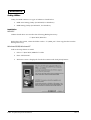
Initial Setup
The environment setting is proceeded following the steps below when you turn on the PC.
1. The program prompts you to enter the Windows owner’s name and the comapny name.
Enter the names and press the Next button.
2. The Software Licensing Agreement is displayed. Check on the [Agree] radio box and press
the Next button.
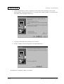
3. The program prompts you to enter the Product Key. Enter the product key listed on the
front page of First Step Guide contained in the COA(Certificate of Authenticity) package
supplied with OS package, then press the Next button.
4. Information data input is completed. Press the [Done] button.
5. Set the Date, Time, and Time Zone.
Make sure to set the correct date and time. The standard setting may not match with your
environment.
6. Printer setup.
It is not necessary to setup the printer here. You can setup the printer later.
7. Tour utility is executed.
The document about the Y2K is displayed after the execution of tour utility. Read the
document and install it if it’s necessary.
CAUTION:
65536 colors is already set for DSTN LCD model same as TFT LCD model.
It performs setup for SR-600 when it is initially setting up. Therefore, it takes additional 20
to 30 seconds to display the Windows desktop.
Device recognition is performed for the initial setup depending on the system
configuration (change in system configuration, not connectiing PS2 Mouse, etc). It may
require a Driver file depending on the device. Follow the installation steps below or the
manual comes with device for the installation.
From the second setup, the warning dialog “Mouse is not conncted” appears. Check
on the check box and click [OK]. The dialog does not appear from the next setup.
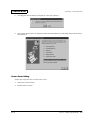
Chipset INF Utility Installation
Follow the steps below to install the Chipset INF Utility:
1. Start C:\BACKUP\CHIPSET\SETUP.EXE.
Welcome Screen is displayed.
2. Click on the [Next] button.
The Software License Agreement Screen is displayed.
2-6 OS and Driver Setup
Rev.A
Confidential
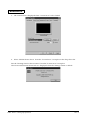
3.
Developer's Guide SR-600
Click on [Yes]button, only if you agree with the agreement.
The Readme Screen is displayed.
4. Read the text and click on [Next] button.
Then copying of file is executed. The Setup Complete Screen is displayed when the copy is
completed.
5. Select "Yes, I want to restart ....” , then click on [Finish] button.
6. It reboots the system and starts the Device Recognition.
IDE Device Wizard Screen is displayed.
7. Click on [Next] button.
8. Wizard finds Driver from the Inf Folder. Click on [Finish] button.
9. The program finds the Primary and Secondary IDE Controllers, and the computer reboot.
Confirmation Screen is displayed. Click on [No] button and continue with the Wizard.
10. Desktop is displayd and the Computer Reboot Confirmation Screen appears when a device
recognition is completed. Click on [Yes] button and reboot the system.
Display Driver Installation
Follow the steps below to install the Display Driver.
1. Start C:\BACKUP\VIDEO\W95500.EXE.
The Welcome Screen is displayed.
2. Click on [Next]button.
The Software License Agreement is displayed.
3. Click on [Yes]button, only if you agree with the agreement.
Then copying of file is executed. The Setup Complete Screen is displayed when the copy is
completed.
4.
Select "Yes, I want to restart ....” , then click on [Finish] button.
5. It reboots the system.
Change the settings from the [Control Panel:Display Properties:Settings Tab] if necessary.
Network Driver Installation
Follow the steps below to install the Network Driver.
1. Network Device is found and the Wizard Screen is displayed during the Windows Bootup.
Click on [Yes]button.
2. Driver is not found, if it is the initial installation of the Network Driver. Click on [Other
Locations]button. Select Other Location Screen is displayed. Type
C:\BACKUP\NETWORK and click on [OK]button.
3. Realtek RTL8139(A/B/C/8130) PCI Fast Ethernet NIC is found. Click on [Finish]button.
Rev.A
OS and Driver Setup 2-7
Confidential
4. Copying of Files Screen is displayed. Type C:\BACKUP\NETWORK, and click on
[OK]button. It starts the Driver installation.
5. The program prompts you to enter “Computer Name" and “Workgroup Name”. Click on
[OK]button.
The Network Screen is displayed.
6. Enter an appropriate Computer Name and Workgroup Name. Click on [Close]button.
7.
If it requests the Windows CD-ROM, type C:\WINDOWS\OPTIONS\CABS and click on
[OK]button.
8. The program prompts you to reboot the system after the driver installation. Click on
[Yes]button and reboot the system.
After reboot the system, the Enter Network Password Screen is displayed.
9.
Enter an appropriate User Name and Password. Click on [OK]button.
The Password Check Screen is displayed.
10. Enter the Password again and click on [OK]button.
2-8 OS and Driver Setup
Rev.A
Confidential
Developer's Guide SR-600
Windows 98
Accompanying Software
The software listed below is pre-installed in the system. The language indicated in the
parentheses is available. All the languages are not prepared for the utilities. English is used as a
substitute for unavailable languages. For example, English version of DM-MS series utility
setting is attached as a substitute for French version of MS-DOS.
•
Microsoft Windows 98 4. 10. 2222 A (Scond Edition, all available languages)
•
EPSON Touch Panel Driver 1.00 (English)
•
Chips&Tech Display Driver 4.11.01.2600 (all available languages)
•
Realtec Network Driver 5.367.0901.1999 (English)[Note 1]
•
EPSON DM-MS series Setup Utility 1.00 (Win version, English), 1.00 (DOS version,
English)[Note1]
•
EPSON Logon Utility 1.02 (English)[Note 1]
•
EPSON OPOS ADK 1.96 (Japanese/English)[Note 1]
•
EPSON TM Driver 2.01 (Japanese/English/Chinese Traditional/Chinese
Simplified)[Note 1]
[note 1]It is not setup.
Rev.A
OS and Driver Setup 2-9
Confidential
Directory Configurations
The directory configurations are as follows:
\
+-- BACKUP
| +-- LOGON
| +-- MSRCFG
| | +-- DOS
| | +-- WIN
| +-- NETWORK
| +-- OPOSADK
| +-- RECOVERY
| | +-- DATA
| | | +-- RESTORE
| | +-- BOOTFD
| |
+-- DATA
| +-- TOUCH
| +-- TMDRV
| +-- VIDEO
+-- My Documents
+-- ProgramFiles
+-- WINDOWS
: Bootup File, Version File (Note 1)
: Software Keyboard Utility Backup
: MSR Setup Utility Backup
: for DOS
: for Windows
: Network Driver Backup
: OPOS ADK Backup
: Recovery Media Backup
: Touch Panel Driver Backup
: TM/DM Driver Backup
: Video Driver Backup
: Windows 98 Document
: Windows 98 Utility
: Windows 98 File
note 1)The content of Version File (HDVER.TAG) is as follows.
[HD Information]
MODEL=IM-600: Model Name
OS=Windows98: OS Name
LANG=English: Language = English
Japanese
German
French
Italian
Spanish
Dutch
Korean
Chinese Traditional
Chinese Simplified
2-10 OS and Driver Setup
Rev.A
Confidential
Developer's Guide SR-600
Initial Setup
When the PC main power is turned on, the environmental setting is executed as described
below.
1. The IME Tutorial starts in the double byte language editions.
Click on [ESC] key to cancel the Tutorial.
2. The program prompts you to enter the Windows owner’s name. Input the name; then click
on [Next]button.
The Software License Agreement is displayed.
3. Check on [Agree] radio button and click on [Next]buton.
4. The program prompts you to enter the Product-Key. Enter the Product-Key listed on the
front page of the First Step Guide packed in the COA(Certificate of Authenticity) package
that comes with the OS Package. Click on [Next]button.
Information input is completed.
5. Click on [Finished]button.
6.
Set the date, time and time zone.
The successfully standard setting may not match with your setting environment. Check the
setting carefully.
7.
After this update, the environmental setting is successfully completed.
CAUTION:
65536 colors is already set for DSTN LCD model same as TFT LCD model.
It performs setup for SR-600 when it is initially setting up. Therefore, it takes additional 20
to 30 seconds to display the Windows desktop.
Device recognition is performed for the initial setup depending on the system
configuration (change in system configuration, not connectiing PS2 Mouse, etc). It may
require a Driver file depending on the device. Follow the installation steps below or the
manual comes with device for the installation.
From the second setup, the warning dialog “Mouse is not conncted” appears. Check
on the check box and click [OK]. The dialog does not appear from the next setup.
Rev.A
OS and Driver Setup 2-11
Confidential
Video Driver Installation
Follow the steps below to install the Video Driver.
1. Start C:\BACKUP\VIDEO\W98600.EXE .
The Welcome Screen is displayed
2. Click on [Next]button.
The Software License Agreement Screen is displayed
3. Click on [Yes]button, only if you agree on the agreement.
Then the files are copied. The Setup Complete Screen is displayed when the copy is
completed.
4. Select "Yes, I want to restart ....” , then click on [Finish]button to reboot the system.
5. It reboots the system and starts the Device Recognition. Change the settings from the
[Control Panel:Display Properties:Settings Tab] if necessary.
Network Driver Installation
Follow the steps below to install the Network Driver.
1. If the Network Device is found during the Windows Bootup, Wizard Screen is displayed.
Click on [Next] button.
2. Select [Display a list of all the device ....], then click on [Next]button.
3. Select Network adapters and click on [Next]button.
The Select Device Screen is displayed.
4. Click on [Have Disk]button.
5. Install From Disk screen is displayed. Type C:\BACKUP\NETWORK and click on [OK]
button.
6. Device Model Name is displayed. Click on [OK]button.
It goes back to the Wizard screen.
7. Click on [Next]button.
8. It asks you to insert the Disk. Click on [OK]button.
Copying Files screen is displayed.
9. Type C:\BACKUP\NETWORK and click on [OK]button.
It starts the driver installation.
10. Click on [Finish]button.
11. It asks you to reboot the system. Click on [Yes]button and reboot the computer.
After rebooting the system, Network Password Screen is displayed.
2-12 OS and Driver Setup
Rev.A
Confidential
Developer's Guide SR-600
12. Enter an appropriate User Name and Password and click on [OK]button.
13. Password Check Screen is displayed. Enter the Password again and click on [OK]button.
Windows NT 4.0
Accompanying Software
The software listed below are pre-installed in Windows NT Workstation 4.0 pre-installed HDD.
•
Microsoft Windows NT Workstation 4.0( all available languages)
•
Microsoft Windows NT Service Pack 4( all available languages) [Note 1]
•
Microsoft Windows NT Service Pack 5( all available languages)[Note 1]
•
Microsoft Windows NT Service Pack 6( all available languages)[Note 1]
•
Microsoft Internet Explorer 4.01 Service Pack2( all available languages)
•
Microsoft Data Access Components 2.0 Service Pack1( all available languages)
•
Microsoft Windows NT 4.0 Service Pack4 Y2K Update( all available languages)[ Note 2]
y2kupd.exe netfixi.exe
•
Microsoft Windows NT 4.0 Service Pack5 Y2K Update( all available languages)[Note 2]
netfixi.exe
•
EPSON Touch Panel Driver Ver. 1.01 (English)
•
Chips And Technologies Video Driver Ver.1.29( all available languages)
•
Realtek Network Driver Ver.4.364.0719.1999(English) [Note 3]
•
EPSON DM-MS series Setup Utility Ver 1.0.2(English)[Note 2]
•
EPSON Printer Driver for Windows
•
EPSON Logon Utility Ver.1.01 (English)[Note 2]
•
EPSON Screen Saver Ver.1.01 (English) [Note 2]
[note 1] :Select SP4 and SP5 installation during the setup. (Installation tool is required)
:If your language is not available in the foreign version, install the English version as a default.
[note 2] :It is not setup.
:OPOS-ADK Japanese version is applied to Japanese version Master. OPOS-ADK English version is applied to
foreign version Master.
:It automatically detects Japanese and foreign versions. (English is applied to foreign version)
[note 3] :Select the installation during the Windows setup.
Rev.A
OS and Driver Setup 2-13
Confidential
Directrory Configurations
The HDD root directory configurations are as follows (sub directory is omitted):
+-- I386
+-- Drvlib
+-- Drvlibj
+-- Program Files
+-- SP4
| +--Y2k
+-- SP5
| +--Y2k
+-- SP6
+-- Ie4
+-- Mdac
+-- Backup
| +--Msrcfg
| | +-- Win
| | | +-- Disk1
| | +-- DOS
| +--Touch
| +--Video
| +--Network
| +--Logon
| +--SSFORNT
| +--Recovery
| | +-- Data
| | | +-- Restore
| | +-- Bootfd
| | +--Data
+-- Temp
+-- WINNT
:Windows NT System(copy of Windows NT CD-ROM)
:Drivers(copy of Windows NT CD-ROM)
:JP version Drivers(copy of Windows NT CD-ROM)
:Windows NT Application
:Service Pack 4
:Y2K Update (Y2kupd.exe, netfixi.exe)
:Service Pack 5
:Y2K Update (Netfixi.exe)
:Service Pack 6
:Internet Explorer 4.01 SP2
:MDAC2.0 SP1
:
:Key Definition Utility backup
:
:
:
:Touch Panel Driver Backup (EPSON)
:Video Driver Backup
:Network Driver Backup
:Logon Utility Backup
:Screen Saver Backup
:
:HD Backup (for Recovery Media)
:Easy Restore
: Boot FD
: Boot FD Data
:
:Windows NT Workstation 4.0 System
(1) [I386], [Drvlib], and [Drvlib](available only in Japanese version) directory may be deleted after the Windows NT
application is added and the Driver is added or changed.
(2) The directories under the [Backup] directory are the backup of each driver and utility, which can be backed up
by copying them to the FD or the like. These directories may be deleted after the backup is completed
(3) For the Japanese version, refer to the each version of directory configurations for the details of folder under
C:\backup\oposoadk. For foreign version, each module exists under oposadk directory. (The directories for
each versions does not exist.)
(4) SP4, SP5, and SP6 directories are used to install the Service Pack 4, Service Pack 5, and Service Pack 6,
respectively. These directories may be deleted if the installation of these service packs is not necessary.
(5) The [Y2K] directory under the SPx directory is used to apply Y2K compliance to each Service Pack.
(6)The [Ie4] directory is used to install or uninstall Internet Explorer 4.01. This directory may be deleted if the
installation or uninstalled of Internet Explorer 4.01 is not necessary.
(7) The [Mdac] directory is used to install Data Access Components 2.0. This directory may be deleted if the
installation of Data Access Components 2.0 is not necessary. The MDAC2.0 cannot be uninstalled.
2-14 OS and Driver Setup
Rev.A
Confidential
Developer's Guide SR-600
Initial Setup
Follow the steps below to set up the system.
1. Turn on the power, and boot the system from the pre-installation HDD.
Windows NT Setup (GUI Mode Setup) starts.
2. Select the necessary options and install. Follow the instructions of the GUI Mode Setup.
3. Select LCD Panel Type.
4. Select Service Pack Install.
Reboot the system if Service Pack 4 or the advanced version is installed.
5. Select Windows NT from the Boot Loader Menu, and start Windows NT.
6. Log on to the system using the Administrator.
The installation of the IE4.01 and MDAC2.0 starts.(Entry is not required during the
installation of the IE4.01 and MDAC2.0.)
The system will automatically reboot after the installation is completed. The log-on operation
will be normal from the next startup of Windows NT.
CAUTION:
VGA Mode setup is executed.
The keyboard must be connected before starting the setup as the touch panel cannot
be used until all the settings are completed and the system is rebooted. Even when the
touch panel cannot be used, the keyboard must be used to log on to Windows NT for
startup of the log-on process by using the CTRL+ALT+DEL keys and for the user
authentication.
If log-on utility is installed, Keyboard connection can be logged on with log-on utility
and is not necessary.
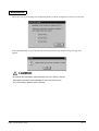
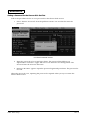
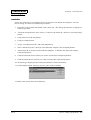
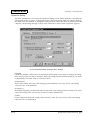
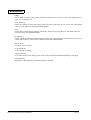
Service Pack Installation
Start up the following dialogue box for selecting the service pack to be installed in the setup
process of Windows NT.
Rev.A
•
The style of the dialogue box should be such that no system menu is included and the
size of the window is fixed.
•
Attempting to exit out of the dialogue box by pressing the ALT+F4 keys will be ignored.
•
In the startup process of this dialog box, the Service Pack is not selected.
OS and Driver Setup 2-15
Confidential
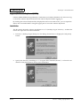
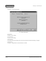
Select the service pack and press the [Install] button, and the installation of Service Pack starts.
If the [Install] button is pressed without selecting Service Pack, the following message will
appear.
CAUTION:
Re-installation is possible after OS setup for each Service Packs.
Y2K Update Module is not installed for each Service Packs.
(If it’s necessary, install it after OS setup.
2-16 OS and Driver Setup
Rev.A
Confidential
Developer's Guide SR-600
Video Driver Installation
Follow the steps below to install the Video Driver.
1. Open the control panel and select “Screen”.
2. Set the Driver Disk into FDD.
3. Select “Display Category” from the “Display Setting”.
4. Click on “Change” button and click on “Disk in Use(Have Disk)”.
5. Select Chips Video Accelerator (65545/48/50/54/55 68554 69000) , then type “OK".
Starts the installation.
6. After the installation, reboot the system.
Network Driver Installation
Follow the steps below to install the Network Driver.
1. Open the control panel and select “Network".
2. Set the Driver Disk into FDD.
3. Select “Add” from the “Adapter”.
4. Click on “Disk in Use(Have Disk)”.
5. RTL8139(A/B/C/8130)PCI Fast Ethernet Adapter, then type “OK".
6. Select (1) AUTO for Duplex Mode.
7. After the installation, reboot the system.
OS Master Recovery
Creation of the Recovery Media
CD-ROM for recovery is not included with the system. It is recommended to back up the
recovery following the steps below.
❏ Creation of the startup disk.
1. Start the MS-DOS prompt.
2. Move to C:\backup\recovery\bootfd director.
3. Execute the Makefd.bat file.
4. Insert a floppy disk into the FDD.
5. Press Enter key. (Formatting will start.)
Rev.A
OS and Driver Setup 2-17
Confidential
6. When asked whether another floppy disk should be formatted or not, press the N key.
7.
❏
When the message that the formatting is over appears, quit the MS-DOS prompt.
Saving the HD image data.
Save all the data in the C:\backup\recovery\data directory in other media or drive.
(Example)
1. Make a network connection to a PC that can write the SR-600 data onto a CD-R.
2. Save all data under the C:\backup\recovery\data directory of the SR-600 to the PC.
3. Write all the data saved in the step 2 above into a CD-R.
4. The data under the C:\backup\recovery directory may be deleted after the data is
saved.
❏
Saving the POS and UniMini data.
As the OPOS and UniMini data are not saved in the image data saved in “Saving the HD
image data”.
Save all data contained in the C:\backup\oposadk and C:\backup\Tmdrv directories in other
media or drive.
Note:
The directories under the [c:\backup] directory are the backup of each driver, which can be backed up
by saving them individually.
2-18 OS and Driver Setup
Rev.A
Confidential
Developer's Guide SR-600
Recovery Method
❏
Edit of the startup disk.
Edit the [CONFIG.SYS] and [AUTOEXEC.BAT] files created in previous section “Creation of the
recovery media” according to the device in which the image data was saved.
❏
Recovery
1. Connect the media or drive in which the data was saved in the previous section “Creation of
the recovery media” to the SR-600.
2. Use the startup FD created in the previous section “Creation of the startup disk” to reboot
the system.
3. Type "x: enter". ("x" is the drive which contains the image file).
4. Execute the [Start.bat] file.
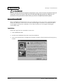
When the title of EasyRestore appears and then the startup screen appears with the EPSON
logo.
5. Select [continue].
Execute the setup of the OS after the OS is recovered.
6. Resume [OPUS] and [UniMini] saved in “Creation of the recovery media” to the
[C:\Backup] directory.
CAUTION:
Saving the image data requires 500 to 600MB. 3GB capacity is required for Windows
2000. Therefore, select the CD-ROM, MO, Server or other media having a large
capacity for saving.
HD image data file (HDIMG002.PQI) cannot be partitioned due to the EasyRestore
limitation.
EasyRestore runs only on MS-DOS. Therefore, the saving device as described in “Saving
the HD image data” should be recognized by MS-DOS.
If the system is booted from the internal hard disk of the SR-600, it cannot be recovered.
Rev.A
OS and Driver Setup 2-19
Confidential
Windows2000
Accompanying Software
The following is pre-installed in Windows 2000 Professional pre-installed HDD for IM-600.
•
Microsoft Windows 2000 Professional
•
Microsoft Windows 2000 Professional Multilanguage Version [Note 2]
•
EPSON Touch Panel Driver Ver.1.00.0 (English)
•
EPSON DM-MS series Setup Uility Ver 1.0.2 (English) [Note 1]
[note 1) It is not setup.
[note 2) Japanese version is not available.
2-20 OS and Driver Setup
Rev.A
Confidential
Developer's Guide SR-600
Directrory Configurations
The HDD route directory configurations are as follows (sub directory is omitted):
+-- I386
+-- BOOTDISK
+-- MUI
: Windows 2000 System(copy of Windows 2000CD-ROM)
: Windows 2000 SETUP Start Disk
: Windows 2000 Multilanguage
(copy of Windows Multilanguage Version CD-ROM)
| +--NL.MUI
: Netherlandic
| +--FR.MUI
: French
| +--GER.MUI
: German
| +--IT.MUI
: Italian
| +--ES.MUI
: Espana
| +--KOR.MUI
: Korean
| +--CHT.MUI
: Chinese(Traditional)
| +--CHS.MUI
: Chinese(Simplified)
+-- Backup
:
| +--Msrcfg
: DM-MS series Setup Utility Backup
| | +-- Win
:
| | | +-- Disk1
:
| | +-- DOS
:
| +--Touch
: Touch Panel Driver backup ( )EPSON )
| +--Recovery
:
| | +-- Data
: HD Backup (for Recovery Media)
| | | +-- Restore : Easy Restore
| | +-- Bootfd
: Boot FD
| | | +-- Data
: Boot FD Data
+-- Documents and Settings
: Windows 2000 User Setting
+-- Program Files
: Windows 2000 Application
+-- WINNT
:( Windows 2000 Professional System)
(1) The directories under the [Backup] directory are the backup of each driver and utility, which can be backed up
by copying them to the FD or the like. These directories may be deleted after the backup is completed.
(2) MUI Directory is not available for Japanese version.
(3) KOR.MUI, CHT.MUI, and CHS.MUI is not available for Western version.
(4)NL.MUI, FR.MUI, GER.MUI, IT.MUI,and ES.MUI are for Asia version.
(5) You may delete the languages from the MUI directory if it is not necessary.
OS Master Recovery
Follow the same steps as WindowsNT 4.0 for Creation of recovery media and recovery method.
Refer to the "OS Master Recovery” (see section 2-17).
Rev.A
OS and Driver Setup 2-21
Confidential
2-22 OS and Driver Setup
Rev.A
Confidential
Developer's Guide SR-600
Chapter 3
BIOS Setup
The system ROM of the SR-600 incorporates the following utilities related to the BIOS. These
utilities are explained in this chapter.
❏ BIOS Setup Utility (Refer to page 3-1)
❏ Power On Self Test (POST) (Refer to page 3-11)
❏ Device Diagnostic Utility (Refer to page 3-15)
BIOS Setup Utility
BIOS set up utility is used to configure the system operating environment. When you use the
SR-600 for the first time, be sure to execute this program and set the operating environment. Use
this program also when you want to change the operation environment.
Setup and Exit
How to Set up
Follow the steps below to run the BIOS setup utility:
1. Connect the keyboard to the keyboard/mouse connector.
2. Turn on the power supply of the SR-600 to setup.
3. Press the "DEL" key during the Power On Self Test during the POST process. BIOS setup
starts.
How to exit
Follow the steps below to enable the new configuration and exit the BIOS Setup utility:
1. Display the main menu of BIOS setup utility .
2. Select “SAVE & EXIT SETUP” and press Enter key.
3. The message “Save and EXIT (Y/N)?” appears. Press the Y key and then Enter key. The BIOS
Setup utility finishes and the system reboots with the new configuration enabled.
Follow the steps below to cancel the new configuration and exit the BIOS Setup utility.
1. Display the main menu of BIOS Setup utility.
2. Select “EXIT WITHOUT SAVING” and press Enter key.
3. The message “Quit Without Saving (Y/N)?” appears. Press the Y key and then Enter key.
The BIOS Setup utility finishes and the system reboots with the new configuration cancelled.
Time &Date setting is also updated.
Rev.A
BIOS Setup 3-1
Confidential
CAUTION:
Do not change any BIOS settings unless it is necessary. Also do not change the settings
specified as “Do not change” in this manual. If you change them, the SR-600 may not
operate normally.
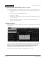
Basic Operation
Help
Press the F1 key to display the options of the items displayed inversely and the default setting
value. Press F1 again or the Esc key to exit the help window.
Changing settings
To select an item, move the cursor (using an arrow key) to the desired field. Then select the
value of the selected field with +(Page Up) or - (Page Down) key. Run the Save & EXIT SETUP
command from the main menu. All the current indicated values are saved.
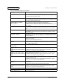
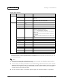
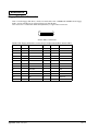
Main Menu
The following items can be selected from the BIOS setup main menu :
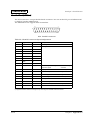
Table 3-1 BIOS Main Menu
Item
Contents
STANDARD CMOS SETUP
Standard BIOS setup menu
(See table 3-2)
BIOS FEATURES SETUP
Expansion BIOS setup menu
(See table 3-3)
CHIPSET FEATURES SETUP
It sets the items that rely on the chipset on the motherboard. As the optimum
parameters are normally set by executing [LOAD SYSTEM DEFAULT], these settings
should not need to be modified.
(See table 3-4)
POWER MANAGEMENT SETUP
It sets the items related to power management.
PNP/PCI CONFIGURATION
Performs the IRQ number, the DMA assign method and other resource
configurations. Do not change the default settings [Auto]under normal
conditions.
(See table 3-6)
LOAD BIOS DEFAULTS
Loads the minimum default values required for boot-up purposes that are
recorded beforehand in the BIOS ROM. This function has been provided for
troubleshooting purposes. The execution of this function has no effect on the
[STANDARD CMOS SETUP] parameters.
LOAD SETUP DEFAULTS
Loads the optimum default values for the SR-600. Setup default assures the perfect
performance of SR-600. If the contents of the CMOS are erased owing to longterm storage without the system being used, this function must be used to restore
the default settings. If the CMOS settings are erased, a message will be displayed
during the boot-up. The execution of this function has no effect on the
[STANDARD CMOS SETUP] parameters.
INTEGRATED PERIPHERALS
It sets the items related to I/O sub system, such as the controller for ptional
devices.
(See table 3-7)
SUPERVISOR PASSWORD
Enables a password to be set, changed, or canceled for system and BIOS setup
utility security purposes. Without Supervisor Password, BIOS setup utility cannot be
activated.
(See “PASSWORD”)
3-2 BIOS Setup
(See table 3-5)
Rev.A
Confidential
Developer's Guide SR-600
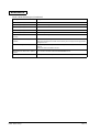
Table 3-1 BIOS Main Menu
Item
Contents
USER PASSWORD
Enables a user password to be set for use of the system. This can be used to
differentiate between authority levels when multiple users are logged onto the
system.
( Refer to “PASSWORD”)
IDE HDD AUTO DETECTION
This function automatically detects the IDE Hard Disk Parameter.
SAVE & EXIT SETUP
Saves all modified values in the CMOS RAM, and exits the BIOS setup utility.
EXIT WITHOUT SAVING
Cancels all modified values, and exits the BIOS setup utility.
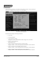
STANDARD CMOS SETUP
System clock, Calendar settings, disk drive parameter, video sub system type settings and error
types that terminate Power On Self Test (POST) can be selected from the standard CMOS setup.
Table 3-2 STANDARD CMOS SETUP Menu
Rev.A
Item
Cotents
Date/Time
It sets the date. (BIOS automatically determines the day of the week; this field is for information only.)
Press ← or → to move to the desired field (date, month, year). PgUp or PgDn increment the setting,
or type the desired value into the field.
Set the time for a 24-hour military-time clock. For example, 1 p.m. is 13:00:00. Press ← or → to move
to the desired field. Press “PgUp” and “PgDn” key to increment the value, or type the desired value
into the field.
Drive A
It sets the FDD type to be connected.
[None] is set when no FDD type is connected or cannot be detected.
IRQ6 will not be available even when [None] is set for this parameter. It is also necessary to note that
the FD will not be detected normally if different capacities have been set.
Drive C/
Drive D
BIOS can automatically detect specifications and optimal operating mode of almost all IDE hard
drives. If you select type AUTO, BIOS detects HDD specifications during POST. Set this item at AUTO
LCD & CRT
It sets the output destination for the video. Normally set at [Auto].
Auto: The CRT connection is automatically detected during boot-up.
Data is output to both CRT and LCD when a CRT is detected.
Data is output to only LCD when no CRT is detected.
Both: Data is output to Both CRT and LCD.
LCD: Data is output to only LCD.
CRT: Data is output to only CRT.
Data is output to both CRT and LCD regardless of the settings when executing POST and the BIOS
setup utility.
Halt On
You can set the BIOS to ignore certain errors during POST and continue the boot-up process. These
are the selections:
No Errors
POST does not stop for any errors.
All Errors
If BIOS detects any non-fatal error, it stops.
All, But Keyboard
POST does not stop for a keyboard error, but does for all other errors.
All, But Diskette
POST does not stop for diskette drive errors, but stops for all other errors.
All, But Disk/Key
POST does not stop for a keyboard or disk error, but stops for all other errors.
BIOS Setup 3-3
Confidential
BIOS FEATURES SETUP
It sets the basic BIOS settings, such as cache, boot-up sequence and memory shadowing.
Table 3-3 BIOS FEATURES SETUP Menu
Items
Description
Virus Warning
Disables and enables writing onto the HDD boot sector and partition table.Normally set at
[Disabled]. The system will be protected from viruses when this setting is set at [Enabled], but on
the other hand, it is necessary to note that it will not be possible to execute FDISK and FORMAT
when this setting to set at [Enabled].
CPU Internal L1
Cache
Enables and disables the CPU internal L1 cache. Normally set at [Enabled].
It is necessary to note that performance will drop when this parameter is set at [Disabled] (no
caching.)
CPU Internal L2
Cache
Enables and disables the CPU internal L2 cache. Normally set at [Enabled].
It is necessary to note that performance will drop when this parameter is set at [Disabled] (no
caching.)
CPU L2 Cache
ECC Checking
Enables and disables the CPU internal second cache (L2 cache) ECC checking. Normally set
at [Enabled].
Quick Power On
Self Test
It sets the items related to memory testing with POST (Power On Self Test) executed during bootup.
Enabled: Executes a single memory test during boot-up
Disabled: Executes three memory tests during boot-up
The memory test will be executed with three different patterns when this parameter is set at
[Disabled]. It is also possible to skip the memory tests by pressing the [ESC] key during testing.
Boot Sequence
Do not change this setting.
Boot Up Floppy
Seek
It sets whether to search or not search for the FDD during boot-up. Normally set at Disabled.
Boot-up time can be slightly reduced by setting this at [Disabled] when the boot-up is not
performed on the FDD boot such as HDD Boot.
Boot Up Num
Lock Status
It sets whether to enable or disable the keyboard's NumLock function during boot-up.
Gate A20
Option
The settings related to memory access that exceeds 1Mbyte. Normally set at [Fast].
Fast:
Gate A20 is used by the chipset, and fast memory access (which is actually a
switch between the real mode and the protect mode) is enabled.
Normal: Only enables access for conventional AT compatible systems that use a
keyboard controller.
Typematic Rate
Setting
It sets whether to enable or disable the [Typematic Delay (Msec)] and [Typematic rate (Chars/
Sec) settings.
Typematic Rate
It sets how many times per second a key is to be activated (repeated) when pressed
continuously.
Typematic
Delay
It sets the repeating interval between the 1st and 2nd pressing in units of msecs. For example, if
this parameter is set at 250ms, the key will be repeated at intervals of 250ms when pressed
continuously.
Security Option
It sets the timing for requesting password input. The following differences exist in accordance
with the setting.
System
Password input is requested with the [USER PASSWORD] setting during boot-up.
Setup
Password input is requested whenever the BIOS setup utility is started up.
VGA/SVGA
Stratching
It sets if display VGA (640 x 480)in SVGA.
3-4 BIOS Setup
Rev.A
Confidential
Developer's Guide SR-600
Table 3-3 BIOS FEATURES SETUP Menu
Rev.A
Items
Description
HDD S.M.A.R.T
Capability
It sets the HDD S.M.A.R.T function Enabled or Disabled. Normally set at Enabled. If it set at
Enabled, and the HDD does not support this function, Message is displayed on System
Configuration Screen.
Video BIOS
Shadow
It enables or disables the copying (Shadowing) of the video BIOS code from C0000h to CFFFFh
to the main memory. The purpose of shadowing is to provide high-speed execution to improve
performance by execuing the video BIOS code from the main memory. Shadowing will always
be performed with Win95/98/2000 regardless of the setting.
C8000-CBFFF,
CC000-CFFFF,
D0000-D3FFF,
D4000-D7FFF,
D8000-DBFFF,
DC000-DBFFF
Shadow
It enables or disables the copying (Shadowing) of the ROM BIOS Code on thePC Card to the
MainMemory. The purpose of shadowing is to provide high-speed execution to improve
performance by execuing the ROM BIOS Code on the PC Card from the Main Memory.
BIOS Setup 3-5
Confidential
CHIPSET FEATURES SETUP
It sets the items that rely on the chipset situated on the motherboard, such as the memory, the
bus timing and the system temperature. As the optimum parameters are normally set by
executing [LOAD SYSTEM DEFAULT], these settings need not be changed.
Table 3-4 CHIPSET FEATURES SETUP Menu
Items
Description
SDRAM RAS to
CAS Delay
It sets the Delay time after the SDRAM RAS to move to CAS. It increases Memory Access as it
reduces time interval.
SDRAM RAS
Precharge Time
This is a SDRAM version of DRAM RAS Precharge Time. It sets the CPU clock assigned for RAS
signal to store the required electric charge before the SDRAM reflesh. It increases accessibility
as it reduces value, but it may cause problems in Reflesh and loose contents of the memory if
the value is set too low.
SDRAM CAS
Latency
It sets the value of CAS Waiting Time Clock . It increases accessibility as it reduces this value.
DRAM Data
Integrity Mode
It increases reliability of Data.
System BIOS
Shadow
It sets whether to copy (shadowing) or not copy the system BIOS code between F0000h and
FFFFFh into the main memory. Normally set at [Disabled].
Enabled: Shadowing
Disabled: Non Shadowing
Performance will be improved with operating systems that perform the BIOS call, such as DOS,
Win 95, 98 and 2000, by setting this parameter to [Enabled]. On the other hand, it must be set at
[Disabled] for WinNT, which does not perform the BIOS call.
Video BIOS
Cacheable
It sets whether to cache (L2 cache) the shadowed video BIOS code.
Performance will be improved by setting this parameter to [Enabled].
Video RAM
Cacheable
It sets whether to cache (L2 cache) the shadowed video RAM (VRAM).
Performance will be improved by setting this parameter to [Enabled].
8Bit I/O
Recovery Time
It sets the 8-bit ISA timing. It is necessary to align the pace of CPU operations for bus I/O request
completion in order to ensure the speed is faster than the I/O bus. This stand-by time is known as
'recovery time.' This is usually one bus clock, but it is possible to increase this figure to stabilize
the system if the ISA bus device operations are unstable.
16Bit I/O
Recovery Time
It sets the 16-bit ISA timing. This is usually one bus clock, but it is possible to increase this figure to
stabilize the system if the ISA bus device operations are unstable.
PassiveRelease
The settings related to the chipset's PCI-ISA bridge. As the response from the ISA bus device is
not good for CPU requests, the CPU will not be able to execute other processes while waiting
for the ISA bus response, and performance will consequently be lowered. In order to solve this
problem, an ISA/EISA cycle and a CPU-to-PCI cycle are triggered simultaneously in a function
added from PCI specification revision 2.1. This is normally set at [Enabled].
Delayed
Transaction
This function is only valid for chipsets mounted with a 32-bit post write buffer, a function added
from PCI specification revision 2.1. This function releases (passively) the PCI bus during ISA bus
access that consumes approximately 50 to 60 PCI clocks. In other words, bus master access is
possible from the PCI device during ISA bus access, and this increases performance. Normally
set at [Disabled].
CPU Temp High
Limit
It sets the High Limit of Thermal Throttling by hardware.
If the setting temperature is above the High Limit, It automatically changes the CPU to Low
Power Mode and decreases CPU temperature. If the temperature is set too low or the
temperature difference to Low Limit is too little, CPU speed changes frequently and the
performance may decrease. Also, it is necessary to set the higher temperature than the Low
Limit.
3-6 BIOS Setup
Rev.A
Confidential
Developer's Guide SR-600
Table 3-4 CHIPSET FEATURES SETUP Menu
Items
Description
CPU Temp
It sets the Low Limit of Thermal Throttling by hardware.
If the setting temperature is below the Low Limit, it automatically changes CPU to Full On from
Low Power Mode. If the temperature difference with Hot Limit is too little, CPU speed changes
frequently and the performance may decrease. Also, it is necessary to set the lower
temperature than the High Limit.
Thermal Monitor
Displays CPU Junction Temperature in Celsius or Fahrenheit.
Fan Speed
Monitor
Displays revolutions of CPU fan and Power Supply Fan in RPM.
Voltage Monitor
Displays the Voltage of VTT(1.5V series), VCORE(2.0V series), 3.3V, 5V and12V.
POWER MANAGEMENT SETUP
It sets the items related to power management. Power management prolongs the battery life for
LCD backlight, HDD and other parts.
Table 3-5 POWER MANAGEMENT SETUP Menu
Rev.A
Items
Description
PM Control by
APM
It enables or disables to control the power management with the APM (Advanced Power
Management) BIOS from the OS or the application. Normally set at [Yes]. If the APM driver is
included in the operating system, power management control and the automatic power off
functions can be enabled. If the APM driver is not included in the operating system, neither the
power management control nor the automatic power off functions can be enabled even if
[Yes] is set. If [No] is set, the power management control with APM BIOS Function CAll does not
function at all.
Throttle Duty
Cycle
It sets a CPU Clock Duty during CPU Low Power Mode, Video Off Mode, and CPU Control Mode
by Thermal. CPU speed is slower as setting value gets bigger.
Video Off
Method
It sets the method for turning the video off with power management. Normally set at [V/H
SYNC+Blank].
V/H SYNC+Blank: Stops the vertical/horizontal sync signals and video signals from the video
controller. It is common for the display of monitors that support power management to also be
switched off when the vertical/horizontal sync signal is stopped.
DPMS: Controls the BIOS in accordance with the video controller's DPMS function
(Display Power Management System.) It is necessary for DPMS to be supported by the monitor.
Blank Only: Set when using monitors that only have a display off function and do not support
power management.
HDD Power
Down Timer
It sets the power down (stop the motor) timer for the HDD. The HDD enters the power down
mode when the system idles continuously for a pre-determined period
of time.The timer is reset if an access to the HDD head occurs within the set time. The default
setting is 15 minutes, and can be changed by in 1 minute increments. Also, it does not change
to the HDD power down mode from the Disabled setting.
Video Off Timer
It is same as Stand-by mode of general PC. CPU is in Low Power operation or Video Sub System
Power Down during this mode. Therefore, systems other than CPU and Video Sub System is in
Full On Mode. If the system is kept idle continuously, it sets or moves the Video Sub System to
Off mode after several minutes.
Suspend Timer
It sets the timer for shifting to the suspend mode. The system enters the suspend mode after
idling continuously for a pre-determined period of time. Suspend mode is not supported with
Windows NT. Normally set at [Disabled].
Front Switch
Function
It sets the function of the main power switch (front switch) during the power on status. When the
front power switch is pressed during the power off status, it always turns on the SR-600.
Power Off
: Forced power off
APM Power Off
: Tells the APM BIOS that an event occurs.Usually the application uses this
notice for some operation.
The default setting is APM Power OFF.
BIOS Setup 3-7
Confidential
Table 3-5 POWER MANAGEMENT SETUP Menu
Items
Description
Wake On LAN
It enables or disables the Power On via the network (LAN).
The default setting is “Disabled.” When this parameter is set at [Enabled] the power will be
switched on automatically in the same way as when the power on operation is performed with
the front switch when a special packet, known as the 'Wakeup Packet,' is received from the
host.
CPU Low Power
Timer
CPU is operating in Low Power(Speed) during this mode. Therefore, systems other than CPU is in
a Full On Mode. If the system is kept idle continuously, it sets or moves the System to CPU Low
Power Mode after several minutes.
BIOS Timer
Reload Events
It sets the event to reset the [HDD PowerDownTimer] and the [Suspend Timer].
The reload events contains the following:
IDE Primary Master:
Occurrence of access to the IDE primary master
IDE Primary Slave:
Occurrence of access to the IDE primary slave
Serial Port 1 and 2:
Occurrence of access to the serial port (COM1/2)
Serial Port 3 and 4:
Occurrence of access to the serial port (COM3/4)
Floppy Disk:
Occurrence of access to the FDD
Parallel Port:
Occurrence of access to the parallel port
Default settings:
IDE Primary Master:
Enabled
IDE Primary Slave:
Disabled
Serial Port 1 and 2:
Enabled
Serial Port 3 and 4:
Enabled
Floppy Disk:
Disabled
Parallel Port:
Disabled
PNP/PCI CONFIGURATION
Performs the IRQ, the DMA assign method and other resource configurations. Normally, the
default settings do not need to be changed.
Table 3-6 PNP/PCI CONFIGURATION Menu
Items
Description
PNP OS Installed
It sets whether the installed OS supports PnP (Plug & Play). Normally set at [Yes].
Resources
Controlled By
It sets whether PnP (Plug 6 Play) is to be performed for IRQ, DMA, I/O address and other system
resource assignations. Normally set at [Auto]. The minimal system resources are assigned and
BIOS is automatically performed when this parameter is set at [Auto], and this status is notified
to the OS to enable it to succeed to this mode. However, there are cases when automatic
setting with the PnP BIOS prevents the IRQ parameters and common parameters from being set
at the required values. In this event, change the setting to [Manual] and then make the
required settings manually with [IRQ#/DMA# assigned to] or the OS. Also, it is necessary to use
[IRQ#/DMA# assigned to] in order to make manual settings when legacy devices that do not
support Plug & Play are in use.
Reset
Configuration
Data
It sets whether to reset the PnP-related information logged in the ESCD block (Extended System
Configuration Data) on subsequent boot-ups. Normally set at [Disabled].This parameter will be
automatically restored to the [Disabled] setting on the next boot-up when set at
[Enabled].
3-8 BIOS Setup
Rev.A
Confidential
Developer's Guide SR-600
Table 3-6 PNP/PCI CONFIGURATION Menu
Items
Description
IRQ#/DMA#
Assigned To
Enables the IRQ and DMA assignations to be set manually when [Resource Controller By] is set
at [Manual]. The [Auto] setting is used when the required assignations cannot be selected
owing to legacy devices that do not support Plug & Play being in use. It is necessary to ensure
that no resource conflicts arise when setting this parameter. This is especially applicable when
all IRQ resources are required for serial ports and other ISA devices. On the other hand, the IRQ
resources are controlled by the PCI steering holder with PCI devices.
Used MEM Base
Addr
It sets the base address of the UMB in the expanded area (768K to 896K). Normally set at N/A. If
the values are specified, the values mean the base address.
Used MEM
Length
It sets the memory size when [Used MEM Base Addr] is set to other than N/A. Normally 8K bytes.
If the value is changed, the value is the memory size.
INTEGRATED PERIPHERALS
It sets the items related to the I/O ports, such as the IDE controller, the transfer mode, the serial
ports and the parallel port.
Table 3-7 INTEGRATED PERIPHERALS Menu
Rev.A
Items
Description
IDE HDD Block
Mode
It sets the sector numbers related to the block transfer mode (The block transfer mode reduces
the number of interruptions by the multi sector transfer to enable higher transfer speed).
Normally set at [Enabled].
On-chip PCI IDE
It sets whether to use or not use the IDE controller on the motherboard (chipset). Two 2.5 inch
HDDs can be connected to the primary PCI. It is also possible to connect both a CD-ROM and
a compact-flash to the secondary PCI IDE. It is possible to make available the IRQ with system
configurations that do not use IDE devices (drives) by disabling both the primary and
secondary parameters.
IDE Primary
Master PIO
It sets the transfer mode with the PIO of the IDE device connected to the IDE interface (Master).
This parameter is normally set at [Auto] and automatically sets up the optimum mode with the
auto detection function on the BIOS during POST.
IDE Primary
Slave PIO
It sets the transfer mode with the PIO of the IDE device connected to the IDE interface (Slave).
This parameter is normally set at [Auto] and automatically sets up the optimum mode with the
auto detection function on the BIOS during POST.
IDE Primary
Master UDMA
It sets the transfer mode with the DMA of the IDE device connected to the IDE interface
(Master).
This parameter is normally set at [Auto] and automatically sets up the optimum mode with the
auto detection function on the BIOS during POST.
IDE Primary
Slave UDMA
It sets the transfer mode with the DMA of the IDE device connected to the IDE interface (Slave).
This parameter is normally set at [Auto] and automatically sets up the optimum mode with the
auto detection function on the BIOS during POST.
USB Keyboard
Support
It enables or disables a USB Keyboard Legacy Support setting. If Legacy Support Enables is
selected, it is necessary to set the [Assign IRQ For USB] stting to Enable.
Onboard LAN
Support
It sets enable or disable an Onboard Ethernet usage.
Onboard
Parallel Port
It sets the I/O address and IRQ number of the parallel port (LPT1) on the motherboard.
This parameter can be selected from 3BC/IR7, 378/IRQ7 (Default), 278/IRQ5, and [Disabled].
The I/O address and IRQ number will be available if this parameter is set at [Disabled].
Parallel Port
Mode
It sets the parallel port mode. This parameter can be selected from SPP, EPP1.9+SPP, ECP,
ECP+EPP1.9, Normal, EPP1.7+SPP and ECP+EPP1.7. It is necessary to set [DMA Channel] in [ECP
Mode Use DMA] when the [ECP Mode] has been selected.
BIOS Setup 3-9
Confidential
Table 3-7 INTEGRATED PERIPHERALS Menu
Items
Description
ECP Mode Use
DMA
It sets the DMA channel when either ECP, ECP+EPP1.9 or EXP+EPP1.7 have been set with
[Parallel
Port Mode].
Onboard Serial
Port 1
It sets I/O adress and IRQ of Serial ports 1 (COM1) on the mother board.
I/O address and IRQ number are a set and can be selected from Available Option. The serial
port setting cannot be used if it sets at Disabled.
Serial Port 1
Outlet 5V
It enables or disables the 5V power supply to a serial ports 1. Set it at Enbled and proceed
power supply to use the serial port device, which requires power supply for barcode scanner
etc. Also, make sure that the power is supplied if this setting is Enabled, although [Onboard
Serial Port 1] is set at Disabled.
Onboard Serial
Port 2
It sets I/O address and IRQ of serial ports 2 (COM2) on the mother board.
I/O address and IRQ number are a set and can be selected from Available Option. The serial
port setting cannot be used if it sets at Disabled.
Serial Port 2
Outlet 5V
It enables or disables the 5V power supply to serial ports 2. Set it at Enable to use the serial port
device which requires power supply for barcode scanner etc. Also, make sure that the power is
supplied if this setting is Enabled, although [Onboard Serial Ports 2] is set at Disabled.
Onboard Serial
Port 3
It sets I/O address and IRQ of serial ports 3 (COM 3) on the mother board.
I/O address and IRQ number are a set and can be selected from Available Option. The serial
port setting cannot be used if it sets at Disabled.
Serial Port 3
Mode
It sets the serial ports 3 operational mode.
Mode 0: General Purpose (External Use) Mode
Mode 1: TM/DM-D (Internal/External Use) Mode
Mode 2: General Purpose (Internal Use) Mode
Onboard Serial
Port 4
It sets I/O address and IRQ of serial ports 4 (COM4) on the mother board.
This port is dedicated to a Touch Panel. I/O address and IRQ number are a set and can be
selected from Available Option. The serial port setting cannot be used if it sets at Disabled
3-10 BIOS Setup
Rev.A
Confidential
Developer's Guide SR-600
PASSWORD
When you select this function (SUPERVISOR PASSWORD or USER PASSWORD) from the main
menu, a message explained below appears at the center of the screen: then enter the password.
Password distinguishes upper and lowercase characters and can have up to 8 characters.
ENTER PASSWORD:
Typing a password clears any previously entered password.
The following message appears next.
CONFIRM PASSWORD:
Again, type the password and press Enter.
To clear the password, simply press Enter when asked to enter a password. Then the password
function is disabled.
To abort the process at any time, press Esc.
Power On Self Test (POST)
Power On Self Test (POST) checks the system configuration and hardware while power is on. If
it detects any errors, it issues error messages and emits audible beeps. The following section
explains the error messages.
POST Messages
During the POST, the BIOS either sounds a beep code or displays a message when it detects a
correctable error. The following is a list of POST messages. An error message may be followed
by a prompt to press F1 to continue or press DEL to enter Setup.
Table 3-8 POST Messages
Rev.A
Message
Description
Beep
The only beep code indicates a video error has occurred and BIOS cannot
initialize the video screen to display any additional information. This beep
code consists of a single long beep followed by two short beeps.
CMOS BATTERY HAS FAILED
CMOS battery is no longer functional. It should be replaced.
CMOS CHECKSUM ERROR
Checksum of CMOS is incorrect.
This can indicate that CMOS has become corrupt.
This error may have been caused by a weak battery.
Check the battery and replace if necessary.
BIOS Setup 3-11
Confidential
Table 3-8 POST Messages (Continued)
Message
Description
DISK BOOT FAILURE, INSERT SYSTEM
DISK AND PRESS ENTER
No boot device was found.
This could mean that either a boot drive was not detected or the drive does
not contain proper system boot files.
Insert a system disk into Drive A: and press <Enter>.
If you assumed the system would boot from the hard drive, make sure the
controller is inserted correctly and all cables are properly attached.
Also be sure the disk is formatted as a boot device.
Then reboot the system.
DISKETTE DRIVES OR TYPES
MISMATCH ERROR - RUN SETUP
Type of diskette drive installed in the system is different from the CMOS
definition.
Run Setup to reconfigure the drive type correctly.
DISPLAY SWITCH IS SET
INCORRECTLY
Display switch on the motherboard can be set to either monochrome or
color.
This indicates the switch is set to a different setting than indicated in Setup.
Determine which setting is correct, and then either turn off the system and
change the jumper, or enter Setup and change the VIDEO selection.
DISPLAY TYPE HAS CHANGED
SINCE LAST BOOT
Since last powering off the system, the display adapter has been changed.
You must configure the system for the new display type.
EISA Configuration Checksum Error
PLEASE RUN EISA CONFIGURATION
UTILITY
The EISA non-volatile RAM checksum is incorrect or cannot correctly read the
EISA slot.
This can indicate either the EISA non-volatile memory has become corrupt or
the slot has been configured incorrectly.
Also be sure the card is installed firmly in the slot.
EISA Configuration Is Not
Complete
PLEASE RUN EISA CONFIGURATION
UTILITY
The slot configuration information stored in the EISA non-volatile memory is
incomplete.
Note: When either of these errors appear, the system will boot in ISA mode,
which allows you to run the EISA Configuration Utility.
ERROR ENCOUNTERED INITIALIZING
HARD DRIVE
Hard drive cannot be initialized.
Be sure the adapter is installed correctly and all cables are correctly and
firmly attached.
Also be sure the correct hard drive type is selected in Setup.
ERROR INITIALIZING HARD DISK
CONTROLLER
Cannot initialize controller.
Make sure the cord is correctly and firmly installed in the bus.
Be sure the correct hard drive type is selected in Setup.
Also check to see if any jumper needs to be set correctly on the hard drive.
FLOPPY DISK CNTRLR ERROR OR
NO CNTRLR PRESENT
Cannot find or initialize the floppy drive controller.
Make sure the controller is installed correctly and firmly.
If there are no floppy drives installed, be sure the Diskette Drive selection in
Setup is set to NONE.
Invalid EISA Configuration
PLEASE RUN EISA CONFIGURATION
UTILITY
The non-volatile memory containing EISA configuration information was
programmed incorrectly or has become corrupt.
Re-run EISA configuration utility to correctly program the memory.
NOTE: When this error appears, the system will boot in ISA mode, which
allows you to run the EISA Configuration Utility.
KEYBOARD ERROR OR NO
KEYBOARD PRESENT
Cannot initialize the keyboard.
Make sure the keyboard is attached correctly and no keys are being pressed
during the boot.
If you are purposely configuring the system without a keyboard, set the error
halt condition in Setup to HALT ON ALL, BUT KEYBOARD.
This will cause the BIOS to ignore the missing keyboard and continue the
boot.
3-12 BIOS Setup
Rev.A
Confidential
Developer's Guide SR-600
Table 3-8 POST Messages (Continued)
Rev.A
Message
Description
Memory Address Error at ...
Indicates a memory address error at a specific location.
You can use this location along with the memory map for your system to find
and replace the bad memory chips.
Memory parity Error at ...
Indicates a memory parity error at a specific location.
You can use this location along with the memory map for your system to find
and replace the bad memory chips.
MEMORY SIZE HAS CHANGED
SINCE LAST BOOT
Memory has been added or removed since the last boot.
In EISA mode use Configuration Utility to reconfigure the memory
configuration. In ISA mode enter Setup and enter the new memory size in the
memory fields.
Memory Verify Error at ...
Indicates an error verifying a value already written to memory.
Use the location along with your system's memory map to locate the bad
chip.
OFFENDING ADDRESS NOT FOUND
This message is used in conjunction with the I/O CHANNEL CHECK and RAM
PARITY ERROR messages when the segment that has caused the problem
cannot be isolated.
OFFENDING SEGMENT:
This message is used in conjunction with the I/O CHANNEL CHECK and RAM
PARITY ERROR messages when the segment that has caused the problem
has been isolated.
PRESS A KEY TO REBOOT
This will be displayed at the bottom screen when an error occurs that
requires you to reboot.
Press any key and the system will reboot.
PRESS F1 TO DISABLE NMI, F2 TO
REBOOT
When BIOS detects a Non-maskable Interrupt condition during boot, this will
allow you to disable the NMI and continue to boot, or you can reboot the
system with the NMI enabled.
RAM PARITY ERROR - CHECKING
FOR SEGMENT ...
Indicates a parity error in Random Access Memory.
Should Be Empty But EISA Board
Found
PLEASE RUN EISA CONFIGURATION
UTILITY
A valid board ID was found in a slot that was configured as having no board
ID.
NOTE; When this error appears, the system will boot in ISA mode, which
allows you to run the EISA Configuration Utility.
Should Have EISA Board But Not
Found
PLEASE RUN EISA CONFIGURATION
UTILITY
The board installed is not responding to the ID request, or no board ID has
been found in the indicated slot.
NOTE: When this error appears, the system will boot in ISA mode, which
allows you to run the EISA Configuration Utility.
Slot Not Empty
Indicates that a slot designated as empty by the EISA Configuration Utility
actually contains a board.
NOTE: When this error appears, the system will boot in ISA mode, which
allows you to run the EISA Configuration Utility.
SYSTEM HALTED, (CTRL-ALT-DEL) TO
REBOOT ...
Indicates the present boot attempt has been aborted and the system must
be rebooted.
Press and hold down the CTRL and ALT keys and press DEL.
Wrong Board In Slot
PLEASE RUN EISA CONFIGURATION
UTILITY
The board ID does not match the ID stored in the EISA non-volatile memory.
NOTE: When this error appears, the system will boot in ISA mode, which
allows you to run the EISA Configuration Utility.
FLOPPY DISK(S) fail (80)
Unable to reset floppy subsystem.
FLOPPY DISK(S) fail (40)
Floppy Type dismatch.
BIOS Setup 3-13
Confidential
Table 3-8 POST Messages (Continued)
Message
Description
Hard Disk(s) fail (80)
HDD reset failed
Hard Disk(s) fail (40)
HDD controller diagnostics failed.
Hard Disk(s) fail (20)
HDD initialization error.
Hard Disk(s) fail (10)
Unable to recalibrate fixed disk.
Hard Disk(s) fail (08)
Sector Verify failed.
Keyboard is locked out - Unlock
the key.
BIOS detect the keyboard is locked.
Keyboard error or no keyboard
present.
Cannot initialize the keyboard.
Make sure the keyboard is attached correctly and no keys are being pressed
during the boot.
Manufacturing POST loop.
System will repeat POST procedure infinitely while the keyboard controller is
pull low.
This is also used for M/B burn in test.
BIOS ROM checksum error - System
halted.
The checksum of ROM address F0000H-FFFFFH is bad.
Memory test fail.
BIOS reports the memory test fail if the onboard memory is tested error.
3-14 BIOS Setup
Rev.A
Confidential
Developer's Guide SR-600
Device Diagnostics Utility
Operational check for the devices connected to the SR-600 is accomplished.
The device diagnostics utility can perform the following tests:
•
TM printer printing test
•
Customer display test
•
Cash drawer operation test
•
Serial port loop-back test
•
LPT1 port loop-back test
•
Printer connected to LPT1 printing test
•
Ethernet loop-back test
Conditions for Running Device Diagnostics
Device diagnostics utility is performed under the following conditions shown in the table.
Table 3-9 Conditions
Rev.A
Setting
Condition
Connection to the TM printer
The TM printer needs to be connected to SR-600. Connect the
printer to either COM port or LPT1, even if you will not test the TM printer.
Setting of the TM printer DIP
switches
Set the receiving buffer to maximum. Set selection switch (customer display
connection / non-connection) to non-connection (if it has a selection
switch). Set the communication settings following the instructions, if the TM
printer does not have an ID function. (ESC/POS GS I command).
Baud Rate : 9600 bps
Word Length : 8 bits
Parity : None
Refer to the TM printer manual for the setting procedure.
DM display connect port
Connect the DM display to DM display port, when the DM display is tested.
Setting of DIP switches for the DM
display
When the TM printer is connected to COM1:
Set the communication settings following the instructions, when the TM
printer has the ID function (ESC/POS GS I command).
Baud Rate: Same setting as for the TM printer (9600 bps)
Word Length: Same setting as for the TM printer (8 bits)
Parity: Same setting as for the TM printer (None)
Set the communication settings following the instructions, if the TM printer
does not have the ID function. (ESC/POS GS I command).
Baud Rate : 9600 bps
Word Length : 8 bits
Parity : None
When the TM printer is connected to another port besides COM1:
Set the DM display communication settings following the instructions.
Baud Rate : 9600 bps
Word Length : 8 bits
Parity : None
Refer to the DM display manual for the setting procedures.
BIOS Setup 3-15
Confidential
Table 3-9 Conditions
Setting
Condition
Connection to the cash drawer
Connects to the cash drawer to test the kick back operation of the drawer.
Connection to the loop back
connector
Connects the loop-back connector to the port running test, when
performing a loop-back test to LPT1.
Serial port, LPT port setting
It sets to the default setting with BIOS setup utility, when changing the setting
of serial port and LPT1 port.
Basic Operation
Starting the device diagnostics utility
To run diagnostics, press the F10 key when you start the system. The message "Diagnostics
program will execute after POST" is displayed, and the device self-diagnostic utility starts up.
Initial screen
When the device diagnostic utility starts, the following screen appears.
3-1 TM port selection
Press left or right arrow to select the port connected to the TM printer, then press enter. The
device diagnostics utility confirms the TM and DM connection and displays their status on the
screen.
The device diagnostics utility displays the option connectivity status and runs the operation test.
Follow these guidelines for using device diagnostics:
3-16 BIOS Setup
Rev.A
Confidential
Developer's Guide SR-600
❏ To display a pull-down menu, use the left arrow or right arrow key to highlight the option;
then press Enter. You also can see the pull-down menu if you press the key for the first letter
of the option. (The initialize option does not have a pull-down menu.)
❏ To select an option from the pull-down menu, use the up arrow or down arrow key to
highlight the option; then press Enter. If the option has a dialog box, you see it when you
press Enter. You also can see the pull-down menu if you press the key for the first letter of
the option.
❏ Press Esc to close a pull-down menu or a dialog box.
❏ Press the Backspace key to correct typing.
Initialize
When you select “Initialize” from the menu bar, device diagnostics restarts the program. If
device diagnostics displays “no communication” for the TM status of TM/Drawer area or DM
status of DM area, fix the problem. Then select this option to reset the program.
Exit
When “Exit” is selected from the menu, the device diagnostics is closed and the SR-600 restarts.
Device Diagnostics Utility Screen
The device diagnostics utility screen is divided into the following five areas:
❏
TM/Drawer
❏
DM
❏
COM Ports
❏
LPT1
❏ Messages
Rev.A
BIOS Setup 3-17
Confidential
TM/Drawer
The TM/Drawer area of the device diagnostics screen displays communication settings, cash
drawer driving pulse signal width, and the status for the TM printer and cash drawer.
Table 3-10 TM/Drawer Information
Setting
Description
TM model
Displays the model name, depending on the type of TM printer attached. (EPSON TM printer
with ID function only)
TM port
Displays the TM printer connection port you selected when you started device diagnostics.
TM reset signal
Indicates the signal to reset the TM printer. None is displayed, since SR-600 does not have reset
signal.
Baud rate
Indicates the baud rate device diagnostics is using to communicate with the TM printer.
Word length
Indicates the word length device diagnostics is using to communicate with the TM printer.
Parity
Indicates whether device diagnostics is using parity to communicate with the TM printer.
Drawer ON time
Displays the pulse width of the signal for opening the cash drawer.
TM status
Indicates the status of the TM printer. Refer to the “TM Status Messages” table below for more
details on the messages.
Drawer status
Displays the status (High/Low) of the cash drawer.
3-18 BIOS Setup
Rev.A
Confidential
Developer's Guide SR-600
Table 3-11 TM Status Messages
Message
Priority
Description
Disable
-
The port connected to the TM printer is disabled. Set at Enabled using BIOS setup.
No
communications
-
•Displays this message when a TM printer that does not have ID function (ESC/POS
GS I command) is connected. Check whether TM printer DIP switches are set at the
following.
Baud Rate :9600bps
Word Length :8 bits
Parity :None
Although the screen indicates “No communication,” device diagnostics can
communicate with the TM printer if DIP switches are set correctly. If something is
wrong, check the “check list” listed below.
•The device diagnostics utility cannot communicate to a TM printer that does not
have the ID function (ESC/POS GS I command).
Check the following items:
•Interface and power cables are connected to the TM properly. Be sure to turn
off the SR-600 before you connect the cables.
•The TM printer power switch is on.
•The connected TM printer was selected in the device diagnostics port.
•The TM printer is not performing a self-test when device diagnostics starts (Do
not perform self-test).
•The paper FEED button is pressed when device diagnostics starts (Do not press
the paper feed switch).
If the TM printer does not meet these conditions, correct the problem and select
the Initialize option from the menu bar.
If the printer meets all the above conditions, one of the following may have
occurred:
•The print head has overheated.
• The TM printer is not working.
•The TM printer interface circuit of the SR-600 is not operating normally.
Hardware error
1
The print head is overheated, or the printer is not working.
Paper feeding
2
The TM printer is feeding paper.
Receipt end
3
The receipt paper path contains no paper.
Journal end
4
The journal paper path contains no paper.
Paper near-end
5
The paper roll is out of paper or is not installed.
Receipt near-end
6
The receipt paper roll is out of paper or is not installed.
Journal near-end
7
The journal paper roll is out of paper or is not installed.
Cover open
8
The printer cover is open.
Online
9
The printer is online. It is possible to do a TM print test.
*If Device Diagnostics detects more than two TM status items, it displays the highest priority message. (Priority code 1 is
higher than priority code3.)
Rev.A
BIOS Setup 3-19
Confidential
DM
The DM area on the screen indicates the communication settings and status of the DM display.
Table 3-12 DM Information
Setting
Description
DM port
Indicates the port the device diagnostics utility is using to transmit data.
Baud rate
Indicates the baud rate device diagnostics is using to communicate to the DM display.
Word length
Indicates word length device diagnostics is using to communicate to the DM display.
Parity
Indicates whether device diagnostics is using parity to communicate to the DM display.
DM status
Indicates DM display status. Refer to the table below for more details .
Table 3-13 DM Status Messages
Message
Description
Disable
The setting of the port connecting the DM display is incorrect. It sets the port from BIOS
Setup.
No communication
Device diagnostics cannot communicate with the DM display. Check the TM printer and
DM display for the following:
The DM display is properly connected. Be sure to turn off the SR-600 before you connect the
cables.
•The data communications DIP switch is the same for the DM display and the TM printer.
•DM display main power switch is on.
•The DM display is not doing a self test. (Do not perform self-test.)
If DM display does not meet these conditions, correct the problem and select the Initialize
option from the menu bar. If the TM printer and DM display meet the conditions above, one
of the following may have occurred:
•DM display interface circuit on the this product is not working.
•DM display is not working.
Busy
DM display's condition is busy. It is possibly caused by the following:
•The DM display is running a self test.
•After the device diagnostics started, the DM display power was turned off.
Ready
The DM display is ready to receive data. The DM display test is possible.
COM ports
The area of the screen for COM ports lists the DTR, DSR, RTS, CTS, DCD, and RI status for each
available COM port. When the port is disabled, you see a message to that effect.
LPT port
The LPT1 area of the screen lists the BSY, ACK, PE, SLCT, and ERR status for the LPT1 port
including RDT, CLI, SDT, and CLO status for the OCIA port.
3-20 BIOS Setup
Rev.A
Confidential
Developer's Guide SR-600
Messages
The message portion of the screen displays the result of tests.
Table 3-14 Message area
Test category
Message
Description
TM printer
Disabled
This port is disabled.
Done
The TM printer test is completed. Check the printing motion and autocutter
motion.
Disabled
This port is disabled.
Done
DM display test is completed. Check display.
Disabled
This port is disabled.
Done
The drawer kick-out test is completed. Check the motion of cash drawer.
Error
The diagnostics test failed. This message also appears when a loop-back
connector is not connected or the wrong loop-back connector is connected.
Disabled
This port is disabled.
OK
The test completed successfully.
Time out
The printer connected to the LPT1 port did not enter a ready state after 2
seconds.
Disabled
This port is disabled.
Ok
The print data was sent successfully.
DM display
Drawer kick-out
Loop-back
LPT1 print
Setup Menu
Following three commands can be executed from the Setup menu.
❏ Drawer Password
It sets the password to access to the drawer kick out test.
❏ Drawer ON time
It sets the length of time for the voltage signal supplied to the cash drawer solenoid to open
it.
❏ M/B Information
Displays the various informations on the motherboard.
Rev.A
BIOS Setup 3-21
Confidential
Setting a Password for the Drawer Kick Out Test
Follow the procedures below to set a password for the drawer kick out test.
1. Select “Drawer Password” from the pull down menu. You are asked to enter the
password.
3-2 Enter Password screen
2. Enter the password to be set and press Enter. The password should be 4 to 8
alphanumeric characters. Upper and lower case characters are distinguished. The
Password must be at least 4 characters.
3. Message “Re-enter” appears. Input the password again and press Enter. The password is
now set.
When the password is set, inputting the password is required when you try to execute the
Drawer kick out test.
3-22 BIOS Setup
Rev.A
Confidential
Developer's Guide SR-600
Changing/Deleting the Password for the Drawer Kick Out Test
Follow the procedures below to change or delete the password for the drawer kick out test.
1. Select “Drawer Password” from the pull down Setup menu. You are asked to enter the
password.
2. Enter the current password and press Enter key.
3. Message “New” appears.
4. Press Enter key only to delete the password. Enter new password and press Enter key to
set a new password.
5. Message “Re-Enter” appears. Enter the password again and press the Enter key to
change or delete the password.
Setting Drawer ON time
Drawer ON time option sets the length of time for the voltage signal supplied to the cash drawer
solenoid to open.
3-3 Enter Drawer On Time screen
Select Drawer ON time option from the Setup pull down menu to set the time. The dialog box
appears. Set the length of the voltage signal required by the cash drawer in ms unit. The On
time can be set at any value within a range of 0 to 500 ms. The setting is rounded to the
minimum units that can be set by the TM that you are connected to. For the TM-930, the
minimum units are 10 ms, and for other TMs, the minimum units are 2 ms.
Please refer to the cash drawer’s manual for the appropriate value to enter.
Rev.A
BIOS Setup 3-23
Confidential
M/B Information
When the M/B Information is selected from the pull down menu, various main board
information is displayed. Press any key to close the display.
3-4 Mainboard Informations
M/B information displays following information:
•
CPU (CPU)
•
CPU speed (Speed)
•
CPU temperature (Temp)
It displays in Celsius and Fahrenheit within a range of 0 to 125 Celsius.
•
Memory capacity (Memory)
MB (megabyte) unit
•
Enable/ Disable the On Board Video Controller (Video)
Displays "Enable” in the normal operation and “Disable” in other situations.
•
Enable/ Disable the Sound Daughter Board (Sound)
Displays "Enable” in the normal operation and “Disable” in other situations.
•
Enable/ Disable the On Board Ethernet Controller (Ethernet)
Displays "Enable” in the normal operation and “Disable” in other situations.
3-24 BIOS Setup
Rev.A
Confidential
Developer's Guide SR-600
•
Enable/ Disable the Ethernet Controller Boot-ROM(ROM)
Displays "Enable” in the normal operation and “Disable” in other situations.
•
Ethernet ID(ID)
Displays 12 digit hexadecimal numbers separated by hyphens. Only a hyphen is
displayed if there is no controller.
•
BIOS version (BIOS Version)
•
Keyboard Firmware Version (K/B Firmware Version)
•
Main Board Total Run Time (M/B Total Run Time)
Displays in hours. Maximum of 1193046 hours.
•
Battery Discharge
Rechargeable for a maximum of 65535 times.
Device Test Menu
The test for each devices can be performed from the Device Tests and More Tests menu. The
device test is explained below.
❏ TM print test
The following tests are run in the TM print test.
Print test for receipt paper (Standard print pattern)
Autocutter test (restricted to those printers with Autocutter)
When the test is completed, “TM print test:done” message appears on the message area.
Make sure that the print pattern is printed. And check that the receipt paper is cut by the
autocutter if the printer is equipped with an autocutter.
TM print test is not performed if the TM Status is Disable or No communication.
❏ DM display test
Sends following messages to the DM display.
Display Module Test
**** Device Diagnostics ****
Check the DM display and make sure that the test is performed.
Press any key to finish the test. The message “DM display test: done” appears on the
message area.
DM display test is not performed if the DM Status is Disable or No communication.
❏ Drawer kick out test
Drawer kick out test opens the cash drawer. Make sure that the cash drawer board opens
normally. TM printer has drawer kick out drive signal (Signal 1 and 2). This test is effective
only for drawer kick out drive signal 1.
If the password has been set for the drawer kick out test, it asks your password to run the
drawer kick out test.
Drawer kick out test is not performed if the DM Status is Disable or No communication.
❏ COM1/COM2/COM5/COM6 loop-back
Runs data transmission test of serial port. It performs data transmission to a target port,
therefore, it is required to connect a loop-back connector to the target port. COM port test
Rev.A
BIOS Setup 3-25
Confidential
checks DTR, DSR, CTS, RTS, TXD and RXD signals.
If the test is completed normally, “OK” message appears on the message area. If the test is
failed, an error message appears.
❏ LPT1 loop-back
Performs LPT1 signal line test. It performs data transmission to a target port, therefore, it is
required to connect the loop-back connector to the target port. LPT1 port test checks STROBE, ACK, DATA0, BUSY, AUTO FEED, PAPER EMPTY, ERR, INIT, SELECT IN and
SELECT signals. The loop-back test does not test the data line. Perform the data line check
on the LPT1 print test.
If the test is completed normally, “OK” appears on the message area. If the test is failed, an
error message appears.
❏ LPT1 print test
LPT1 print test prints out the standard print pattern to the printer connected to the LPT1
port.
If the test is completed normally, “OK” message appears on the message area. If the test is
failed, error message appears.
❏ Ethernet test
Performs loop-back test of the Ethernet controller. It is not required to connect any object to
run the test, because it runs with internal loop-back function of the controller.
If the test is completed normally, “OK” appears on the message area. If the test is failed, an
error message appears.
3-26 BIOS Setup
Rev.A
Confidential
Developer's Guide SR-600
Chapter 4
Driver / Utility Specifications
Utilities for SR-600 listed below are explained in this chapter.
MS-DOS
•
•
•
•
Fujitsu Touch Panel Driver 1.0 (English)
Realtec Network Driver 3.80 (English)
Matsushita CD-ROM Driver 98/05/08 version (Japanese/English)
EPSON DM-MSE series Setup Utility 1.00 (English)
Windows95
•
•
•
•
•
•
•
•
INTEL Chipset INF Utility 2.20.0006 (English)
EPSON Touch Panel Driver 1.00 (English)
Chipset & Technologies Display Driver 4.11.01.2500 (all available languages)
Realtec Network Driver 5.374.0214.2000 (English)
EPSON DM-MS series Setup Utility 1.00 (Win version, English), 1.00 (DOS version,
English)
EPSONLogon Utility 1.02 (English)
EPSON OPOS ADK 1.96 (Japanese/English)
EPSON TM Driver 2.01 (Japanese/EnglishChinese Traditional/Chinese Simplified)
Windows98
•
•
•
•
•
•
•
EPSON Touch Panel Driver 1.00 (English)
Chips&Tech Display Driver 4.11.01.2600 (all available languages)
Realtec Network Driver 5.367.0901.1999 (English)
EPSON DM-MS series Setup Utility 1.00 (Win version, English), 1.00 (DOS version,
English)
EPSON Logon Utility 1.02 (English)
EPSON OPOS ADK 1.96 (Japanese/English)
EPSON TM Driver 2.01 (Japanese/EnglishChinese Traditional/Chinese Simplified)
Windows NT 4.0
•
•
•
•
•
•
•
EPSON Touch Panel Driver Ver. 1.01 (English)
Chips And Technologies Video Driver Ver.1.29 (all available languages)
Realtek Network Driver Ver.4.364.0719.1999 (English)
EPSON DM-MS series Setup Utility Ver 1.0.2 (English)
EPSON Windows Printer Driver
EPSON Logon Utility Ver.1.01 (English)
EPSONScreen Saver Ver.1.01 (English)
Windows2000
•
•
Rev.A
EPSON Touch Panel Driver Ver. 1.01 (English)
EPSON DM-MS series Setup Utility Ver 1.0.2 (English)
Driver / Utility Specifications 4-1
Confidential
The Driver and Utility listed below are explained in this Chapter. Refer the Chapter 2 “ OS and
Driver Setup” and Chpater 6 ”Peripherals/Option Installation” for the details of Driver and
Utility not listed below.
•
Network Driver (See section 4-3)
•
Video Driver (See section 4-4)
•
Logon (Software Keyboard) Utility (See section 4-5)
•
Screen Saver (for NT) (See section 4-7)
•
EPSON OPOS ADK (See section 4-11)
4-2 Driver / Utility Specifications
Rev.A
Confidential
Developer's Guide SR-600
Network Driver
Installation
Follow the steps below to install the Driver for NT Network. Refere the Chapter 2 “OS and
Driver Setup” for other OS installation procedures.
1. Open the Control Panel and double click “Network”. The dialog shown below is displayed.
Click [Yes] button.
2. "Network Setup Wizard” starts. Select “Connect to the Network” check box and click [Next]
button.
3. Click [Select from the list] button.
4. Click [Use Disk] button.
5. Tyepe “C:backup\network” and click [OK] button.
6. Select “RTL8139(A/B/C/8130) PCI Fast Ethernet Adapter” and click [OK] button.
7. "RTL8139(A/B/C/8130) PCI Fast Ethernet Adapter” is added to the Network Adapter.
Click [Next] button.
8. Click the Network Protocol that you want to install, then click [Next] button.
9. Click the Network Service that you want to install, then click [Next] button.
10. Next dialog is displayed, then click [next] button. It starts installation.
11. Set the Duplex Mode. Select [(1)AUTO] , then click [Continue].
12. Reboot the system after the installation.
Rev.A
Driver / Utility Specifications 4-3
Confidential
Video Driver
Chipset & Technologies Video Driver is used for DM-LS121S and DM-LS121T LCD unit.
VGA/SVGA
DM-LS121S and DM-LS121T are a SVGA (800 x 600 )panel. If it displays as VGA screen (640 x
800), the screen appears in the center of the screen and the whole screen is not displayed.The
resolution of SR-600 is set at standard VGA (640 x 480) as a default. Therefore, the resolution
needs to be set at SVGA in Windows 95/98.
Follow the steps below to adjust the resolution of LCD unit.
1. Connect with the external monitor. Open the Windows Control Panel. then change the
resolutin to 800 x 600.
2. Set the Color. 256 colors are displayed on the SVGA LCD unit. If more than 256 colors are
displayed, the resolution are set at 640 x 480.
3. Reboot the system. Press the Del key, then start the BIOS setup.
4. BIOS is updated to support the SVGA Display.
CAUTION:
Do not use SVGA BIOS in VGA LCD,or VGA BIOS in SVGA LCD. It may shorten the life of
the Display.
Back light control for VGA LCD cannnot be used in Power Management.
4-4 Driver / Utility Specifications
Rev.A
Confidential
Developer's Guide SR-600
Log on (Software Keyboard) Utility
SEGina (SEIKO EPSON Image Identify Certification) tool enables Windows NT 4.0 user to log
on from the software keyboard and use the software keyboard after logging on.
By clicking the software keyboard key displayed on the screen with mouse, you can input the
data to the executed Window. Drag the upper part to move the software keyboard.
Installation
The document about the software installation is in "C:\Backup\Logon" directory - readme file.
Follow the steps below for the installation.
1. Execute C:\backup\logon\Setup.exe. The dialog shown below is displayed. Click [Next]
button.
2. Specify the directory sinstalling to. "C:\Program Files\EPSON\SEGina\" is selected as an
default. Click [Next] button, then it starts installation.
Rev.A
Driver / Utility Specifications 4-5
Confidential
3. The dialog shown below is displayed after the installation. Select [Yes] and click [Finish],
then reboot the system.
CAUTION:
Reboot the system after installed SEGina to Windows NT 4.0. If Actinkey is executed
without rebooting the system, it may cause some problems. If any problems occur,
reboot the system.
How to use the sortware ketboard
The following three Modules are installed:
•
SEGina - Controls Logon from the Main Module
•
Logonkey - Software keyboard displayed during logon
•
Actinkey - Software keyboard displayed after logon
Logonkey is displayed with logon dialog in Windows NT 4.0 when the System is turned on.
Select Actinkey from the start menu to use software keyboard after the nstallation. Actinkey is
displayed.
Select the “Top” check box on the upper right corner of the screen, then software keyboard is
displayed on the top all the time.
To exit the Actinkey, click [x] button on the upper right corner of the screen.
4-6 Driver / Utility Specifications
Rev.A
Confidential
Developer's Guide SR-600
CAUTION:
Do not use this tool for the hardware keyboard. It may send incorrect keyboard status if
hardware keyboard is used. This tool is for 101/102/106 type keyboard. However, its
operation is not guaranteed other than Japanese or English Operation System.
Screen Saver (For NT)
This is a Windows NT dedicated screen saver. When this screen saver starts, LCD back light is
turned off. When the screen saver is closed, LCD back light is turned on. It extends the life of
LCD supplies and increases reliability. It also reduces the power consumption during the
System-idle mode.
Installation
Follow the steps below to install the screen saver.
1. Select EPSSS4NT.EXE.
2. Double click EPSSS4NT.EXE, then strat the installation.
3. The screen shown below is displayed. Check the contents of the document and click [Next]
button.
Rev.A
Driver / Utility Specifications 4-7
Confidential
4. The screen shown below is displayed after the installation. Select [Yes] radio button and
click [OK], then reboot the Windows.
Uninstallation
Follow the steps below to uninstall the screen saver.
1. Open the Control Panel.
2. Double click “Add / Delete Application”
3. Click “Installation and Delete” tab, then select “EPSON Screen Saver” from the list box.
4. Click “Add and Delete” button.
4-8 Driver / Utility Specifications
Rev.A
Confidential
Developer's Guide SR-600
5. The diagram shown below is displayed. Click [Yes] button.
6. The screen shown below is displayed after the uninstallation. Click [OK] button, then reboot
the Windows.
Screen Saver Setting
Follow the steps below to set the screen saver.
1. Open the Control Panel.
2. Double click “Screen”.
Rev.A
Driver / Utility Specifications 4-9
Confidential
3. The screen below is displayed when “Screen Saver” tab is clicked.
4. Select “EPSON Screen Saver” from the “Screen Saver” Group box in the drop down list.
Sets the "Waiting Time for the execution" from the "Screen Saver" Group box.
The Virsion information shown below is displayed when the "Setting" button is clicked.
4-10 Driver / Utility Specifications
Rev.A
Confidential
Developer's Guide SR-600
EPSON OPOS ADK
OLE (Object Linking and Embedding) is component software that runs on Win 32-bit style
operating systems, such as Microsoft Windows NT 4.0. The creation of software components
enables software reuse and backward compatibility.
The purpose of OLE POS (“OPOS”) is to use OLE to standardize the control system (API) of POS
peripherals, thereby making application and peripheral equipment control software open and
generic, OPOS standardizes the interface between POS applications and device control objects,
which in the past have differed by device and by manufacturer; it also facilitates the porting of
applications and the reconfigurations of peripheral devices.
Such standardization of peripheral devices eliminates much of the work once needed to
developsoftware. Further, it totally opens systems and makes it possible to build intelligent,
flexible POS systems affordably, not only in large retail stores but even in the smallest shops,
where POS has yet to make inroads.
OPOS makes it easy to build POS applications that take advantage of the functionality that Windows has to offer, such as graphics, video, and sound, a user-friendly GUI, and multitasking.
Refer the User’s Guide stored in the directory C:\Backup\Oposadkfor for more dtails of the
OPOS ADK installation procedure.
The creation of component software
POS devices require a control program. In the past, the device control object existed as part of a
monolithic POS application software. Because of this monolithic structure, POS systems
designers would have to replace or revise the entire POS application software just to change the
device control object when a peripheral device was changed. This, of course, was a timeconsuming and costly process. It also meant that to create device control objects, POS
application software developers had to acquire detailed technical knowledge of each
manufacturer’s devices, including their functions and command systems.
With the advent of PC-POS, however, any external device could be connected to the PC, as long
as the interface (e.g., serial or parallel) was supported. While the hardware compatibility
problem was solved, the software problem was not. Software could not be adapted and the POS
applications software itself would have to be replaced. Thus a total opening of PC-POS
systemsin terms of both hardware and software had not been achieved.
To solve this problem, the device control objects were modularized and made independent from
the POS applications software. This simplifies the process of changing the POS application
software itself when a device is replaced because now only the device control object needs to
bereplaced. In addition, by providing our own device control objects, we can lighten the burden
on our POS applications software developers, who no longer need to acquire detailed
knowledge of each manufacturer‘s device and standardize the total system, hardware as well as
software.
Rev.A
Driver / Utility Specifications 4-11
Confidential
Software standardization
When a device control object is created, it is necessary to choose the interface (API) between the
POS application software and the device control module. EPSON has joined an industry-wide
and worldwide effort to standardize and spread the use of APIs. The standardized software
usesan OCX driver, which is modularized software divided into two levels: the Control Object
(CO) and Service Object (SO).
A separate CO exists for each class of device, while a separate SO exists for each individual
device. For example, software that uses a TM-U950 needs a general POS printer CO and a
specific TM-U950 SO. If the TM-U950 printer were replaced by a TM-U375 printer, the TMU950SO would have to be replaced by a TM-U375 SO, but the rest of the software, including the
POS printer CO would remain the same. In other words, to switch from one printer to another
requires only a change in the SO.
EPSON software
The software products (OCX drivers) that EPSON offers to enable such an OPOS system are
called the EPSON OPOS ADK. The EPSON OPOS ADK provides the OCX driver and much
more. EPSON also provides custom tools to support the construction and development of an
OPOS application software development environment.
4-12 Driver / Utility Specifications
Rev.A
Confidential
Developer's Guide SR-600
Chapter 5
Hardware Specifications
Circuit Board Functions
Descriptions of the circuit board used in the SR-600 are listed below.
❏ Motherboard
The circuit board unit that contains the basic functions for the PC.
This contains CPU, chip set, memory(DIMM), Super I/O, power supply unit (DC - DC
Converter) and so on.
❏ Video board
This is connected to the motherboard and acts as a system relay on the LCD, and performs
LVDS conversion for the TFT. A single circuit board supports the TFT LCD panel and the
DSTN LCD panel.
❏ PCI board
This connects to the PCI expansion board, and is connected to the motherboard.
❏ Volumeboard circuit board
This consists of the keyboard I/F, reset switch of the SR-600, power switch and speaker
volume, and is connected to the motherboard with a cable.
❏ I/O board
The circuit board that contains the interface connectors of the external I/O consists of three
serial ports, one parallelport, USB2 port and LAN1 port.
❏ Drawer board/CRT board (Option)
The circuit board that adds 2 drawer ports and an external CRT1 port.
Rev.A
Hardware Specifications 5-1
5-2 Hardware Specifications
44 pins
Space 2
(Option)
50 pin
50 pin
Transforming
Board 44 to 50
for CD-ROM
Compact
Flash
50 pin
44 pin
44 pin
Space 1
Compact
Flash
50 pin
2.5 inch
50 pin
HDD
44 pin
44 pin
44 pin
P/S Unit
40 pin
80 pin
144 pin PCI slot
PCI Board
80 pin
80 pin
40 pin
22 pin
RJ-458 pin
40 pin
Video Board
120 pin
120 pin
For connecting
DM-D
To DSTN Display Unit
Volume
Reset SW
2 pin
Speaker
Power Switch
Volume Board
FDD
(MOLEX 26 pin)
15 pin
Drawer Port
For TFT PanelFor DSTN Panel
28 pin
To TFT Display Unit
44 pin
44 pin
ATAPI
Mother Board
CPU sub-board
I/O Board for connecting
80 pin
I/O Board
COM3
Confidential
System
System Diagram
The SR-600 system diagram is shown below.
5-1 System diagram (Motherboard)
Rev.A
Confidential
Developer's Guide SR-600
Memory Map
The SR-600 has a 256KB Flash ROM as a system ROM.
After the BIOS starts, the SYSTEM BIOS is assigned to the 64 KB space 0F0000h through
0FFFFFh and the Video BIOS is assigned to the 44KB (40KB for the IM-300) space 0C0000h
through 0CBFFFh.
RAM
100000h
Expansion Memory Range
System BIOS
System ROM Range
0F0000h
0E0000h
0CB000h
0C0000h
0B8000h
0B0000h
0A0000h
Expansion ROM Range
Video BIOS
Color
Monochrome
Video Buffer Range
Graphics
RAM
Conventional
Memory Range
000000h
5-2 Memory Map
Rev.A
Hardware Specifications 5-3
Confidential
I/O Map
The SR-600 system I/O map is PC/AT-compatible. The I/O address assignments are shown
below. The changes in the serial and parallel ports I/O addresses is available from the BIOS
setup program or Plug & Play function.
Table 5-1 I/O Map
I/O address
Description
Can be
changed
Device
00h-1Fh
DMA controller 1 (8237A)
✕
82371EB
20h-3Fh
Interruption controller 1 (8259A)
✕
82371EB
40h-5Fh
Timer/ Counter (8254)
✕
82371EB
60h-6Fh
Keyboard controller (8042)
✕
FDC37B807
70h-7Fh
Real time clock, NMI mask
✕
82371EB
90h-9Fh
DMA page register
✕
82371EB
A0h-BFh
Interruption controller 2 (8259A)
✕
82371EB
B2h-B3h
Advanced Power Management Control
✕
82371EB
C0h-DFh
DMA controller 2 (8237A)
✕
82371EB
F0h
Co-processor error
✕
82371EB
170h-177h
Hard disk controller (Secondary)
✕
82371EB
1F0h-1F7h
Hard disk controller (Primary)
✕
82371EB
2E8h-2Efh
Serial port 4
O
FDC37B807
2F8h-2FFh
Serial port 2
O
FDC37B807
376h
Hard disk controller (Secondary)
✕
82371EB
378h-37Fh
Parallel port 1 (+400h can be used when in the ECP mode)
O
FDC37B807
3B0h-3DFh
VGA register
✕
69000
3E8h-3EFh
Serial port 3
O
FDC37B807
3F0h-3F7h
Floppy disk controller (excluding 3F6h)
✕
FDC37B807
3F6h
Hard disk controller (Primary)
✕
82371EB
3F8h-3FFh
Serial port 1
O
FDC37B807
4D0h-4D1h
Interruption edge/ Level control
✕
82371EB
CF8h-CFFh
PCI configuration register (DWORD)
✕
82443BX
CF9h
Reset control (Byte)
✕
82371EB
5000-5000Ch
SMBUS I/O register
✕
82371EB
5-4 Hardware Specifications
Rev.A
Confidential
Developer's Guide SR-600
DMA
The 8237A-, which is equivalent to two DMA controllers and supports seven DMA channels, is
mounted in the SR-600. Channels 0, 1, 2, and 3 provide 8-bit data transfers; channels 5, 6, and 7
provide 16-bit data transfers. The SR-600 uses channel 2 for the floppy disk drive controller, and
releases other channels to the ISA bus.
The DMA channel assignments are shown below.
Table 5-2 DMA channel assignments
Controller
Channel
Application
DMA1 8 bits
0
(Spare)
1
(Spare *)
2
Floppy disk controller
3
(Spare *)
4
Controller 1 cascade connection
5
(Spare)
6
(Spare)
7
(Spare)
DMA2 16 bits
* When LPT1 is in ECP mode, use one of the channels.
Rev.A
Hardware Specifications 5-5
Confidential
System Interrupts
The system provides two cascade connections to 8259A-equivalent interrupt controller and
carries 15 levels of interrupts, besides NMIs. Table 5-3 shows the application for each interrupts.
However, you can change the serial and parallel interrupts from the BIOS setup program or Plug
& Play function.
Table 5-3 System interrupts
Application
Can be
changed
IRQ0
Timer
✕
IRQ1
Keyboard
✕
IRQ2
Controller 2 cascade
✕
IRQ8
RTC
✕
IRQ9
Not used
O
IRQ10
Serial port 4
O
IRQ11
Serial port 3
O
IRQ12
Mouse
O
IRQ13
Numerical operation co-processor
✕
IRQ14
Hard disk controller (Primary)
▲ *1
IRQ15
Hard disk controller (Secondary)
▲ *2
IRQ3
Serial port 2
O
IRQ4
Serial port 1
O
IRQ5
Not used
O
IRQ6
Floppy disk controller
✕
IRQ7
Parallel port 1
O
NMI
I/O error check
✕
Controller 1
Controller 2
*1: It cannot be changed when the device is in use, but can be cleared when not in use.
*2: IRQ15 is assigned in the secondary IED, but not used in SR-600.
5-6 Hardware Specifications
Rev.A
Confidential
Developer's Guide SR-600
Mother Board
ICS9245-55
ATX POWER
20pin
ICS9179-03
Volume
Amp
LM4765
14.31818MHz
15pin
FAN
RESET Signal
Speaker
RESET SW
Power ON/OFF Signal
168pin DIMM×2
Power SW
Mouse/KB
P/S Control
3pin
Socket 370
LM77
82443BX
North Bridge
LM87
From MCR
I2C-Bus
To
PCI Slot Board
PCI Bus
80pin
25.000MHz
32.768KHz
To IDE-HDD
CD-ROM
CF
E2PROM
From T/P
IDE
44pin
82371EB
RTL8139BL
FLASH ROM
South Bridge
Video Analog
1Mbit
Flash
ROM
TX/RX
To Multi Video
Board
(120pins)
USB×2
ISA Bus
KeyBoard
FDD
25pin
FDC37B80X
FDC37B80X
Parallel
Selector
TRANSE
ST-6118T
COM1
To I/O Connector Board
COM2
80pin
Driver/Receiver x 3
COM3B
DM-D
Selector
COM3A
8pin
RJ-45
Drawer/D-Sub Board
40pin
5-3 Block diagream of the mothreboard
Rev.A
Hardware Specifications 5-7
Confidential
Peripheral CPU and Memory Circuits
Memory Clock
CPU
Clock
Generator
PCI Clock
82443BX
DIMM
Host Bus
14.318MHz
DIMM
CPU Clock
Clock
Buffer
Celeron
Memory Bus
PCI Bus
5-4 Block diagram of the peripheral CPU and memory circuits
CPU (Celeron-PPGA)
An Intel Celeron processor is used. In SR-600, 370 socket type is in use.
The main specifications of the CPU are explained below. Refer to the Intel Celeron Processor
Data sheet for information on items not covered here.
Operating frequencies:
366MHz
Base clock:
66MHz (Input from the clock generator)
L2 cache:
128KB built in
Core voltage:
2.00V The core voltage is automatically set by the CPU.
(Setting a jumper is not necessary)
Memory (168pin DIMM)
Two 168-pin DIMM sockets are available, and a maximum of 256MB memory can be mounted.
The DRAM only supports the 3.3V SDRAM (synchronous DRAM.) The DIMM is used
singularly. It is possible to use two DIMMs with different capacities. It is necessary to conform
to the Intel PC SDRAM Unbuffered DIMM Specifications for the basic specifications. The
specifications are explained below.
SDRAM specifications:
5-8 Hardware Specifications
Conform to the Intel PC SDRAM specifications.
Rev.A
Confidential
Developer's Guide SR-600
Operating clock:
66MHz x 4 /sockets
(input from the chipset via clock generator)
DIMMs that support PC100 (for 100MHz clock) can also
be used.
Usable height:
36mm or less
(maximum 38.23mm in the unbuffered DIMM
specification)
Serial PD (SPD):
Must conform to the Intel PC SPD specifications
(memory information acquisition)
Operating mode:
Must support the self-refreshing mode
≤36mm
1
84
85
168
5-5 External view of the DIMM
Chip set (82443BX : North bridge)
The Intel chipset 82443BX controls CPU, memory and PCI bus. It also supports AGP bus control
function, but that is not used in SR-600. Combination of this chip set and 82371EB is called
440BX.
Rev.A
Hardware Specifications 5-9
Confidential
Peripheral I/O Circuits
PCI Bus
USB
82371EB
USB
(PIIX4E)
Primary IDE
2.5”
HDD
82C37
Secondary IDE
82C59
CF
Or
CD-ROM
82C54
CF
Or
RTC
BIOS
ROM
ISA Bus
COM4
(Touch panel)
FDC37B807
(B)
DM-LR121X
M d l
*Selection by BIOS
FDC37B807
Setup
(A)
SEL
COM3
(Exclusive
POS K/B
Controller
FDD
KB/Mouse
LPT
D/R
D/R
D/R
COM1
COM2
COM3
DRW/TM/DM-D)
D/R:
Driver/Receiver
(*) The POS K/B controller is located on the MSR board in the optional MSR module.
5-6 Block chart of peripheral I/O circuits
Super I/O (FDC37B807)
Two SMSC FDC37B807 are used to control the FDD, keyboard/ mouse, parallel (1 port) and
serial (4 ports). As shown in the block chart of peripheral I/O circuits (page 5-12), one of the
SMSC FDC37B807 controls FDD, Keyboard/Mouse, parallel and serial 2 ports, and the other one
controls serial 2 ports.
The COM1, COM2 serial ports are used as an external I/F. COM3 can be used as an external I/F
when it is not connected to the DRW/ external TM/DM-D, although COM3 is allocated for
DRW/ external TM/DM-D.
IDE device
It is possible to mount 2.5-inch HDD or CompactFlash card on standard primary IDE device and
CD-ROM and CompactFalsh card on secondary IDE device.
5-10 Hardware Specifications
Rev.A
Confidential
Developer's Guide SR-600
Power Supply Unit
DC/DC
Converter
VCORE
Series
Regulator
VCC2.5
+5VSB
Series
Regulator
+3.3VSB
+3.3V
Series
Regulator
VTT
+5V
5-7 The power generated on the motherboard
The power that is provided from the power supply unit on the motherboard generates the
various power as shown above in the table 5-8. See “Power Supply Unit” on page 5-25 for more
details.
VCORE
This is a core power supply unit for CPU, and is generated by DC/DC converter from +5V.
According to the current Celeron ( up to 500MHz), VCORE is 2.00V. The jumper setting is not
necessary, since it is automatically set when attaching the CPU.
It starts its operation after PS - OK signal from the power supply unit is confirmed.
Output capacity range:
1.80V to 2.05V 0.05V step
Ouput voltage error:
+/-2%
Electric current output:
Approximately 14A (maximum)
ControlIC:
Linear Technology LTC1753CG 20pin SSOP
VCC2.5
2.5V power supply for the CMOS signal of the CPU. It is generated by the series regulator from
+5V.
Rev.A
Electric current output:
500mA (maximum)
Regulator:
Linear Technology LT1086CM
Hardware Specifications 5-11
Confidential
+3.3VSB
It can generate +3.3VSB by the series regulator from +5VSB (as long as the main switch of the
power supply unit is on, this electric current is flowing although the power is off).
Output electric current:
50mA (maximum)
Regulator:
SII S-814A33AMC-BCX
VTT
1.5V power supply for the AGTL+ bus of the CPU. It is generated by the series regulator from
+3.3V.
Electric current output:
4A (maximum)
Regulator:
Linear Technology LT1585CT-1.5
PWRGOOD Signal
The PWRGOOD (Power Confirmation Signal) signal from the system is activated after the
VCORE power is stable. After the activation of the PWRGOOD signal, the system starts its
operation.
+5V,+3.3V
PS_OK
VCORE
T1
PWRGOOD
/PWROK
T1: 1ms (min.) 10ms (Typ.)
5-8 PWRGOOD signal timing
Peripheral Ethernet Controller Circuits
PCI Bus
LAN Wake Up
Ethernet Controller
RTL8139B(L)
25MHzCrystal
Transformer
RJ45
5-9 Block chart of peripheral Ethernet circuits
5-12 Hardware Specifications
Rev.A
Confidential
Developer's Guide SR-600
For the Ethernet controller, the RTL8139B/C(L) for PCI connection is used. Both 10 Mbps and
100 Mbps operation, and wake-up from the LAN is available. Booting program from the
network is stored in the optional Flash Memory.
However, while AC power is not provided(including main power switch is off) and the power is
off, wake-up is not available. To enable wake-up, it is necessary to enable Wake Up On LAN
from the BIOS Setup and to turn on the main power.
This controller can be set from the BIOS setup so that it cannot be used.
Others
Lithium Rechargeable Batteries
The SR-600 is internally equipped with a Vanadium Lithium rechargeable battery(VL2330)
which backs up the RTC in the CMOS RAM. This battery, which uses +5V, is recharged
when the main power switch is turned on and the system is in operation.
Charging time:
40 hours
Backup time:
200 days (when completely charged)
WARNING:
Do not attempt to open, disassemble, deform or put in the fire the Vanadium-Lithium battery,
which could result in burns or release of hazardous chemicals.
When you dispose of the Vanadium-Lithium battery, insulate it by wrapping the terminals with
tape. Do not mix with other metals or batteries; this may lead to fire, heat, or explosion.
When the Vanadium-Lithium battery is shipped from the factory, it is not fully charged.
Therefore, “CMOS chcksum error” message might be displayed when you turn on the main
power for the first time. Press the F1 key to set the default value to CMOS.
Rev.A
Hardware Specifications 5-13
Confidential
Multi Video Mode
Peripheral Video Circuits
Video Controller
LCD Signal
B69000
SDRAM
(2MB)
32.768kHz
Clock
CRT Signal
Main Board Connecter
14.318MHz
Clock
LCD Module Connecter
PCI Bus
5-10 Block chart of the peripheral video circuits
The video controller uses the Intel (formerly Chips & Technology) (B) 69000.
It is connected to the PCI bus.
When the Windows 98/Windows 2000 operation system is used, it is also possible to support
Multi Display by generating the output from LCD (or CRT) and video card. Insert video card
into the PCI slot to use the Multi Display. However, the LCD and CRT cannot display different
screen images if only the SR-600 is in use.
2MB SDRAM is built in the system as a video memory which makes possible the color settings
shown in the table below.
Table 5-4 Display devices and the available color settings
Display device
Resolutions(dots)
DSTN
TFT
CRT
640 x 480
-
-
16,670,000 colors
800 x 600
16,670,000 colors
256K colors
16,670,000 colors
1024 x 768
-
-
65,000 colors
Note 1) The above table shows the colors that can be set. The number of colors that can actually be displayed is
restricted by the available display colors for each LCD unit.
5-14 Hardware Specifications
Rev.A
Confidential
Developer's Guide SR-600
PCI Board
PCI Slot
The PCI bus signal from the motherboard is directly connected to the PCI slot through the PCI
board. Refer to Table 10, “Assignment of PCI slot signalsM,” on page 12 for the pin assignments.
IDSEL
• Slot #1:
AD26
❏ +3.3V/+5V/ +/-12V power supply
❏ PCI card size that can be mounted
The PCI card that fit within the range shown below can be mounted.
However, the PCI card size shown below fits when the under frame under the main cover is
removed. The card size, that can be mounted from the access point located to the side of the
SR-600, is smaller than the size shown below.
145 or less
< Card surface >
95 or less
unit:mm
5-11 Mountable (when under frame is remved) PCI card size
145 or less
< Card surface >
95 or less
unit:mm
5-12 PCI card size that is inserted from the side of SR-600
Rev.A
Hardware Specifications 5-15
Confidential
Power Supply Unit
Sequences
PS_ON#
T1
OFF
~
~
ON
95%
+12VDC Output
10%
~
95%
+5VDC Output
10%
~
94%
+3.3VDC Output
10%
~
PWR_OK
T2
T1
97%
T3
T4
T5
~
+24VDC Output
T6
T1
-12VDC Output
90%
~
T7
5-13 Power supply unit sequences
T1 (power on time)
max. 500ms
T2 (+12V,+5V,+3,.3V start up time)
0.1ms ~ 70ms
T3 (PWR_OK delay time)
100ms ~ 500ms
T4 (PWR_OK start up time)
max. 10ms
T5 (Power down warning)
min. 1ms
T6 (+24V start up time)
min. 70ms (loading capacity 6800µF)
T7 (-12V start up time)
max. 70ms (loading capacity 350µF)
5-16 Hardware Specifications
Rev.A
Confidential
Developer's Guide SR-600
Protection Circuit/Unit
❏ Short circuit protection (*1)
Shuts down when the output terminal (output power supply) is short circuited.
❏ Over-voltage protection (*1)
Protection circuit to prevent the output terminals from exceeding the rated voltage.
❏ Overheating protection (*1)
Shuts down when abnormal heat is detected in the power supply elements.
❏ Input power fuse
Shuts down the system when the input current exceeds existing values.
Because this may indicate a defect within the power supply, the entire power supply unit
must be replaced when the fuse blows.
*1: Unplug the AC cord ot turn off the main power switch if power shuts down from these
protection operation. Turn off the power for a certain period of time ( approximately 1
minute), then plug the AC cord or turn on the main power to reboot.
Others
The main power fun is changeable when the unit case is removed.
Electrical capacitance to the external devices
The table shown below shows the total electrical capacitance that can be provided to the devices
that receive their power supply from the board inserted to PCI slot, COM ports 1 and 2, the
keyboard, mouse, and the USB port. Make sure that the electrical current consumed does not
exceed the total capacitance listed in the table below for the +5V, +3.3V, +12V, -12V, and +24V
voltages.
Table 5-5 External Electrical Capacitance
Rev.A
Power supply
Application
Total capacitance
+5VDC
PCI slot, COMport, keyboard, USB, FDD
2.8A
+3.3VDC
PCI slot
0.5A
+12VDC
PCI slot, DMD
0.7A
-12VDC
PCI slot
0.25A
+24VDC
Drawer
0.5A, peak at 2.0A
Hardware Specifications 5-17
Confidential
Each of these ports is restricted to the capacitance limits shown below.
Table 5-6 Electrical Capacitance of Each Port
Port
Power
Supply capacity
Remarks
COMport
+5VDC
400mA each
USBport
+5VDC
500mA each
+5VDC The total for all 5 ports
must not exceed 2.8A.
keyboard
+5VDC
500mA
PCI slot
+5VDC
1A
FDD
+5VDC
500mA
PCI slot
+12VDC
500mA
DMD
+12VDC
600mA
+12VDC The total for 2 ports must
not exceed 700mA.
FDD
The external 3.5-inch FDD (optional), which makes it possible to read and write 1.44MB/720KB
in floppy disks, can be connected to the SR-600.
HDD
A 2.5-inch ATA interface HDD can be installed in the SR-600. The specification is explained
below.
Interface: ATA (Primary)
Transfer mode: PIO Mode4, Ultra DMA Mode2 33MB (not compliant with 66MHz)
Size: 2.5-inch (9.5mm) maximum height
HDD Capacity Limit
The HDD capacity has the following limits (upper limits) including BIOS and OS explained
below.
1. BIOS upper limit : 137.4 GB
Addressing is capable up to 137.4 GB(228 x 512byte/sector) by applying the LBA
addressing method.
2.
OS capacity limit
The following limit is applied according to its format type.
•
NTFS (WindowsNT4.0)
Theoretically maximum partition size 16EB(16x1024x1024GB)
Boot partition size 4GB
ServicePack3 applied, recognizable maximum size 8GB
HDD Jumper Setting
2.5-inch HDD is used only as Master, therefore the jumper setting is not necessary.
5-18 Hardware Specifications
Rev.A
Confidential
Developer's Guide SR-600
CD-ROM Drive(Optional)
Interface:
ATAPI (Primary)
Transfer mode:
PIO Mode4, Single word DMA Mode2, Multi word DMA Mode2
Readable media:
CD-ROM (mode1, mode2), CD-ROM XA (mode2 form1,form2), :CDDA, Photo CD, CD-I (mode2 form1,form2), CD-I Ready, CD-I Bridge, CD-WO, Video CD,
Enhanced Music CD (CD Plus), CD-RW
Media size:
12cm or 8cm
Size:
128(W) x 127(D) x 12.7(H) mm
Power:
single +5V
Reading:
650mA, seek/Spin-up: 750mA, peak : 1500mA
Weight:
245g (typ.) Drive only
Manufacture:
EPSON
Model number:
OI-S02
•
CD-ROM drive is connected to the Primary IDE, and operates as Slave Drive.
•
It cannot play music CD.
CompactFlash Card(Optional or Specified Product)
It is possible to use a CompactFlash card mounted in SR-600 as a substitute for a HDD or CDROM. The compact flash card is directly connected to the Primary IDE bus and operates in the
mode called True IDE mode. When the compact flash card is mounted as a substitute for a HDD,
it operates as a Master Drive. When compact flash card is mounted as a substitute for a CDROM, it operates as a Slave Drive. Either Type I(3.3mm height) or Type II(5mm height) card can
be used. In addition, the power is +3.3V.
The CompactFlash Association, which establishes the CompactFlash standard, establishes two
specifications. Also, two power level is defined in the CF+ card. Level0 is same as the
CompactFlash standard. Level1 is defined that the maximum electric current is 500mA although
the power supply is 3.3V or 5V. Although the Host side is not required to support Level1, it does
not creat a problem if 500mA electric current flows in the SR-600.
Table 5-7 The differences of Compact Flash and CF+
Operation mode
Compact
Flash
Rev.A
Maximum electric current
PC Card
Memory code
PC Card
I/O mode
True IDE mode
+5V
+3.3V
O
O
O
100mA
75mA
Hardware Specifications 5-19
Confidential
Table 5-7 The differences of Compact Flash and CF+
Operation mode
+CF
Maximum electric current
PC Card
Memory code
PC Card
I/O mode
True IDE mode
O
O
Option
+5V
+3.3V
Level0
same as
above
same as
above
Level1
500mA
500mA
You can not remove the card that is in operation (see the notes). Turn off the main power to
insert or remove the card.
Also, the top side must be up when inserting the card.
The compact flash card can be used as “Hard Total” in OPOS.
In addition, contact your dealer about the suitable (operation is guaranteed) cards.
Note 1) The compact flash card operating in the True IDE mode is not recognized if it is
removed while the main power is on. Also, the SR-600 does not support the power and a signal
while removing the card; therefore, it might result in crashing the contents of the card.
Note 2) CF card is mounted on the dedicated conversion circuit board. Two types of CF card is
available. One is to attach the card as a Master in HDD space, another one is as a Slave in CDROM space.
LCD/Keyboard unit
General Specifications
The specifications of the DM-LR121T(TFT) and DM-LR121S(DSTN) are shown below.
5-20 Hardware Specifications
Rev.A
Confidential
Developer's Guide SR-600
TFT
Table 5-8 TFT LCD unit descriptions
Item
LCD
Back light
Touch panel
Descriptions
Size
12.1-inch size
Type
Color TFT
Resolution
800 x 600 dots
Color
Approximately 16,770,000 color
Number of tube
2 light type
Brightness
350 cd/m2 typ. (Touch panel not included)
290 cd/m2 typ. (Touch panel included)
Method
Film resistence method (Finger input is available)
Surface hardness
Above 2H (JIS K-5400)
Position accuracy
+/- 5 mm
External interface
MSR (product code undefined) for connectionx 1
Indicator
POWER LED, HDD LED
Power
+3.3V, +5V, +12V
Case color
EPSON dark gray, EPSON cool white
Others
Connected to SR-600 with dedicated cable
Contrast adjustment is available
DSTN
Table 5-9 DSTN LCD unit descriptions
Item
LCD
Back light
Touch panel
Rev.A
Descriptions
Size
12.1-inch size
Type
Color DSTN
Resolution
800 x 600 dots
Display color
4096 colors (16,000,000 color is available with CT69000 TMED function)
Number of tubes
2 lights type
Brightness
180 cd/m2 typ. (Touch panel not included)
150 cd/m2 typ. (Touch panel included)
Method
Film resistance method (Finger input is available)
Surface hardness
Above 2H (JIS K-5400)
Position accuracy
+/- 5 mm
External interface
MSR (product code undefined) for connection x 1
Indicator
POWER LED, HDD LED
Power
+3.3V, +5V, +12V
Case color
EPSON dark gray, EPSON cool white
Hardware Specifications 5-21
Confidential
Table 5-9 DSTN LCD unit descriptions
Others
Connected to SR-600 with dedicated cable
Contrast adjustment is available
POWER LED (green and red color photogenic), HDD LED (green), and push switchs for
brightness adjustment(TFT) and for contrast adjustment(DSTN) are mounted. The LED and
switch setting is shown in the table below.
Brightness Up
POWER LED
Brightness Down
HDD LED
5-14 TFT unit switch panel
Voltage for Contrast Brightness
Adjustment Up
POWER LED
HDD LED
Voltage for Contrast Brightness
Adjustment Down
5-15 DSTN unit switch panel
Back light brightness adjustment (TFT)
The brightness setting is saved although the main power is off.
Contrast Adjustment (DSTN)
DSTN LCD contrast is adjusted using two switches for the contrast adjustment which adjust the
contrast to its maximum. Pressing the voltage Down switch for the contrast adjustment on the
right side of the switch panel makes the entire LCD screen lighter and pressing the voltage Up
switch for the contrast adjustment on the left side makes entire LCD screen darker.
The brightness setting is saved although the main power is off.
5-22 Hardware Specifications
Rev.A
Confidential
Developer's Guide SR-600
POWER LED Adjustment
Table 5-10 LED control signal and displayed color
POWER LEDstatus
Rev.A
Operation status
Displayed color
Normal operation
Green
Power on suspend
Orange
Power off
Off
Hardware Specifications 5-23
Confidential
5-24 Hardware Specifications
Rev.A
Confidential
Developer's Guide SR-600
Chapter 6
Peripherals/Option Installation
Optional peripherals and equipments are explained in this chapter.
❏ Option
Rev.A
•
LCD Unit (See 6-2)
•
CD-ROM Drive (See 6-14)
•
Drawer/CRT Board (See 6-17)
•
Compact Flash Slot (See 6-23)
•
MSR Unit (See 6-27)
•
DM-D Unit (See 6-44)
•
Floppy Disk Drive (See 6-45)
•
DIMM (See 6-46)
Peripherals/Option Installation 6-1
Confidential
LCD Unit
Descriptions
DM-LS121T and DM-LS121S configure the input and output of SR, and are mounted in SR-600.
❏ 12.1-inch Color TFT LCD is used for DM-LS121T and the 800 x 600 dots resoluton display is
available.
❏ 12.1-inch Color DSTN LCD is used for DM-LS121S and the 800 x 600 dots resolution display
is available.
❏ 350 cd/m2(Touch Panel not included) high brightness backlight is used (DM-LS121T).
❏ Contrast adjustment is available(DM-LS121S).
❏ Film resistence method touch panel is used and the touch input is available.
❏ Water proofed I style-equivalent
❏ MSR Unit (IEC xxxx or DM-MS123) can be connected
The software listed below is available:
Touch Panel Driver: Each OS ( For MS-DOS, Windows95/98, WindowsNT, and
Windows2000)
Video Driver:
For WindowsNT
Supplied Items
Check that the items shown below is contained and none of the items are damaged.
connecter cable
screwx2
LCD Unit(DM-LS121S/DM-LS121T)
User’s Manual
6-1 Supplied Items with LCD Unit
6-2 Peripherals/Option Installation
Rev.A
Confidential
Developer's Guide SR-600
Basic Specifications
Figure 6-1 TFT/DSTN LCD Unit Specifications List
Specifications
Item
TFT
DSTN
Size
12.1-inch type
12.1-inch type
Type
Color TFT
Color DSTN
Resolution
800 x 600 dots
800 x 600 dots
Color
260,000(256K) color
Approximately 16,770,000 colors
Number of
tube
2 lights type
2 ligts type
Brightness
350 cd/m2 typ. (Touch panel not
included)
290 cd/m2 typ. (Touch panel included)
180 cd/m2 typ. (Touch panel not
included)
150 cd/m2 typ. (Touch panel included)
Method
Film resistence method(Finger input is
available)
Film resistence method(Finger input is
available)
Surface
hardness
Above 2H (JIS K-5400)
Above 2H (JIS K-5400)
Position
accuracy
+/- 5 mm
+/- 5 mm
External Interface
MSR(DM-MR112, DM-MS123)for
connection x 1
MSR(DM-MR112, DM-MS123)for
connection x 1
Indicator
POWER LED, HDD LED
POWER LED, HDD LED
Power Supply
+3.3V, +5V, +12V
+3.3V, +5V, +12V
Case Color
EPSON dark gray, EPSON cool white
EPSON dark gray, EPSON cool white
Others
Connected to SR-600 with dedicated
cable.
Contrast adjustment is available.
Connected to SR-600 with dedicated
cable.
Contrast adjustment is available.
LCD
Backlight
Touch
Panel
Environmental Specifications
1. Temperature
During operation:5 to 35 Celsius
During saving:-10 to 50 Celsius
2. Humidity
During operation:30 to 80 %RH (no condensation)
During saving:30 to 90 %RH (no condensation)
3. Water resistant
JIS C 0920 water proofed I type(IEC 529 IPX1) equivalent
Rev.A
Peripherals/Option Installation 6-3
Confidential
Life and Durability
1.
Life of cold cathod tube for back light (Unless the brightness is reduced in half)
TFT
40,000 hour or above (25 +/-5 Celsius)
DSTN
25,000 hour or above (25 +/-5 Celsius)
Cold cathod tube can be replaced.
2. Touch panel durability
(1) Finger input durability:10,000,000 or above
Condition:Press one point under the following conditions. Silicon rubber (front edge R8,
hardness 60), input pressure 1.96N{200gf}, and input cycle 5Hz.
(2)Writing durability:1,000,000 characters or above
Conditions:Continuouslly write the 7.5 x 6.75 mm size numeric characters in the area of 10 x
9 mm Polyolefine resin (front edge R0.8) with writing pressure 3.43N{350gf}.
Structure
1. Unit Structure
The figure below shows the external structure of DM-LS121S and DM-LS121S.
POW ER LED
HDD LED
M S R U n it
C o n n e c tio n
C o n n e c to r
B a c k lig h t
B r ig h tn e ss
A d ju st m e n t
S w itc h
6-2 Unit Structure(TFT)
6-4 Peripherals/Option Installation
Rev.A
Confidential
Developer's Guide SR-600
M S R U n it
C o n n e c tio n
C o n n e c to r
POW ER LED
HDD LED
C o n tr a st
A d ju st m e n t
S w itc h
6-3 Unit Structure(DSTN)
2. Indicator
POWER LED and HDD LED is placed on the front side of this unit.
Figure 6-2 LED type and meaning
LED
Color
Meaning of the light
POWER
Green
Power ON (Normal operation)
Orangef
Power ON Suspend
Off
Power OFF
Green
Accessed
Off
Not accessed
HDD
3. Backlight adjustment switch(TFT)
The switch which adjust the LCD backlight brightness is on the left corner of this unit. Decrease
the brightness pressing the left switch and increase the brightness pressing the right switch. If
you kept pressing the switch, it changes the brightness continuouslly. The new brightness
setting is saved even if you turn off the power.
4. Contrust adjustment switch(DSTN)
The switch which adjust the LCD contrust is on the left corner of this unit. If you kept pressing
the switch, it changes the brightness continuouslly. The new brightness setting is saved even if
you turn off the power.
5. MSR Unit Connection Connector
Rev.A
Peripherals/Option Installation 6-5
Confidential
MSR unit (DM-MS123/DM-MS112) can be connected to the connector located on the right side
of the unit. When you connect the MSR unit, remove the connector cover and stabilize it with
screw. When MSR is not connected, attach the cover on it.
(Note)Be sure to turn off the SR-600 main power to remove or attach MSR.
6. Base unit connection cable
The dedicated cable to connect SR-600 is attached.
Note:
❏ Bright spot or dark spot can be found on the part of the LCD unit. Also, sometimes
brightness and color are displayed irregularly but these are not the problems of LCD.
❏ Use it within the specification standard. Never use is in the high temperature and humidity,
and avoid the condensation.
If this product is not used within the specification standard, it may result in the shorten its
life, deterioration of display quality, and the damege of the product.
❏ Do not drop or subject this product to strong impact. It may result in the damage of this
product.
❏ Clean the surface of the touch panel with dry and soft fabric or the fabric with isopropyl
alchol.
❏ Do not touch the touch panel with hard or pointed device.
❏ Do not press the surface of touch panel. It may cause color shading or irrelevant LCD
display.
❏ Do not place or closely contact objects on the LCD monitor. Doing so may result in leaving a
stain on the monitor.
Installing a LCD Unit
Follow the steps below to install the LCD unit.
1. Install the LCD unit on the LCD unit frame by sliding it to the frame.
6-6 Peripherals/Option Installation
Rev.A
Confidential
Developer's Guide SR-600
2. Fix the bottom part of the LCD with two screws.
3. Attach the connecter.
4. Attach the cover.
Cover
Installation is completed.
Touch Panel Driver
Touch Panel Driver is a Mouse Emulater Driver which enables to operate the same operation as
mouse does by switching with the Serial Mouse Driver. This driver converts the absolute
coordinate data recived by touch panel driver via RS232C into a mouse equivalent coordinate
data, and inform it to the system. The application recognizes coordinate data input from the
touch panel device as a mouse data and performs its operation.
MS-DOS
Touch panel driver is not installed when this unit is shipped. Simple Batch File for copying is
available. Copy it from the backup directory to use. Move the Batch File to
“C:\BACKUP\TOUCH" and type the command written below to start installation.
INSTALL C:\TOUCH[Enter]
Rev.A
Peripherals/Option Installation 6-7
Confidential
The directory where the file is copying to can be specified to the parameter as an option, and also
can be omitted. If it is omitted, the file is copied to “C:\TOUCH". It automatically copies the file
and completes the copying of file.
Type the command written below on the prompt to install the driver.
MEDVSTD I10,P2E8,B96[Enter]
Parameter “I10" specifies IRQ 10, “P2E8" specifies I/O address 2E8h, and “B96" specifies Baud
Rate 9600.
Windows 95/98, Windows NT
Follow the steps below.
1. Start C:\BACKUP\VIDEO\W95500.EXE.
2. Welcome Screen is displayed.Welcome. Clock on [Next]button.
3. Software License Agreement Screen is displayed. Click on [Yes]button, only if you agree on
the agreement. Copying of file is executed.
4. The Setup Complete Screen is displayed when the copy is completed. Select "Yes, I want to
restart ....:” , then click on [Finish] button.
5. It reboots the system. Change the settings from the [Control Panel:Display
Properties:Settings Tab] if it’s necessary.
Calibration
The calibration modifies the touch panel pressed position and the system coordinate to be
matched.
MS-DOS
Follow the steps below for the calibration.
1. Move to the touch panel directory.
2. Type FPCAL[Enter]. Calibration utility starts.
3. Click on the points on the [+] character. The [+] character is displayed sequentially in nine
places on the screen. (Top : left/middle/right, Middle : left/middle/right, Low : left/
middle/right)
4. It automatically exits the utility when the procedure is completed.
Windows 95/98, Windows NT
Environmental Setting Tool Setup
Execute the calibration from the environmental setting tool in Windows95/98 andWindowsNT.
Start the Touch Panel Environmental Setting from the execution file (EpsTpCal.exe).
Click on “Start” from the Windows. Select “programs”-”EPSON Touch Panel”-”Touch Panel
Configuration Tool” and run the program.
6-8 Peripherals/Option Installation
Rev.A
Confidential
Developer's Guide SR-600
The Window shown below appears when the environmental setting tool starts.
6-4 Environmental setting tool
[Calibration Start button]
It starts the coordinate modification. Display the Coordinate Modification screen when the
button is clicked.
[OK button]
Exits the touch panel environmental setting when the button is clicked.
[Cancel button]
It cancel the setting. Exits the touch panel environmental setting when the button is clicked.
[Apply button]
It is effective only if the default value of touch panel environmental setting tool is changed.
Default is not available.
[Help button]
It displays Help window when clicked.
Rev.A
Peripherals/Option Installation 6-9
Confidential
Calibration
It modifies the cordinate position by clicking on the modification standard position. During the
modification, it outputs the tap sounds regardles of click sound On/Off setting. Also, cursor is
not displayed. It prepares that tap operation can be normally performed during IME mode.
6-5 Calibration Screen
[Modification point "+"]
The [+] character is displayed sequentially in nine places on the coordinate position. By clicking
on the [+] point, the coordinate is recognized. If the points other than [+] point, it is ignored.
When all the point 1 to 9 (click 1 to 9 is a must), it exits the coordinate modification screem and
display the calibration screen. The point is displayed by one point in order by which the pointe
is clicked. Screen is displayed in full screen.
[Cancel buton]
It cancels the setting. Exits the coordinate modification and display the calibration screen when
it’s clicked.
6-10 Peripherals/Option Installation
Rev.A
Confidential
Developer's Guide SR-600
Operation Setting
The items listed below can set fron the operation setting screen. When “Default” is checked, the
setting items in the “Custom” is displayed in gray color and cannot make any change. Remove
the check from the “Default” to change the setting of items. When the check is removed from the
“Default”, the warning message “It may cause some errors in the system operation” appears.
6-6 Operation Setting (during screen setting)
[Default]
Check the “Default” radio box to set the Default value. Remove the check to change the setting.
If the check is removed and no change is made, the setting remains default setting. If you check
on the Default, the initial value is set for each items.
[Stabilization]
Enter a Jitter offset. Select the value using Up/Down button to set a new value. The setting
value is from 1 to 20 (Default:1).
[Frequency]
Enter Data Sampling Coordination interval. Select the value using Up/Down buton to set a new
value. The setting value is from 10 to 155msec in 5msec (Default:10).
[COM]
Set the COM Port. Select the setting value from the combo box to set a new value. The setting
value is from 1 to 9 (Default:4).
Rev.A
Peripherals/Option Installation 6-11
Confidential
[IRQ]
Set the IRQ. Select the setting value from the combo box to set a new value. The setting value is
from 1 to 15 (Default:10).
[I/O Address]
Set the I/O Address. Select the setting value from the combo box to set a new value. The setting
value is from 0x0000 to 0xFFFF (Default:0x02E8).
[On]
Set the Beep sound during tapping. Check the check box to beep. Remove the check from the
check box not to beep(Default:ON).
[Frequency]
Set the Tab Sound (Beep Sound) frequency. Select the value using Up/Down buton to set a new
value. The frequency is from 37 to 32767Hz (unit:1Hz) (Default:600).
[OK button]
It enables a new setting.
[Cancel button]
It cancels a new setting.
[Apply button]
It is enabled only if the setting value of the Touch Panel Environmental Setting is changed.
[Help button]
It displays a Help Window when this button is clicked.
6-12 Peripherals/Option Installation
Rev.A
Confidential
Developer's Guide SR-600
Version Information
It displays a Version infromation.
6-7 Version Information
[OK button]
It enables a new setting.
[Cancel button]
It cancels a new setting.
[Apply button]
It is enabled only if the setting value of the Touch Panel Environmental Setting is changed.
[Help button]
It displays a Help Window when this button is clicked.
Rev.A
Peripherals/Option Installation 6-13
Confidential
CD-ROM Drive
Description
A thin-model Drive for notebook-size PC is used for the CD-ROM Drive.
Supplied Items
Check that the items shown below is contained. Refer the developer’s guide for the attachment
guideline.
Screw (4)
User’s Manual
CD-ROM Drive
WARNING:
Never disassemble or remove the cover of this product.
Doing so may result in injury, or fire.
Do not allow foreign objects to fall into this product.
Penetration by foreign objects may lead to fire.
Do not spill water or get it wet.
It may lead to fire.
Turn off the power if it produces smoke, a strange odor, or unusual noise.
It may lead to injury, or fire.
CAUTION:
Do not insert fingers or alien matter into CD-ROM disk tray or openings.
It may lead to injury.
Do not hold SR-600 with disk tray or front panel.
It may cause injury.
Pay attention to handling the package not to cut your finger with the edge of it.
It may lead to injury cutting your finger with the edge of the paper.
Do not adjsut the LCD angle, when CD-ROM drive disk tray is pulled.
Doing so may result in damage of the disk tray.
6-14 Peripherals/Option Installation
Rev.A
Confidential
Developer's Guide SR-600
Specification
❏ General Specification
Interface:
ATAPI(Primary)
Media Size:
12cm or 8cm
Power Supply:
+5V Single
Environmental Specification :Based on the SR-600 environmental specification
❏ Dimensions and Weight
Dimensions(width) x (length) x (height):128mm x 127mm x 12.7mm
Weight:
245g
Installing a CD-ROM Drive
Follow the steps below to install the CD-ROM Drive.
1. Remove two screw on the lower right and left corner of the unit’s rear side.
2. Hold the tab on the lower right and left corner of the unit and remove the main cover by
sliding downward.
Rev.A
Peripherals/Option Installation 6-15
Confidential
3. Remove two screws on the left ant right of the unit.
Two screws
4. Slide a motherboard to backward.
5. Remove a screw which fastens a CD-ROM Drive metal case on a motherboard.
A CD-ROM Drive metal case and a HD Drive is removed.
Screw
6. Remove a screw that fixes HS Drive on CD-ROM Drive metal case.
CD-ROM Drive metal case and HD Drive are disassembled.
Screw
7. Place a CD-ROM drive on a CD-ROM Drive metal case.
8. Fix right and left corner of the metal case with two screws.
Installation is completed.
6-16 Peripherals/Option Installation
Rev.A
Confidential
Developer's Guide SR-600
Drawer /CRT Board
Specifications
Model name:
OI-B08
OI-B08 is a optional board for SR-600. Drawer contol ia available by equipping it to SR-600.
It is mounted a microchip computer and drawer control is operated by interpreting the ESC/
POS code.
When installing this board to the system, select MODE from the BIOS Setup screen. CRT display
function is valid regardless if its MODE.
The connector for CRT is placed on this board, and it provides CRT display function for SR-600.
Select MODE from the BIOS setup screen to enable operation with this board attached.
Figure 6-3 General Specifications
Items
Specifications
Drawer Kcikboard
Connector
2 connectors are mounted
(Same as connecting Y cable to the TM Printer drawer connector)
The signal for drawer kickboard is connected to no. 2 pin
Connection drawer
24V 24Ω or above solenoid is used
CRT connector
D-sub 15 pin
CAUTION:
Please make sure that the same type of Drawer and CRT Board is used to connect the
Drawer and CRT Board both.
Connect the drawer which use same Drawer Open Status (High/Low).
Set the same transfer rate as DM-D to connect with the DM-D simultaneously.
Rev.A
Peripherals/Option Installation 6-17
Confidential
Block Chart
24V
24V
CR
FET
Drawer
Connector
(6 board)
FET
Drawer
Connector
(6 board)
CPU
For MAIN
connection
40 pin Connector
Dip Switch
CRT
D-SUB
15pin
6-8 Drawr /CRT Board Block Chart
6-18 Peripherals/Option Installation
Rev.A
Confidential
Developer's Guide SR-600
Drawer Board DIPSW Setting
DIPSW
No.
Meaning
Default
setting
1
Drawer/CRT board operation mode selection
SW2 SW1
OFF OFF Emulation mode 1
OFF ON Emulation mode 2
ON
OFF Native mode
OFF
3
Parity selection
OFF
Not available
ON
Available(Even number parity)
OFF
4
Data Bits length
OFF DTR/DSR
ON XON/XOFF
OFF
1
Hand Shake
OFF DTR/DSR
ON XON/XOFF
OFF
2
Drawer Open signal logic
OFF
1 or 2 Open Drawer connected at L
1 Open Drawer connected at H
ON
2 Open Drawer connected at H
OFF
3
Baud
SW4
OFF
OFF
ON
ON
OFF
SW1
2
SW2
4
Rate selection
SW3
OFF
9600bps
ON
19200bps
OFF
38400bps
ON
115200bps
ON
OFF
Note) Bacchus’ drawer board carries two connecters (PortA, port B) for the drawer connection and the control for
each connectors is available from ESC/POS Command. When the drawer is open, the status response differs
depending on the type of operation mode which can be switched by the dip switch on the board.
Drawer Kick Method (available in all Modes)
ESC/POS Command
at ESC p m
when m = 0 or 30H: Port A
when m = 1 or 31H: Port B
at DEL DC4 1
when m = 0: Port A
when m = 1: Port B
Kick Pulse is output at no. 2 pin under the condition listed above.
If one of the system is Open, the drawer open status returns ’Open’ status during the Emulation Mode or two
drawers are connected. The separate status cannot be determined.
Rev.A
Peripherals/Option Installation 6-19
Confidential
Interface for the drawer
❏ Specifications
The solenoid 24V(2A at the peak time) pulse by two drawer control (same as supporting the
two drawer to the TM drawer connector at Y cable) FET. Refere to the picture shown in the
table below (from the SR-600 power supply specifications) for the details. 24V output is 2.2A
at peak time. 24V output current is allowed up to two pulse shown below.
Two drawer controls (for example,supporting two drawer at Y cable for TM drawer
connector)is available, but the drawer open status does not distinguish the two drawer
controls at emulation mode.
CAUTION:
It is recommended to use 24Ω or above Solenoid for drawer.
❏ Drawer setting Circuit Description
24V/1A or above electric current is required for the drawer open. FET is used for the booting
since it cannot be started from the CPU port. Refer the table below for the detail.
24V
3 terminal
DKD[1|2]
6-20 Peripherals/Option Installation
Solenoid within
drawer
Rev.A
Confidential
Developer's Guide SR-600
Connector Specifications
MAIN Board Connector
The connector connected with main board is 40 pin.
Figure 6-4 Connctor pin assignments
Pin No.
Signal name
Pin No.
Signal name
A1
Reserved
B1
RESETP
A2
Reserved
B2
GND
A3
DTR (|)
B3
RED (|)
A4
TXD (|)
B4
GND
A5
RTS (|)
B5
GREEN (|)
A6
RXD (O)
B6
GND
A7
DSR (O)
B7
BLUE (|)
A8
GND
B8
GND
A9
MODE (I)
B9
HSYNC
A10
GND
B10
GND
A11
GND
B11
VSYNC
A12
+12V
B12
GND
A13
+12V
B13
DDCCLK
A14
+12V
B14
GND
A15
+12V
B15
DDCDATA
A16
GND
B16
GND
A17
GND
B17
+5V
A18
GND
B18
+5V
A19
GND
B19
GND
A20
GND
B20
GND
Note) Signal name is recognized only by the host. (I/O) is a direction seen from the board side.
Connector for Drawer Board
Two connectors are mounted for the drawer connection.
Figure 6-5 Connector Pin Assignments (DKD Connector Port for both A and B)
Rev.A
Pin No.
Signal name
1
GND
2
DKD1
3
DKSENSE
4
DK24V
5
Reserved
6
GND
Peripherals/Option Installation 6-21
Confidential
Installing a Drawer/CRT Board
Follow the steps below to install Drawer/CRT board.
1. Remove the Main cover. (See table 6-15)
2. Slide the motherboard backward. (See table 6-16)
3. Set the motherboard against the wall, then fix it with two screws on the Drawer/CRT board.
Two Screws
Installation is completed.
6-22 Peripherals/Option Installation
Rev.A
Confidential
Developer's Guide SR-600
Compact Flash Slot
Description
SR-600 contains two types of compact flash slot. OI-S03-012 that can be mounted on CD-ROM
space and OI-S03-022 that can be mounted on HDD space.
Accompanying Software
OI-S03-012
1user’s Manual(this document)
Front Compact Flash Slot
Screw X4
OI-S03-022
Insulation sheet
1user’s Manual(this document)
Inside Compact Flash Slot
Rev.A
Screw x1
Peripherals/Option Installation 6-23
Confidential
Specifications
Dimensions and Weight
Dimensions (width) x (length) :129mm x 117mm(OI-S03-012)
:69.8mm x 99mm(OI-S03-022)
Environmental Specifications
Temperature(During operation): 5 to 35 Celsius
Temperature(During saving):-10 to 50 Celsius
Humidity(During operation): 30 to 80%RH (no condensation)
Humidity(During saving): 30 to 90%RH (no condensation)
Installing a CompactFlash Slot
Follow the steps below to install a CompactFlash Slot.
CompactFlash Slot for HDD (OI-S03-022)
1. Remove the main cover. (See table 6-15)
2. Remove a screw that fixes the HD Drive on the CD-ROM Drive.
3. Unplug the HDD Connector and remove the HDD.
The hook is attached on the front part. Pull the hool backward and remove it.
Hook
6-24 Peripherals/Option Installation
Rev.A
Confidential
Developer's Guide SR-600
4. Remove the screw from the both sides of the case (2 screws for both sides, 4 screws in total),
then remove the HDD from the metal case.
5. Set the insulation sheet pre-packed with the system on the metal case.
Note:
Set the both sides of the convex part of the sheet onto the metal case. Set the 1.5x4cm convex part of the
sheet, which prevent the cables etc from damage by setting the edge of the screw under the metal case, to
the bottom.
6.
Place the compact flash board on the insulation sheet, then attache the compact flash on the
board. Attach the compact flash board on the metal case with a supplied screw.
CAUTION:
Be sure to set the insulation sheet to prevent the cable from the damage.
7. Follow this procedure backward. Set the CompactFlash Slot on the CD-ROM Drive amd
attach the main cover.
Installation is completed.
Rev.A
Peripherals/Option Installation 6-25
Confidential
CompactFlash Slot For CD-ROM (OI-S03-012)
Follow the same steps as CD-ROM installation to install the CompactFlash for CD-ROM (OIS03-012). Refer the CD-ROM Drive installation (See section 6-15).
CAUTION:
Attach the metal case after the Compact Flash Disk is installed on the Compact Flash
Slot.
A tab is on the metal case to protect the Compact Flash disk from taking out. It may get
damage the Compact Flash disk and CompactFlash Slot when the Compact Flash disk
is taking out or inserted after it is attached on the metal case.
6-26 Peripherals/Option Installation
Rev.A
Confidential
Developer's Guide SR-600
MSR Unit
Description
MSR unit is a SR-600 dedicated magnetic card readable unit. Two types of the unit is available
with the compliant truck type.
The data read by the MSR is output via keyboard interface within SR-600. Also, start/end
character setting is available from the POS Key mode setting utility (PKMODE2.exe).
Model name
DM-MS123
Card
ISO I type track 1, 2, and 3
Keyboard Firm
Ver 3.01 or above
Supplied Items
Check that the itms shown in the table belwo is contained and none of the supplies are
damaged.
connector
User’s Manual
MSR Unit
6-9 Supplied Items with MSR Unit
Handling Guidelines
❏ Be sure to turn off the SR-600 to remove or attach the MSR unit.
❏ Do not insert the magnetic card from the wrong direction. Do not remove the card while the
system is reading the magnetic card. It may cause reading errors.
❏ If the external keyboard is connected, never use the keyboard while it’s reading the card. It
may cause reading errors. On the other hand, do not operates the magnetic card reading
operation during the keyboard operation.
❏ Use the magnetic card that withholding ISO standard.
❏ Retentivity of the magnetic card needs to be approximately 24,000A/m.
❏ To set the header and the footer for the readable data of the magnetic card, use the”
keyboard firm setting utility” attached with this product.
❏ Do not place it around the object which generate magnetic or derivation noise such as CRT,
switching power supply, compresser etc.
Rev.A
Peripherals/Option Installation 6-27
Confidential
❏ Do not use this product in the place where the lots of dusts are found.
❏ If MSR unit is damaged, it may display the keyboard error message when rebooted.
❏ If JIS II type is used in DM-MS112, the setting from the utility is necessary.
Specifications
Figure 6-6 MSR Unit Specifications
DM-MS123
Compliant
magnetic card
ISO7811, JIS x 6301 1type truck 1, 2, and 3
External
Interface
LCD Unit (Connected to DM-LS121S and
DM-LS121T)
Compliant
keyboard firm
Ver 3.01 or above
Dimensions
46mm(W) x 174mm(D) x 56mm(H)
(Pointed portion not included)
Weight
Approximately 270g
Environmental
Specifications
Temperature
During operation:5 to 35 Celsius
(41 to 95 Fahrenheit)
During saving:-10 to 50 Celsius
(14 to 122 Fahrenheit)
Humidity
During operation:30 to 80%RH
(no condensation)
During saving:30 to 85%RH
(no condensation)
Reliability
Life of magnetic head:300,000
(Magnetic card readable counting time)
Installing a MSR Unit
Follow the steps below to install a MSR unit.
1. Connect the connecter on a MSR.
CAUTION:
Connect the brown line of the connecter with no.1 pin in order with the number on the
board.
Connecter may get damaged if the pin is not connected correctly.
2. Connect the connecter on the board of the mSR unit.
Connect with no. 1 pin following the same procedure as step 1.
3. Attach four tabs on the concave portion of the LCD unit to connect with the MSR unit.
6-28 Peripherals/Option Installation
Rev.A
Confidential
Developer's Guide SR-600
CAUTION:
Do not shorten the connecter when you attach the MSR unit.
4. Secure the MSR unit using two screws.
Installation is completed.
Rev.A
Peripherals/Option Installation 6-29
Confidential
Setting Utilities
Utility for MSR contains two types of utilities as listed below:
•
MSR Auto Setting Utility (for MS-DOS, for Windows)
•
MSR Setting Utility (for MS-DOS , for Windows)
Installation
MS-DOS
Utilities listed above are stored in the following Backup Directory.
C:\BACKUP\KEYCFG
Before boot the system, create the folder such as “C:\MSR_util". Then copy the file from the
Backup Directory.
Windows 95/98, Windows NT
Follow the steps below to install.
1. Select “C:\BACKUP\MSRCFG" folder.
2. Start “SETUP.EXE".
3. Welcome screen is displayed. Check the contents and cluck [Next] button.
6-30 Peripherals/Option Installation
Rev.A
Confidential
Developer's Guide SR-600
4. Choose Destination Location is displayed. Check the folder installing to, then click
[Next] button. Normally install it to “C:\Program Files\MSR Config" as an default, but
the folder can be changed if necessary.
5. Copying of file and various settings are executed.
6. Setup Complete screen is displayed. Click [Finish] button.
Installation is completed. Utility is activated.
Rev.A
Peripherals/Option Installation 6-31
Confidential
MSR/Keyboard Auto Setting Utility(MS-DOS)
The POS keyboard definition information can be set automatically with this utility. The format
when starting this utility is shown below.
PKLOAD.EXE
data-file
Process Description
The following data is automatically set with this utility.
•
Scan Code Table Update File for MSR (.PKL)
It checks the extension whether or not the specified file is enabled. Ensure that the extension is
specified. Download function of Upload File is executable by PKUPDT2.EXE.
Figure 6-7 Message
Contents
Message
Startup
EPSON POS Keyboard Auto Definition Utility Vx.xx.xx
Usage
Usage:
PKLOAD data-file
data-file: definition data file
.K84 :84Key definition data
.K28 :28Key definition data
.KYL :KeyLock definition data
.PKL :PKMODE definition data
PKMODE Definition Data Transfer
The same message as MS-DOS Setting Utility(PKMODE.EXE) is displayed.
End Message
- Firm Version Error etc
- Parameter Error
- Communication Error
- File Error
Firmware version is not correct
Invalid parameter
Firmware communication error
File access error : No such file or directory
Figure 6-8 End Code
End Code
Contents
0
Normal End
10
Firm Version differs. Or, It is executed in other PC (Abnormal End)
11
Parameter Error (Abnormal Error)
14
Occurrence of Communication Error with Firm (Abnormal End)
20
Occurence of Error during the File Access (Abnormal End)
21
Occurence of failure with File Data Format (Abnormal End)
File Format
The file for PKLOAD definition is created by Text Editer etc. Specify the File extension ’.PKL'.
The format contains sections as shown in the table below.
6-32 Peripherals/Option Installation
Rev.A
Confidential
Developer's Guide SR-600
Figure 6-9 File Format
Section
Entry
Set Value
Comment
[General]
Version
PKL100
Fixed value. Be sure to write it in the beginning
IgnoreCommands
Select Off or On
Ensure that the command is not effective after ’On’ is
selected.
SystemParam00
[MSR]
Set by Offset or Value Format.
00h < Offset ≤ FFh, 00h ≤ Value ≤FFh
ValidTracks
Select form 1,2,3,
or J
Beep
On, Off
CodeType
US ,JP ,FR ,GR ,SP
CardStart
Multi-selection is posible.
See the '4.7 SS/ES Code Inpuit Character’ for the
information of Input Character.
’<, >, ’ can input by the character.
Input ’\nn’ for hexadecimal input. The input range is
01h to 7Fh.
Upto 7 characters can be input. After 8 characters
are ignored.
New line character is enabled. Do not put space or
TAB.
CardEnd
Track1Start
Track1End
Track2Start
Track2End
Track3Start
Track3End
JIS2Start
JIS2End
CodeDefinition00
Entry setting is deleted if there isn’t ant description after entry.
From 00 to 99 value can set to SystemParam00 and CodeDefinition00. The set value increases one by one. Do
not create same value.
Note:
❏ This utility is executable with DOS mode. It is not executed with Windows DOS window.
Ensure to start DOS, then execute this utility.
❏ As this utility uses the K/B interface for communicating with the firmware, ensure that the
MSR and an external K/B are not used during execution. Abnormalities will occur with the
data if these are operated during communications, and there are cases where subsequent
normal start-up will not be possible.
❏ Do not reset the system or switch the power supply off when this utility is in operation.
Rev.A
Peripherals/Option Installation 6-33
Confidential
MSR/Keyboard Auto Setup Utility(Windows)
When this utlity starts, it transfers the setings saved in the file to the MSR. The document
formats is listed below.
PKLOAD32 File [/n]
File :
Specify the Setup File for this utility with Setup File Pass Name.
/n :
The dialog is displayed when the installation is completed.
When the setting file (see the following page) for this utility is being transferred, the following
status is displayed. "hh" shows the character code in the case that the MSR character conversion
settings are being transferred, and at all other times, it shows the system variable area offset in
hexadecimal. "d" shows the number of retries. The maximum number of retries is 6 times.
Writing Configuration 0xhh - d ...
Setup File
The setup file for this utility is listed below.
[General]
IgnoreCommands=On
SystemParam00=49,0
SystemParam01=&32,&f7
[MSR]
Beep=On
CodeType=US
ValidTracks=1,2,3,J
CodeDefinition00=48,10
CodeDefinition01=&31,11,Shift
CodeDefinition02=&32,&0A,Ctrl
CardStart=CS
CardEnd=CE
Track1Start=1S
Track1End=1E
6-34 Peripherals/Option Installation
Rev.A
Confidential
Developer's Guide SR-600
Track2Start=2S
Track2End=2E
Track3Start=3S
Track3End=3E
JIS2Start=JS
JIS2End=JE
In the [General] section, entry lines which basically have an influence on the utility as a whole
are described.
“On” can be selected for the IgnoreCommands so that reading or writing to the Keyboard and
MSR setting is disabled.
System Param xx is described in the case where data are written to the system variable area.
Variable offset and data are separated by a ",". These two are byte widths, and they can be
specified in the form of decimal numbers, hexadecimal numbers and characters. In the case of
decimal numbers, they are described as is, but in the case of hexadecimal numbers, it is
necessary to add a "&" at the top of the number while in the case of characters, it is necessary to
add a "$" at the top of the number. Multiple System Param xx items can be declared. Each of
these parameters is described in order with xx being a decimal number identifying each
parameter, beginning with 00. The maximum number of parameters that can be described is 99.
In the [MSR] section, entry lines related to the MSR are described.
"On" or "Off" can be specified for Beep. If "On" is specified, it beeps during MSR reading, and
when "Off" is specified, it does not beep.
Selecting US, JP, FR, GR or SP can be specified in Code Type. The key input data generated
during MSR reading complies with the keyboard arrangement of the country specified.
"1," "2" or "3" can be specified in Valid Tracks. If "1" is specified, Track 1 is read, if "2" is specified,
Track 2 is read and if "3" is specified, Track 3 is read. Multiple tracks can be specified, in which
case they are separated by a ",".
Code Definition xx is described in the case that a unique character is generated during MSR
reading. Information is input in the order of character code, then key No., then information on
the keys which are pressed simultaneously, with each of the items separated by a ",". If it is not
necessary, the information on the keys which are pressed simultaneously can be omitted. The
character code and key No. are in the same format as in System Param xx. Simultaneously
pressed key information can be specified with the Shift, Ctrl, Alt or AltGr keys. It is also possible
to describe multiple Code Definition xx items. In such a case, each code definition is described in
order with xx being the decimal number identifying each code, beginning with 00. The
maximum number of code definitions that can be described is 99.
Rev.A
Peripherals/Option Installation 6-35
Confidential
CardStart, CardEnd, Track1Start, Track1End, Track2Start, Track2End, Track3Start, Track3End,
JIS2Start and JIS2End are SS/ES during MSR reading. Including spaces, ordinary characters can
be described as is. In the case of special characters, they are described as \xx. xx is a 2-digit
hexadecimal number. Specially, a carriage return, tab and can be described as \n, \t and \\,
respectively.
Lines which start with a ";" are regarded as comment lines and are ignored. A comment cannot
be described at the right end of an entry line. Also, overall, unnecessary space and tab characters
cannot be included.
MSR/Keyboard Setting Utility (MS-DOS)
This utility is intended to set the Environment Variable for the DM-MS series Keyboard
Firmware Version 3.00 and higher. Use the olf environmental setup utility(PKMODE.EXE) for
Keyboard version Ver2.XX and lower.
Command
Run the utility by typing the command in the following format:
PKMODE2.EXE
[MSR1MSR3MSR] [USJPFRGRSP] [CMDOFFCMDON]
[TK0SS=string] [TK0ES=string] [TK1SS=string] [TK1ES=string]
[TK2SS=string] [TK2ES=string] [TK3SS=string] [TK3ES=string]
[TKJSS=string] [TKJES=string] [BEEP=ON|BEEP=OFF] [MSR=m...]
[KEYTBL=pathname] [/TRACE] [/TRON] [/TROFF] [/VAL=xxh,yyh]
[/PARA[zzh]]
6-36 Peripherals/Option Installation
Rev.A
Confidential
Developer's Guide SR-600
Figure 6-10 Description of Parameters
Rev.A
Parameter
Descriptions
Default
MSR1
Do not use this parameter in DM-MS series.
-
MSR3
Do not use this parameter in DM-MS series.
-
MSR
Sets MSR unit decoding to enable tracks 1, 2 and 3 to be
decoded.
-
US
Returns the MSR data with the English 101 keyboard scan code.
JP
Returns the MSR data with the Japanese 106 keyboard scan
code.of MSR unit.
FR
Returns the MSR data with the French keyboard scan code.
GR
Returns the MSR data with the German keyboard scan code.
SP
Returns the MSR data with the Spanish keyboard scan code.
CMDOFF
Ignores the K/B interface command and outputs all commands to
the external K/B.This is set prior to programming POS keyboards
that are connected to external K/B. This setting is cancelled when
the system is reset or the main power supply is switched off, and
automatically returns to the CMDON status.
CMDON
Enables K/B interface commands to be receivedgramming.
Default Value
TK0SS=string
Overwrites the MSR card unit start flag to 'string.’
""(none.)
TK0ES=string
Overwrites the MSR card unit end flag to 'string.’
""(none.)
TK1SS=string
Overwrites the MSR 1 track end flag to 'string.'
"%"
TK1ES=string
Overwrites the MSR 1 track end flag to 'string.'
"?"
TK2SS=string
Overwrites the MSR 2 track start flag to 'string.'
";"
TK2ES=string
Overwrites the MSR 2 track end flag to 'string.'
"?"
TK3SS=string
Overwrites the MSR 3 track start flag to 'string.'
"+"
TK3ES=string
Overwrites the MSR 3 track end flag to 'string.'
"?"
TKJSS=string
Overwrites the MSR JIS II start flag to 'string.'
" "(20h)
TKJES=string
Overwrites the MSR 1 JIS II end flag to 'string.'
" "(7Fh)
BEEP=ON
Validates the sound loaded from the card with the MSR123 and
illuminates the LED simultaneously.
BEEP=OFF
Invalidates the sound loaded from the card with the MSR123 and
only illuminates the LED.
MSR=m...
Specifies the track that enables MSR decoding. The characters
that can be specified are "1", "2" and "3", and these are specified
after “=”. An error will be triggered if duplicate characters are
specified simultaneously. "MSR1" is the same as "MSR=12", and
"MSR3" is the same as "MSR=23".
Peripherals/Option Installation 6-37
Confidential
Figure 6-10 Description of Parameters
Parameter
Descriptions
KEYTBL=pathname
Sets the scan code conversion table in order to convert the MSR
data into key scan codes. This is used for keyboards other than the
US101 and the Japanese 106 keyboards.
The name of the file in which the scan table is located in specified
with 'pathname'.
TRACE
Displays the trace information in a standard output. This can be
used directly and saved in files, etc.
/TRON
Enables the trace function.
/TROFF
Disables the trace function.
/VAL=xxh,yyh
Sets the xxh address of the system variables to yyh.
/PARA[zzh]
Displays the system variables between the 00h and FFh values.
The SRAM values between zz00h and zzFFh will be displayed when
zzh is specified.
Default
Default Value
String can set the data within “ “ up to 7 characters.
It is possible to specify multiple parameters at the same time. However, parameters with the "/"
symbol cannot be specified together with parameters without the "/" symbol.
As the parameters will be interpreted and executed sequentially, an error will be displayed and
the process will move onto the next parameter without an abnormal end when an invalid
parameter has been specified.
The values other than CMDOFF set with this command and written into the K/B firmware will
not be erased when the power supply is switched off.
Note:
❏ This utility only be executed with DOS mode. It is not executed with Windows DOS
window. Ensure to start DOS, then execute this utility.
❏ As this utility uses the Keyboard interface for communicating with the firmware, ensure that
the MSR and an external Keyboard is not used during execution. Abnormalities will occur
with the data if these are operated during communications, and there are cases where
subsequent normal start-up will not be possible.
❏ Do not reset the system or switch the power supply off when this utility is in operation.
❏ There are certain parameters that are not valid depending on the version of the Keyboard
firmware.
6-38 Peripherals/Option Installation
Rev.A
Confidential
Developer's Guide SR-600
MSR/Keyboard Setup Utility(Windows)
Startup
The screen shown below is a utility setting screen.
6-10 MSR/Keyboard Setup Utility setting Screen
Normally it is installed in Start menu. Click the menu to start the utility. It also starts by double
clicking the fiel icon from the Explorer.
Rev.A
Peripherals/Option Installation 6-39
Confidential
Information
The information dialog screen is displayed by pressing the Information button or Alt + I key (or
press Enter key while Information button is selected). Utility name, Version, Copyright is
indicated in this dialog. The information dialog is shown below.
6-11 Information Dialog Screen
Exit
Press Cancel button or ESC key to exit the utility. The change in the setup is not updated to the
Keyboard Firm in this case. Press OK button to update the new setting and it exits the utility.
Setup
The following Setup is available from this utiliy.
•
Ignore Keyboard/MSR Commands
When this check box is checked, the system does not accept the command to the
Keyboard Firm anymore. This command is used for the external Programable Keyboard.
•
Use MSR Beep
Check this check box to beep during reading the data.
•
MSR Tracks Recognition(ISO Track 1, ISO Track 2, ISO Track 3)
Check the check box of the truck you want to read. Multiple items can be selected at the
same time.
•
MSR Code Type
Select the type according with the Windows Keyboard setting.Select the setting that
matches the language version of Windows in use. English, Japanese, French, German,
Spanish are selected from the list.
6-40 Peripherals/Option Installation
Rev.A
Confidential
•
Developer's Guide SR-600
MSR Start/End Sentinels(Card Start, Card End, ISO/JIS1 Track1 Start, ...., JIS2Start,
JIS2End)
Set the character to be added at the front and end of data during loading. It ispossible to
specify this setting for each card and each track. Leave this field blank if no character is
to be added. The unique characters can be set ussing the code below:
Carriage return
’\R’ or ’\r'
Tab
’\T’ or '\t'
’\'
’\\'
Others
'\xx’ xx represents 2 digits hexadecimals. Directory specifing the
character codes in hexadecimals.
MSR Firmware Update Tool
Description
This tool is for overwriting Ver.3.00 and higher releases of the DM-MS series Keyboard
firmware. The older release of the firmware overwriting tool (PKUPDT.EXE) is to be used for
overwriting Ver.2.XX and previous firmware.
Commands
The commands are executed in the formats shown below.
PKUPDT2.EXE
[binary-file [/F]
] [/I]
PKUPDT2.EXE
/Ddata-file |/Udata-file
(firmware overwriting)
(setup data transmission)
Parameter descriptions
binary-file:
The binary file for firmware overwriting purposesns
/F:
Does not check the version during firmware overwriting
/I:
Initializes the setup datasion durin
/Ddata-file:
Transmits the contents of the data set-up file specified with 'data-file'
to the irm ware
/Ufata-file:
Uploads the setup data contained in the firmware and writes it into
the data-file
No parameter:
Displays the current version
Processing details
It is not possible to specify the reading (upload) and writing (download) of setting data at the
same time as overwriting the firmware owing to the fact that the setting data is not initialized
with the defaults.
Rev.A
Peripherals/Option Installation 6-41
Confidential
The current version is displayed and the procedure then ended normally (End Code 0) when no
parameter is specified.
When 'binary-file' has been specified, the current firmware version is compared with the version
of the binary file to be overwritten, and overwriting will only be performed if the binary file
version is newer than the current version. This version check is performed for all Vn.mm.xx.
Specify the /F parameter to forcibly overwrite the firmware without performing a version
check.
Specify the /I parameter to initialize the setup data during firmware overwriting.
When '/Ddata-file' has been specified, the setup data in the specified file will be downloaded to
the firmware. Only the specified data-file uploaded with this tool are eligible for this, and the
data-file uploaded from the IM-300 with PKUPLD.EXE will be downloaded with the automatic
setup tool.
The extension for the Upload Data of this tool is '.FLD’, the Upload Data by PKUPLD.EXE is
“.$$$", and other extensions are end with error.
When '/Udata-file' has been specified, the setup data recorded in the firmware will be uploaded
and written into the data file. Data uploaded with this parameter cannot be downloaded into the
SR-600.
Specify the extension log of the data file as '.FLD' when using data uploaded with
PKUPDT2.EXE. When the extension is not specified, ’.FLD’ is automatically added.
The procedure will end with an error if the specified file cannot be found or the format of the file
is wrong.
Note:
❏ This utility can only be executed in the DOS mode. It does not operate on the Windows DOS
Window. Execute this utility after start up the DOS.
❏ As this utility uses the Keyboard interface for communicating with the firmware, ensure that
the external keyboard and the MSR are not used during execution. Abnormalities will occur
with the data if these are operated during communications, and there are cases where
subsequent normal start-up will not be possible.
❏ Do not reset the system or switch the power supply off when this utility is in operation.
❏ Never specify an invalid binary file or data file. Only a simple header check is run on the
files, so if files that have been partially deleted or added to are used, normal operations will
not be possible.
6-42 Peripherals/Option Installation
Rev.A
Confidential
Developer's Guide SR-600
❏ The setup data will not be initialized unless the /I parameter has been specified when
overwriting the firmware. However, if the format of the setup data is to be modified with a
firmware upgrade, either initialize the setup data with the use of the /I parameter, or
upload/download the setup data.
❏ As the Keyboard interface is used for transferring the setup data, ensure that the command
has been enabled. If [CMDOFF] is selected from MSR/Keyboard Setup Utility
(PKMODE.EXE) , data transfer will not be possible and the procedure will end with an error.
Rev.A
Peripherals/Option Installation 6-43
Confidential
DM-D Unit
DM-D unit is a customer display. It is connected to the rear part of the SR-600 cover.
Model name
DM-D110
DM-D500
Note:
The customer display holder for DM-D110 and DM-D500 attachment is supplied with SR-600. Refer the
appropriate manual for more details to attach DM-D110 and DM-D500.
CAUTION:
Be sure to use the system within the specification. Do not use in locations subject to high
temperature or humidity levels. Never condensate the product.
If the system is not used within the specification, it may deteriorate the product’s life and
the display quality, or result in damage.
6-44 Peripherals/Option Installation
Rev.A
Confidential
Developer's Guide SR-600
Floppy Disk Drive
Description
An external 3.5’ FDD can connect to SR-600 as an optional. Reading and writing a 1.44MB/
720KB Floppy Disk is posspible with FDD.
Supplied Items
Check that the items shown below is contained.
FDD Unit
User’s Manual
(This document)
Refer the developer’s guide for the attachment method.
Specifications
❏ General Specifications
Compliant Floppy Disk :
Interface :
Power Supply :
3.5-inch 720KB, 1.44MB
Dedicated Interface
+5VDC ± 5% (Provided by SR-600)
❏ Dimensions and Weight
Dimensions
(width) x (length) x (height):
Weight :
101.5mm x 147mm x 17.2mm
(raised portion and cables not included)
Approximately 300g
❏ Environmental Specifications
Temperature (during operation):
Temperature (during saving):
5 to 35 Celsius
-10 to 50 Celsius
Humidity (during operation):
Humidity(during saving):
30 to 80%RH (no condensation)
30 to 90%RH (no condensation)
❏ Reliability
MTBF:
30,000 charging time (under normal condition)
CAUTION:
Turn off the SR-600 to attach or remove the Floppy Disk Drive.
Rev.A
Peripherals/Option Installation 6-45
Confidential
DIMM
Descriptions
Two 168pin DIMM Socket is provided and the maximum of 256MB Memory can be mounted.
DRAM only supports 3.3V SDRAM(Synchronous DRAM). DIMM can be used singulary, and
also two DIMMs with different capacity can be inserted to use. The basic specification must
compliant with Intel PC SDRAM Unbuffered DIMM Specification.
Basic Specification
SDRAM Specificat:ion:
Compliant with Intel PC SDRAM Specification
Operation Clock:
66MHz 4/Socket
(Input from Chipset via Clock buffer)
PC100 compliant (for 100MHz clock)DIMM can be used.
Required Height:Under 36mm (Maximum 38.23mm under Unbuffered DIMM Specification)
Serial PD (SPD) :
Must compliant with Intel PC SPD Specification
(Memory information acquisition)
Operation Mode:
Compliant with Self-reflsh mode
Supplied Items
Check that the itms shown in the table belwo is contained and none of the supplies are
damaged.
User’s Manual
DIMM
6-12 Supplied Itmes with DIMM
CAUTION:
Use it within the specification standard. Never use is in the high temperature and
humidity, and avoid the condensation.If this product is not used within the specification
standard, it may result in the shorten its life and the damege of the product.
6-46 Peripherals/Option Installation
Rev.A
Confidential
Developer's Guide SR-600
Specifications
Figure 6-11 DIMM Specifications
Rev.A
Type
72 pin high speed page mode or EDO
type
Access Type
70ns or below(60ns or below is
recommended)
Parity
Select allowance or abandon from the
BIOS set up menu
Weight
4MB/8MB/16MB/32MB
Input voltage
+5V +/- 5%
External
dimensions
Width: 107.95mm or below
Height: 25.4mm or below
Thickness
Parts included:9.40mm or below
Parts not included:1.27 +/- 0.1mm or below
(Board only)
Peripherals/Option Installation 6-47
Confidential
6-48 Peripherals/Option Installation
Rev.A
Confidential
Developer's Guide SR-600
Appendix 1
Interfaces
Connector Location
Connectors are on the bottom of the base unit and inside of the switch cover and CD cover.
Connector layout is shown in the figure below.
*CRT Connector
Drawer Kick Connector
Ethernet Connector
COM1
USB Connector
COM2
LPT
COM3
* CRT and drawer kick connector is used if the optional CRT/drawer board is installed.
A1-1 Bottom View
K/B Mouse
Connector
CD-ROM
Drive
FDD
Connector
A1-2 Switch Cover/CD Cover
Rev.A
Interfaces Appendix 1-1
Confidential
Serial Port
SR-600 has three NS16550 compatible serial ports and three external connectors. These
connectors can be used for COM1, COM2 and COM3. Optional devices can be connected to the
external connectors. External serial port connector is a 9-pin D-Sub male type. Assignments of
serial connector signals are shown below.
1
5
6
9
A1-3 Serial Port Connector
Table A1-1 Serial port pin assignments()IO board CN5/6/7)
No.
Signal name
I/O
Description
1
DCD/Power
supply (*)
I/--
Carrier detectin signal or power
supply output
2
RXD
I
Received data signal
3
TXD
O
Transmisson data signal
4
DTR
O
Terminal ready signal
5
GND
--
Ground
6
DSR
I
Data set ready signal
7
RTS
O
Transmission request signal
8
CTS
I
Transmission data cleared signal
9
RI
I
Ring signal
(*) COM1 and COM2 can generate 5V output to no. 1 pin by setting the BIOS.
Appendix 1-2 Interfaces
Rev.A
Confidential
Developer's Guide SR-600
Parallel Port (LPT Port)
The LPT connector is a 25-pin D-Sub female connector. You can set the LPT port to bidirectional
or EPP/ECP mode in BIOS setup.
The SR-600 does not support an OCIA interface.
13
1
14
25
A1-4 Parallel connector
Table A1-2 Parallel connector signals assignments
No.
Signal name
I/O
Description
1
STROBE#
O
Strobe signal
2
PD0
I/O
Data signal
3
PD1
I/O
4
PD2
I/O
5
PD3
I/O
6
PD4
I/O
7
PD5
I/O
8
PD6
I/O
9
PD7
I/O
10
ACK#
I
Acknowledge (receiving
complete) signal
Low: Receiving
enabled
11
BUSY#
I
Busy signal
Low: Busy
12
PE
I
Paper error signal
High: Error
13
SLCT
I
Selection signal
High: Select
14
ATFD#
O
Auto-feed signal
Low: Papaer feed
15
ERR#
I
Error signal
Low: Error
16
INIT#
O
Initialization signal
Low: Initialize
17
SLIN#
O
Printer selection signal
High: Select
18 to 25
GND
--
Ground
(*) Signals indifcates other meanings except data signal in the EPP and ECP modes.
Rev.A
Interfaces Appendix 1-3
Confidential
Keyboard/Mouse Port
The 80C42 compatible circuit in the M1543 chip on the mother board contols the data from the
PC keyboard through the 80C31 processor on the POS board. Any mini-DIN type keyboard with
PC/AT compatibility can be connected directly to the keyboard connector. The PS/2 mouse
must be connected with a branch cable. Assignments of signals are shown below. The electric
current capacity of the attached keyboard must be 500mA or less.
6
5
4
3
2
1
A1-5 Keyboard/Mouse connector
Table A1-3 Assignment of keyboard/mouse port pin assignments (VR board CN2)
No.
Signal name
I/O
Description
1
KBDATA
I/O
Keyboard data signal
2
MSDATA
I/O
Mouse data signal
3
GND
--
Ground
4
+5V
--
+5V of electrical power
5
KBCLK
I/O
Keyboard clock signal
6
MSCLK
I/O
Mouse clock signal
There are the following restrictions on the keyboard interface.
❏
EFh and F1H are the key definition commands for the 84 keyboard unit, and a series of data
following those two commands are not sent to the external keyboard. (You may send the
data using PKMODE command.)
❏ Unless 130 or more microseconds elapses after data transmission to the external keyboard,
the data from the keyboard cannot be received. Also, the response from the external
keyboard to the command must be given within 15 milliseconds.
IM
-> K/B
K/B
-> IM
KBCLK
KBDATA
Appendix 1-4 Interfaces
Transmitted Data
Receive Data
Rev.A
Confidential
Developer's Guide SR-600
USB Port
Two USB connectors are placed on the bottom of the unit. The electric current capacity of the
connected devices must be 500mA or less.
1
4
A1-6 USB port connector
Table A1-4 USB connector port pin assignments(IO board CN4)
Rev.A
No.
Signal name
I/O
1
+5V
--
2
USB-
I/O
3
USB+
I/O
4
GND
--
Interfaces Appendix 1-5
Confidential
Ethernet Port
1
8
A1-7 Ethernet port connector
Table A1-5 Ethernet port pin assignments (IO board CN3)
No.
Signal name
I/O
No.
Signal name
I/O
1
TX+
O
5
N.C.
-
2
TX-
O
6
RX-
I
3
RX+
I
7
N.C.
-
4
N.C.
-
8
N.C.
-
Appendix 1-6 Interfaces
Rev.A
Confidential
Developer's Guide SR-600
Customer Display Port
DM-D series customer display is connected to the customer display board. The connector is a 8pin modular connector.
CAUTION:
The connector for the customer display and the Ethernet is a same RJ-45 type. Be sure to
connect the correct peripherals to avoid incorrect connection.
1
8
A1-8 Customer display port connetor
Table A1-6 DM-D connector pin assignments
Rev.A
No.
Signal name
I/O
Description
1
FG (Frame GND)
--
Frame ground
2
RXD (not used)
I
Received data (not used in this unit)
3
TXD
O
Transimission data
4
DTR (not used9
O
Unit ready signal (always at ready)
5
DSR/CTS
I
Customer display ready signal
6
SG (Signal GND)
--
Signal ground
7
+12V(DC)
--
+12V of electric power
8
PGND (Power GND)
--
Signal ground
Interfaces Appendix 1-7
Confidential
CRT Port
The CRT connector is a 15-pin D-Sub female connector located on the optional drawer
board.
5
1
10
6
15
11
A1-9 CRT connector
Table A1-7 CRT port pin assignments(DRW board CN2)
No.
Signal name
I/O
Description
1
RED
O
Red data
2
GREEN
O
Green data
3
BLUE
O
Blue data
4
N.C.
--
Not connected
5 to 8
GND
--
Ground
9
N.C.
--
Not connected
10
GND
--
Ground
11
N.C.
--
Not connected
12
N.C.
O
Not connected
13
HSYNC
O
Horizontal synchronization signal
14
VSYNC
O
Vertical synchronization signal
15
N.C.
I
Not connected
Appendix 1-8 Interfaces
Rev.A
Confidential
Developer's Guide SR-600
Drawer Port
The connector is a MOLEX 52065-6615 equivalent 6-pin modular connector on the optional
drawer board.
‚1 P
6
A1-10 Drawer port connector
Table A1-8 Drawer port pin assignments (DRW board CN3/4)
Rev.A
No.
Signal name
I/O
Description
1
FG
--
Frame ground
2
DKD1/2
O
Drawer 1/ 2 kick-out signal
3
DK Status
I
Drawer status signal
5
+24V
--
+24V(DC) of electrical power
6
DKD2
O
Drawer 2 kick-out signal
7
SG
--
Signal ground
Low:Open
Low:Open
Interfaces Appendix 1-9
Confidential
Floppy Disk Drive Connector
One 3.5-inch floppy disk drive, which can read and write 1.44MB and 720KB format floppy
disks, can be installed as an optional device in the SR-600.
The connector is a MOLEX 52629-2651(MOLEX) or equivalent connector.
25
1
26
2
A1-11 FDD Connector
Table A1-9 Floppy disk drive connector pin assignments (Main board CN7)
No.
I/O
Signal name
No.
I/O
Signal name
1
-
GND
2
-
NC
3
O
HDSEL#
4
I
RDATA#
5
-
GND
6
O
WDATA#
7
O
FMODE#
8
-
NC
9
O
DS0#
10
-
+5V
11
-
+5V
12
-
+5V
13
I
INDEX#
14
I
WP#
15
I
TRK0#
16
-
NC
17
O
WGATE#
18
-
GND
19
-
NC
20
O
STEP#
21
O
DIR#
22
O
MTRON#
23
-
NC
24
I
DSKCHG#
25
-
GND
26
-
NC
Appendix 1-10 Interfaces
Rev.A
Confidential
Developer's Guide SR-600
PCI Slot
The system has one PCI-compliant expansion slot. Any PCI-compliant expansion board can be
used if its outline is not larger than the size shown in the figure below. However, the PCI card
that can be used in the system is in conformity with PCI Version 2.1.
The connector in the PCI-compliant expansion slot is a card edge type.
The dimensions of PCI cards that can be attached are shown below. The maximum card size is
70mm x 105mm. Remove the main cover and under frame to attach or remove the 70mm x
105mm size PCI card. The number in the parentheses indicates the card size that is wearable and
removable from the access point located by the side of SR-600. Be sure to use a PCI card with a
width of 105 mm or less, for safety standard reasons.
170 (145)
<PCI Slot Surface>
105 (95)
unit:mm
A1-12 Outer dimensions of usable PCI-compliant board
Rev.A
Interfaces Appendix 1-11
Confidential
Table A1-10 Assignment of PCI slot signalsM
B (Component side)
A (Solder side)
B (Component side)
A (Solder side)
No.
I/O
Signal
Name
No.
I/O
Signal
Name
No.
I/O
Signal Name
No.
1
-
-12V
1
O
TRST#
32
I/O
AD[17]
+12V
33
I/O
I/O
Signal Name
32
I/O
AD[16]
C/BE[2]#
33
-
+3.3V
2
O
TCK
2
-
3
-
GND
3
O
TMS
34
-
GND
34
I/O
FRAME#
4
I
TD0
4
O
TD1
35
I/O
IRDY#
35
-
GND
5
-
+5V
5
-
+5V
36
-
+3.3V
36
I
TRDY#
6
-
+5V
6
I
INTA#
37
I/O
DEVSEL#
37
-
GND
7
I
INTB#
7
I
INTC#
38
-
GND
38
I
STOP#
8
I
INTD#
8
-
+5V
39
O
LOCK#
39
-
+3.3V
9
-
PRSNT1#
9
-
RESERVED
40
I/O
PERR#
40
I/O
SDONE
10
-
RESERVED
10
-
+5V(I/O)
41
-
+3.3V
41
I/O
SBO#
11
-
PRSNT2#
11
-
RESERVED
42
I/O
SERR#
42
-
GND
12
-
GND
12
-
GND
43
-
+3.3V
43
I/O
PAR
13
-
GND
13
-
GND
44
I/O
C/BE[1]#
44
I/O
AD[15]
14
-
RESERVED
14
-
RESERVED
45
I/O
AD[14]
45
-
+3.3V
15
-
GND
15
O
RST#
46
-
GND
46
I/O
AD[13]
16
O
CLK
16
-
+5V(I/O)
47
I/O
AD[12]
47
I/O
AD[11]
17
-
GND
17
O
GNT#
48
I/O
AD[10]
48
-
GND
GND
49
-
GND
49
I/O
AD[09]
18
I
REQ#
18
-
19
-
+5V(I/O)
19
-
RESERVED
50
CONNECTOR KEY
50
CONNECTOR KEY
20
I/O
AD[31]
20
I/O
AD[30]
51
CONNECTOR KEY
51
CONNECTOR KEY
21
I/O
AD[29]
21
-
+3.3V
52
I/O
AD[08]
52
I/O
C/BE[0]#
22
-
GND
22
I/O
AD[28]
53
I/O
AD[07]
53
-
+3.3V
23
I/O
AD[27]
23
I/O
AD[26]
54
-
+3.3V
54
I/O
AD[06]
24
I/O
AD[25]
24
-
GND
55
I/O
AD[05]
55
I/O
AD[04]
25
-
+3.3V
25
I/O
AD[24]
56
I/O
AD[03]
56
-
GND
GND
57
I/O
AD[02]
26
I/O
C/BE[3]#
26
O
IDSEL
57
-
27
I/O
AD[23]
27
-
+3.3V
58
I/O
AD[01]
58
I/O
AD[00]
28
-
GND
28
I/O
AD[22]
59
-
+5V(I/O)
59
-
+5V(I/O)
29
I/O
AD[21]
29
I/O
AD[20]
60
O
ACK64#
60
O
REQ64#
30
I/O
AD[19]
30
-
GND
61
-
+5V
61
-
+5V
31
-
+3.3V
31
I/O
AD[18]
62
-
+5V
62
-
+5V
Note) Signals indicated by crosshatching are not connected.
# after a signal name indicates LOW active.
AD(26) is connected to slot no.1 IDSEL(#A16). AD(27) is connected to slot no.2 IDSEL.
Appendix 1-12 Interfaces
Rev.A
Confidential
Developer's Guide SR-600
Appendix 2
Power Management
Description
Aim of the Power Management
The purpose for the power management function is to extend the life of supplies in SR-600.
Those supplies aimed to extend its life by the power management system is listed below:
❏ LCD Back Light (Cold Cathode Tube)
❏ Fan (Main Power Fan, CPU Fan)
❏ HDD
Rev.A
Power Management Appendix 2-1
Confidential
User’s Basic Operation and Power Management
AC_In
(Main Power SW On)
Soft Power SW On or
Wake On LAN
OS Startup
Resume OS
Applicatiion Establishment
Process
Operation
Video Off
Suspend
2.5” x 2 Off
Resume Event such as
K/B,Mouse,T/P,
Wake_On_LAN
Date Update
24 hours Power On
Daily
Power Off
Video Off
2.5” x Off
Windows NT is prohibited
Suspend *1
End of Application
OS shut down
Main Power
*1:CPU, Video and fan stops its operation under suspend mode. HDD stops its operation also by original timer.
Comment
The operation described in the table above is recommended to extend the life of supplies.
If the LCD backlight is not used, apply the appropriate power managemnet to retain longer life
of supplies.
Appendix 2-2 Power Management
Rev.A
Confidential
Developer's Guide SR-600
Suspend
Set the BIOS in the suspend mode as listed below:
❏ CPU
:Stop (Terminated by STPCLK kept supplying the clock.)
❏ Video
:Off
❏ CPU fan, main power fan
:On
❏ HDD
: Power Down
Suspend Sequence
The BIOS Suspend
Timer is timed out
(except Windows 98)
*1
The OS Suspend Timer is
timed out (WIndows 98
only) or select Suspend
from Start Menu
(Windows 95/98 only)
APM BIOS is used. *2
Send Suspend request to
the Operation System from
the BIOS.
No DOS
( Windows NY) *3
Suspend process by the
operation system. (e.g each
devices’ Suspend
operation)
Send Suspend request to
the BIOS from the
Operation System.
Suspend process by
BIOS.(CPU, FAN,
Video Off, 2.5” x 2) *4
A2-1 Suspend transition sequence
*1:When the Video Off is set, Suspend transition time is Video Off Timer Setting Time added Suspend Timer Setting
Time.
*2: When the OS is booted, it connects to APM BIOS and BIOS recognize APM BIOS.
*3: If the APM BIOS is set at disabled from the BIOS Setup, it is processed by the BIOS under Windows 95/98 system.
*4: BIOS sets the mode at suspend in the last process, and it determines whether or not it is on the suspend mode.
Rev.A
Power Management Appendix 2-3
Confidential
Comment
Table A2-1 Conditions of Suspend Transition according with OS
Windows 95
Windows 98
Windows NT
DOS
Transition by Timer
Available from the
BIOS Setup Time
setting
Transit by the OS
setting Time
Prohibited (note 1)
Transit by the BIOS
Setup Time setting
Transition by
Command
Available
Available
Not available
Not available
note 1) The clock may not operate normallye, if the system is changed to the Suspend mode under the
Windows NT. The change setting under Windows NT is prohibited.
❏ BIOS Timer is set at disable in Windows 98, and BIOS Timer Timeout does not activated.
Therefore, the Time set from the BIOS is invaid.
If the BIOS Suspend Timer timeout is activated, it changes its process depends on how the
APM BIOS is used in BIOS.
In Windows 98, the transition to the Suspend is available with OS Timer. Howeve, the
termination of this timer is not related to the Reload / Break Event setting from the BIOS
Setup. Reload / Break Event setting is required to resume.
❏ If the APM BIOS is in use, BIOS send Suspend requests to the OS. It executes the Suspend
process from the BIOS in APM compliant OS (except Windows 98). Then it sends Suspend
command to BIOS, and BIOS executes the Suspend process.
If APM BIOS is not in use such as Windows NT and DOS, BIOS executes the Suspend
process.
Appendix 2-4 Power Management
Rev.A
Confidential
Developer's Guide SR-600
Resume from Suspend Sequence
Occurrence of
Resume event *1
Resume process by
the BIOS (CPU, FAN,
Video On) *2
APMBIOS is used
Send Resume request to
the Operation System
from the BIOS.
No Windows NT,
DOS *3
Resume process by the
Operation System (each
driver).
Normal operation
(Full_On)
A2-2 Resume from the Suspend Sequence
*1:Keyboard, Mouse, Power switch (not depending on the fanfanctions) and Wake On LAN are always resume
event. Other events are the interruptions from device set at Reload / Break Event.
*2: HDD does not perform Power On cunction in Resume process. The first HDD access performs Power On function.
*3: If the APM BIOS is set at disabled from the BIOS Setup, BIOS does not send Resume request in Windows 95/98.
Rev.A
Power Management Appendix 2-5
Confidential
Video Off
Video Off Sequence
Video Off Timer is
timed out by the BIOS.
(Note)Windows 98 BIOS - APM Function
is disabled during the OS starting up,
therefore BIOS Timer does not operate
if APM is enabled.
The operation System’s
Video off Timer is timed out.
Yes Windows 95
APMBIOS is used
Send Standby request to
the Operation System
from the BIOS.
No
Windows NT, DOS
Standby process by the
Operation System.
Send standby request to
the BIOS from the
Operation System.
Video Off process
by the Operation
System.
Video Off process by
the BIOS.
A2-3 Video Off Sequence
Comment
.
Table A2-2 Conditions of Video Off Transition according with OS
Transtition by Timer
Windows 95
Windows 98
Windows NT
DOS
Transit by the
shorter setting timer
comparing
between BIOS
Setup and OS
Transit by the OS
setting time
Transit by theBIOS
Setup setting time
Transit by the BIOS
Setup setting time
Video Off is recognized as Standby in internal BIOS.
Invalids BIOS Timer in Windows 98.
APM BIOS is in use under Windows 95, therefore, it sends Standby request to the OS and
performs Video off funtion by Standby command from the OS.
In other OS, if the BIOS Video Off Timer is timed out, BIOS performs Video Off function.
Transition of the BIOS setting time is possible, if APM BIOS is disabled under Windows 95/98
system.
The difference with the Suspend and Video off is that BIOS does not recognize whether or not
the Video is off when turned off the Video with Windows 95/98 timer.
Appendix 2-6 Power Management
Rev.A
Confidential
Developer's Guide SR-600
Resume from Video Off Sequence
Occurrence of
Resume Event
BIOS
OS
If the BIOS recognize
Video Off while Video
is off, then Video is on.
If Video is Off from
the OS, then Video
is On
Using APM BIOS. Yes
Request termination of
Standby from the BIOS
to OS
OS terminates Standby
A2-4 Resume from Video Off Sequence
❏ If the BIOS turns off the Video, BIOS resume the Video. If the OS turns off the Video, OS
resume the Video. Therefore, normally OS resume it under Windows 98 (/Windows 95) and
BIOS resume it under Windows NT/DOS (/Windows 95). And also, BIOS resume Video if
the APM BIOS is disabled under Windows 95/98.
❏ The resume from the Video Off event enables Reload / Break Event of the BIOS Setup when
the BIOS is turned off. However, if it is turned off by the OS, it does not affect Reload /
Break Event of BIOS Setup.
Rev.A
Power Management Appendix 2-7
Confidential
Front Power Switch Function
Power Off
In this mode, it forcibly turns down the power by the BIOS. However, it resumes while it is
suspended.
Power Off Mode of Front Power Switch Process Sequence
Front Power Switch is
pressed
Suspend Mode?
Yes
Processing as a Resume
Event from Suspend
No
APM BIOS is used.
Yes
Send Suspend request
from the BIOS to the
Operation System.
No
Windows NT, DOS
Current BIOS Specification
Power Off process
by BIOS
Suspend process by the
Operation System
Send Suspend request to
the BIOS from the Operation
System.
Suspend porcess by
BIOS.
A2-5 Power Off Mode of Front Power Switch Process Sequence
If APM BIOS is in use for the BIOS, Suspend event is sent to OS from BIOS and the BIOS forcibly
turns off the power. Therefore, it operates as if it is in Power Off status when it tutns into the
Suspend mode in Windows 95/98.
If the main power switch is pressed during the Suspend mode, it turns to resume event and
follows “Resume from the Suspend Sequence”(appendix 2-5).
Also, it does not recognize wheather or not the Video is off, therefore it forcibly changes its
status to power off.
If the system hungs in this mode and cannot turn off the power, kept pressing the switch for
more than 4 seconds and the hardware(Chipset) turns off the power.
Appendix 2-8 Power Management
Rev.A
Confidential
Developer's Guide SR-600
Operation according with OS
The table below summarizes for each OS operation.
Table A2-3 Operations under Power Off Mode according with OS
OS
Pressed during Full On
Pressed during VideoOff
Pressed during Suspend
Windows 95
BIOS is Off
BIOS is Off
Resume
Windows 98
BIOS is Off
BIOS is Off
Resume
Windows NT,DOS
BIOS is Off
BIOS is Off
Resume
When the APM BIOS is disabled, it performs same operation as it does under windows NT/DOS for Windows 95/98.
Rev.A
Power Management Appendix 2-9
Confidential
APM Power Off
If the AC Fail is occured or Front Switch is pressed in this mode, BIOS sends APM event: “Power
mode changed” to the OS and does not turn off the power. OS does nothing in this event. If the
system is set as default that this event is performed by the application, then the rest of the
operation is performed by the application. Also, this event is same as for the event when the
front power switch is pressed in AC Fail mode. If the mode is changed, the application does not
recognize how the mode is changed.
If the front power switch is pressed for more than four seconds, the hardware (Chipset) turns off
the power.
APM Power Off Mode of the Front Power Switch Process Sequence
Pressing the Front
Power switch or AC
Faill.
No
Suspend Mode ?
Yes
Resume process by
BIOS
Yes
APM BIOS is used ?
Send Resume request to
the Operation System
from BIOS.
No
Video Off ? *1
No
Yes
Resume process by the
Operation System.
Video Off Resume
Sequence
(Appendix 2-7)
BIOS sends “Power
Status Changement”
Event to the Operation
System.
Processing by the
Application (OS does
not operate)
Normal Operation
(Full_On)
A2-6 APM Power Off Mode of the Front Power Switch Process Sequence
*1:Defines whether or not BIOS performed Video Off. If the OS is performing Video Off, Bios cannot recognize
whether Video is off or on.
*2:When APM BIOS is disabled(include Windows NT/DOS), the even may not be sent. Even if the event is sent, the
event is not received by the OS nor application while APM is not in use.
Appendix 2-10 Power Management
Rev.A
Confidential
Developer's Guide SR-600
Operation accoding with OS
The table below summarizes for each BIOS process.
Table A2-4 BIOS Operation in APM Power Off Mode
Pressed during Full On
Pressed during Video Off
Pressed during Suspend
• Notify the power status
changement event
• When the Video Off is
recognized, Video is on
• Notify the power status
changement event
• Resume Process
• Request resume to OS
• Notify the power status
changement event
The table below summarizes for each OS operation.
Table A2-5 APM Power Off Mode Operation according with OS
OS
Pressed during Full On
Pressed during Video Off
Pressed during Suspend
Windows 95
Depends on application
When the BIOS Timer is off,
Video is On.
When the OS Timer is off, Video
is off and the rest of the
operation depends on the
application.
Resume to Full On.
The rest of the operation
depends on the application.
Windows 98
Depends on application
Video off
Depends on the applicaion.
Resume to Full On.
The rest of the operation
depends on the application
Windows NT
DOS
no operation
Video On
Resume to Full On.
Windows
NT+APM
Depends on application
Video On
The rest of the operation
depends on the application
Resume to Full On
The rest of the operation
depends on the application
When the APM BIOS is disabled, it performs same operation as it does under windows NT/DOS for Windows 95/98.
Rev.A
Power Management Appendix 2-11
Confidential
Recommended Setting according with Operation
The table below summarizes for each OS recommended setting.
Table A2-6 Recommended Setting According with Operation
OS
Operation
Front Power Switch Function
Video Off Timer
Suspend Timer
Windows 95
24h
APM Power Off
Set the time from OS or
BIOS *1
Set the time from BIOS *2
Not 24h
APM Power Off
Set the time from OS or
BIOS *1
Time setting is not
necessary
24h
APM Power Off
Set the time from OS
*3
Set the time from OS *3
Not 24h
APM Power Off
Set the time from OS *3
Time setting is not
necessary
24h
APM Power Off
Set the time from BIOS
Setting is prohibited
Not 24h
Power Off
Setting is prohibited
Setting is prohibited
24h
APM Power Off
Set the time from BIOS
Set the time from BIOS
Not 24h
Power Off
Setting is prohibited
Set the time from BIOS
with Battery
APM Power Off
Set the time from BIOS
Setting is prohibited
Windows 98
Windows NT
DOS
Windows
NT+APM
*1: If the time is set from the OS and BIOS, LCD (Monitor) is turned off following the shorter time set between two.
*2: Start Suspend Mode time setting is not supported by Windows 95.
*3 : Change in time setting from BIOS Setup is invalid.
Restrictions
The table below summarizes for the restrictions related to OS current power management (Ver.
1.03.x).
Table A2-7 Restrictions
No.
contents
cause
1
Press the front power switch when the front power
switch is turned off and the system is in Video Off
status to turn off the power.
While the front power switch is pressed, BIOS does
not recognize whether or not BIOS is in Video Off
status.
Appendix 2-12 Power Management
Rev.A
Confidential
Developer's Guide SR-600
Appendix 3
Wake On LAN
Descriptions
Aim of the Wake On LAN
The Wake On LAN function makes it possible for a one machine connected to the LAN to
remotely turn on another machine also connected to that LAN. It can also be used to trigger a
resume from the Suspend state. This means that a host server can manage the power states on all
machines, with no needs for individual operators to turn their front power switches on. The
server can also monitor client states or be used for maintenance without the engineer having to
physically visit each machine.
Configurations of Wake On LAN
The client is required the configurations below to performWake on LAN. The host is also
required the Client Control Funtion such as Wakeup Frame Transfer Function. Basic
Configuration diagram is described below:
3) Wakeup
Signal
Interface
1) Wakeup
Signal
Interface
Wake Frame
Wake Interface
2) Power
Interface
4) Systrem Bus
Interface
A3-1 Configuration Concept
❏ Network Adapter
The adapter connected to the Network. It is called Wake on LAN compliant Network
Adapter to distinguish with the ordinary Network Adapter. This adapter is used for both
Onboard and additional connection to Card Slot. It is required to be structed that the client
main power can be controlled by the host’s command. In SR-600, Network Chip is mounted
on the POS Board for this requirement.
❏ Power Interface
The Power Unit providing full-time power supply (5V) is required for the Network Adapter
to bootup according with the command from the host. The configuration of the Power Unit
does not matter if its configuration can perform the Power Control according with the
command from the host. However, normally electric power is provided by the client’s
Power Unit. In IM-600, all the configurations include Power Unit is provided by the
Onboard.
Rev.A
Wake On LAN Appendix 3-1
Confidential
❏ Wakeup Signal Interface
This interface receives Remote Wakeup Frame from the host, and notify the contents to the
client’s Remote Wakeup Frame Decoder. In IM-600, this interface is also provided by the
Onboard.
❏ System Bus Interface
This interface is used for read or write the System Control Infomation set for the Remote
Wakeup. In IM-600, this interface is also provided by the Onboard.
❏ Remote Wakeup Software
The configurations summarized here is normally performed by the hardware. Howeve, the
software, that defines Wakeup Frame as Wakeup Event and controlls these hardware, is also
required. This software is normally provided by writable supplies such as Flash-ROM. In
IM-600, Flash-ROM is provided by Onboard.
❏ Remote Wakeup Frame Decoder
It decodes the Remote Wakeup Frame received via Wakeup Signal Interface, and analyzes
whether or not its MAC Adress is included in the received Wakeup Frame. In IM-600, the
Decoder is also mounted in the Network Chip.
Appendix 3-2 Wake On LAN
Rev.A
Confidential
Developer's Guide SR-600
Software Setting
BIOS Setting
It is required to set the following items from the BIOS Setup to enables Wake On LAN.
[Wake Up On LAN] from the [POWER MANAGEMENT SETUP].
Disable:
Enable:
Wake On LAN Disabled
Wake On LAN Enabled
It is possible to activate the Wake Up form the Wake On LAN by setting it to enable. It sets
whether or not the Chipset (A3-2) can receive Wake On LAN signal. It is not for the LAN
Controller setting.
Wake Up LAN
Wake On LAN Chipset
Signal
Signal
Controller
(PIIX4E)
(RTL8139B)
Power On Power
Signal
Supply
Unit
Power Switch
Signal
SMI
A3-2 Wake On LAN SIgnal Circuit
Note:
BIOS performs this setting to the Chipset while the power is turned off. When the power is on, it is always
set at Disable. Therefore, when the main power switch is pressed for more than 4 seconds and turned it off,
the power is turned off not without going through BIOS and it is set at Disable regardless of its setting.
When it turns into Suspend mode, the resume from the Suspend is always available since BIOS is always
set at Enable.
When the AC power is input (if OI-R03 is not avaiable), Chipset setting is resume to its default setting
and the BIOS setting cannot be reflected. Therefore, the default Wake On LAN is turned on by the
hardware regardless of the BIOS setting.
Rev.A
Wake On LAN Appendix 3-3
Confidential
Network Wake-Up Frames
This method does not require a special data pattern, unlike Magic Packet. If this mode is
enabled, a Wake Up request is issued when a special frame is detected within communication
frames.
Wake Up frames are of the following types:
❏
ARP request
Ethernet makes use of MAC (media access control) addresses, so the MAC address must be
determined in some way. This is handled by ARP (address resolution protocol). When a packet
is sent via IP, it is essential to determine what the MAC address of the network destination is,
which is achieved by broadcasting an ARP packet including the destination IP address. The
machine with the specified IP address returns its MAC address to the originating machine. To
increase packet transmission speed and reduce the number of broadcast requests to be checked
by networked machines, each machine is provided with an ARP cache. Each time an ARP
request is sent and a response received, an entry is made in the machine internal ARP cache
showing the correspondence between IP address and MAC address. When the machine issues
an IP packet, it first searches for that IP address in its internal cache, and uses the MAC address
if found there. If it is not found, it broadcasts an ARP request.
❏ NetBIOS name search
The NetBIOS name is the computer name, user name or domain name assigned to the
machine (a name with a unique 16th byte). When network services are used, the IP address
assigned to this NetBIOS name must be known. The most common way to determine the IP
address from the NetBIOS address is to broadcast a packet including the target NetBIOS
name. The corresponding computer receives the packet and it will respond, then resolve the
IP address.
Again, the correspondence between the NetBIOS name and IP address is stored in the
machine internal ARP cache.
❏ IP frames sent to machines
These frames use the IP protocol, and are sent directly to the correct MAC address.
These packets may be sent at Windows boot, at NT log-on, and at shutdown for other OS. The
ARP packets are used to determine the correspondence between IP and MAC addresses, but
may wake up a machine unintentionally during network allocations, or if a machine has been
communicated with previously.
Appendix 3-4 Wake On LAN
Rev.A
Confidential
Developer's Guide SR-600
Function Details
Wake on LAN Sequence
The descriptions of the Client Wakeup Sequence from the Wake on LAN is listed below:
1)Wakeup Frame (such as Magic Packet) is sent to the Network from the host.
2)The client Network Adapter receives Wakeup Frame.
3) The client defines whether its Wake on LAN setting is enable or not.
If it set at disable, the rest of the process is not operated.
Also, this setting is normally stored in CMOS.
4) Decode the destination of the Wakeup Frame received
MAC Address, that is a specific address provided to the each client, is used for the decode.
If this address is included in the received Wakeup Frame, it means that the client requested
the Wakeup.
5) Wakeup Signal issue
If the Wakeup Frame is found, it issues Wakeup Signal. If it’s not found, the process is not
peformed.
6) Client Power On
7) Normal Bootup
The normal POST(BIOS bootup) is performed like Power On by Front Switch.
Wakeup Frame
It is a Network data to wakeup the client from the host using the Wake on LAN function. The
special Data Field different from the Packet Data transmitted on the normal Network is
included. Wakeup Frame is decoded by the client’s Network Adapter compliant with the Wake
on LAN and defined as event issued by the Wakeup Signal. The Wakeup Frame Format is
shown in the table below.
Data Field
DA
SA
MISC-1
Synchronism Field
Addr
•••••
Addr
MISC-2
CRC
In addition, the Data Field is defined as special that the Client MAC Address is repeated for 16
times in the Address Field after the Hardware Synchonism Field. For example, the Client
Wakeup Frame that carries that carries [11h, 22h, 33h, 44h, 55h and 66h] MAC address is a
Packet Data as explained in the table below.
Rev.A
Wake On LAN Appendix 3-5
Confidential
Table A3-1 Packet Data
Data
Description
xxxxxxxxxxxxh
Destination Address consists of 6 byte.
This Address is specified as Fixed Address or Broadcast Address.
If the fixed Address is specified, Wakeup Frame is enabled for the client with
that address.
However, the Client is in Power Off mode, Data Transfer is not performed and it
can be deleted on other Node by the Routing Table or Internal Cache
depends on the Protocol.
Also, the destination of the address is unkown for the Router and Node.
Therefore, the Wakeup Address directly addressed to the terget client is
deleted.
This problems can be solved using the Broadcast Address.
In the Directivity Multiaddress Calling, Router and Node forward the address to
the appropriate Network since it carries Network Address and Multiaddress
Calling Host Address.
Therefore, it can detect the Directivity Multiaddress Calling as MAC Level
Multiaddress Calling even if the client is on the Power Off mode.
yyyyyyyyyyyyh
Source Address consiists of 6 byte.
MISC-1
Such as IP Header.
FFFFFFFFFFFFh
Data Field consists of theHardware Synchonism Field and Address Field.
112233445566h
Hardware Synchonism Field consists of 6 byte and coordinated with FFh byte
112233445566h
contents.
:
MAC Address of the Terget Client for the Target Client is repeated 16 times in
the Address Field, and it cannot find in other Network Frame.
:
This Data Field can be repeated in a single Wakeup Frame.
:
In other words, single Wakeup Frame can send Wakeup command to several .
112233445566h
clients
112233445566h
MISC-2
Option data same as other Network Frame
CRC
Dedicated Data added for Error Check.
CRC include CRC-12, CRC-16, CRC-32 etc, normally CRC-32 with 32 bit Length is
applied to the Network.
Appendix 3-6 Wake On LAN
Rev.A
Confidential
Developer's Guide SR-600
Wake Up LAN Operation for Each OS
The table below summarizes operation for each OS and Wake Up methods. Wake Up Frame is
supported only in Windows 98, but operation is currently being verified.
Table A3-2 Wake On LAN Operation Summary
Software Off
BIOS
Setting
Enable
Disable
WakeUP
Method
Suspend
Win98
Win95/NT
Power Off by
Pressing for 4
seconds
WakeUp Frame
❍ *2
✕
✕
❍ *2
✕
Magic Packet
❍
❍
✕
❍
❍
WakeUp Frame
✕
✕
✕
❍ *2
✕
Magic Packet
✕
✕
✕
❍
❍
Normal Off *1
Win98
Win95/NT
❍:Wake Up ✕:Do Nothing
*1:Normal Off indicates using the front switch to turn off power when the Main Power Switch Function is set to Power
Off, or when the OS shuts down.
*2:Under Windows 98, the Wake Up Frame can be disabled in the driver setup.
References
MAC Address
A machine’s MAC address can be checked through the following methods:
❏ Windows95/98
Execute winipcfg from the command line.
❏ WindowsNT/2000
Execute ipconfig /all from the command line.
Rev.A
Wake On LAN Appendix 3-7
Confidential
Appendix 3-8 Wake On LAN
Rev.A
Confidential
Developer's Guide SR-600
Appendix 4
COM3 Mode
Description
There are three modes in COM3 of IM-600.
❏ Mode 0
❏ Mode 1
❏ Mode 2
These modes can be changed in Integrated Peripheral - COM3 from the BIOS Setup. Iurposes
and features of each mode are explained beloow:
Mode 0
Mode 0 = Normal (displayed during the BIOS setup)
This setting is a default value of the BIOS. Set to this Mode when connecting the optional
peripherals such as Modem to COM3.
TM can also be connected to COM3 when it is set to the Normal Mode.
The operations of DM-D connected with the DRW Board and dedicated Port with this Mode are:
-DRW Board
:It does not operate.(CRT display is available )
-DM-D
:If optional peripheral is not connected to COM3 Port, the customer
display is connectable.
Mode 1
Mode 1 = TM/DM-D (displayed during the BIOS setup)
The operation of TM-T88II and some of the EPSON TM is assured at this Mode with COM3
connection.
DM-D, that is connected with dedicated connector, and the flow control by the hardware (RTS/
CTS) is available at this Mode. TM and DM-D are in Hydra connection. The flow control of TM
is (DSR/DTR). Use the cross cable which supports this control.
- DRW Board
Rev.A
:It does not operate even if it is connected.(CRT display is available)
COM3 Mode Appendix 4-1
秘 /Confidential
/
Mode 2
Mode 2 = DRW/DM-D (displayed during the BIOS setup)
You must set to this mode to equip the optional dedicated DRW Board.
COM3 input signal recognized by Host is only connected to DRW board or DM-D dedicated
connecter at this Mode. Therefore, its operation is not guaranteed with COM3 D-sub connector
connected.
DRW board and DM-D dedicated connecter are in Hydra connection as listed below.
- DRW Hardware Flow control is DSR/DTR
- DM-D Hardware Flow control is RTS/CTS
COM3 Mode Seting Specification
Table A4-1 COM3 Mode Setting and Status of each ports
COM3
DM-D dedicated port
Drawer Board
Mode0 Normal
O/ DTR/DSR, RTS/CTS
▲*1/ X-on/X-off only
✕/CRT is available
Mode1 TM/DM-D
▲*2/ DTR/DSR
O/ RTS/CTS
✕/CRT is available
Mode2 DRW/DM-D
✕
O/ RTS/CTS
O/ DTR/DSR
*1:The customer display can be connected if any optional peropheral is connected to COM3 port. Only DM-D that
controls software flow can be used in this case.
*2:SOme of the TM printer (TM-88II) can be used.
Appendix 4-2 COM3 Mode
Rev.A
Confidential
Developer's Guide SR-600
+3.3VSB, 5-12
DMA, 5-5
DM-D Unit, 6-44
Drawer /CRT Board, 6-17
Drawer Kick Connector, 1-8, Appendix 1-1
Drawer Port, Appendix 1-9
DSTN, 5-21
A
E
Aim of the Power Management, Appendix 2-1
Aim of the Wake On LAN, Appendix 3-1
Electrical capacitance to the external devices, 5-17
EPSON OPOS ADK, 4-11
Ethernet Connector, Appendix 1-1
Ethernet Connector, 1-8
Ethernet Port, Appendix 1-6
INDEX
Symbols
B
Back light brightness adjustment (TFT), 5-22
Backlight Brightness Adjsutment Switch, 1-6
BIOS FEATURES SETUP, 3-4
BIOS Setup Utility, 3-1
C
Required Clearance, 1-11
Calibration, 6-8
CD-ROM AccessLamp, 1-5
CD-ROM Drive, 1-5, 5-19, 6-14
CD-ROM Driver, 2-3
CD-ROM EjectButton, 1-5
CD-ROM Access LED, 1-10
Chip set, 5-9
CHIPSET FEATURES SETUP, 3-6
Chipset INF Utility Installation, 2-6
Circuit Board Functions, 5-1
COM ports, 3-20
COM1, 1-8, Appendix 1-1
COM2, 1-8, Appendix 1-1
COM3, 1-8, Appendix 1-1
COM3 Mode, Appendix 4-1
Compact Flash Slot, 6-23
CompactFlash Card, 5-19
Connector Location, Appendix 1-1
Contrast Adjustment Switch, 1-6
Contrast Adjustment (DSTN), 5-22
CD Cover, 1-5
CPU, 5-8
CRT Connector, 1-8, Appendix 1-1
CRT Port, Appendix 1-8
Customer Display Connector, 1-7
Customer Display Port, Appendix 1-7
D
Device Diagnostics Utility, 3-15
Device self-diagnosis utility, 1-2
DIMM, 6-46
Display Driver Installation, 2-7
DM, 3-20
Rev.A
F
FDD, 5-18
FDD Connector, 1-5, Appendix 1-1
Floppy Disk Drive, 6-45
Floppy Disk Drive Connector, Appendix 1-10
Front Power Switch, 1-9
Front Power Switch Function, Appendix 2-8
Function Details, Appendix 3-5
H
HDD, 5-18
HDD Capacity Limit, 5-18
HDD Jumper Setting, 5-18
HDD LED, 1-6, 1-10
I
I/O Map, 5-4
IDE device, 5-10
INTEGRATED PERIPHERALS, 3-9
K
K/B Mouse Connector, 1-5, Appendix 1-1
Key Lock, 1-5
Keyboard/Mouse Port, Appendix 1-4
L
LCD Angle Adjusment Lever, 1-8
LCD Unit, 1-5, 6-2
LCD/Keyboard unit, 5-20
Lithium Rechargeable Batteries, 5-13
Logon ( Software Keyboard) Utility, 4-5
LPT, 1-8, Appendix 1-1
LPT port, 3-20
Index-1
Confidential
M
S
Main Cover, 1-7
Main Power Connector, 1-7
Main Power Switch, 1-7, 1-9
Memory, 5-8
Memory Map, 5-3
Messages, 3-21
Mother Board, 5-7
MS-DOS, 2-1
MSR Firmware Update Tool, 6-41
MSR Unit, 6-27
MSR Unit Connector, 1-7
MSR/Keyboard Auto Setting Utility(MS-DOS), 6-32
MSR/Keyboard Auto Setup Utility(Windows), 6-34
MSR/Keyboard Setting Utility (MS-DOS), 6-36
MSR/Keyboard Setup Utility(Windows), 6-39
Multi Video Mode, 5-14
Screen Saver (For NT), 4-7
Sequences, 5-16
Serial Port, Appendix 1-2
Service Pack Installation, 2-15
Setting Utilities, 6-30
Software Setting, Appendix 3-3
Speaker Volume, 1-5
STANDARD CMOS SETUP, 3-3
Super I/O, 5-10
Suspend, Appendix 2-3
Switch Cover, 1-5
System, 5-2
System Diagram, 5-2
System Interrupts, 5-6
N
TFT, 5-21
TM/Drawer, 3-18
Touch Panel Driver, 2-2, 6-7
Network Driver, 2-3
Network Driver Installation, 2-7, 2-12, 2-17
T
U
O
OS Master Recovery, 2-17, 2-21
USB Connector, 1-8
USB Connector, Appendix 1-1
USB Port, Appendix 1-5
P
Parallel Port, Appendix 1-3
PASSWORD, 3-11
PCI Board, 5-15
PCI Slot, 5-15, Appendix 1-11
Peripheral CPU and Memory Circuits, 5-8
Peripheral Ethernet Controller Circuits, 5-12
Peripheral I/O Circuits, 5-10
Peripheral Video Circuits, 5-14
PNP/PCI CONFIGURATION, 3-8
Power LED, 1-6, 1-10
POWER LED Adjustment, 5-23
POWER MANAGEMENT SETUP, 3-7
Power On Self Test (POST), 3-11
Power Supply Unit, 5-11, 5-16
Protection Circuit/Unit, 5-17
PWRGOOD Signal, 5-12
V
VCC2.5, 5-11
VCORE, 5-11
Ventilator, 1-8
Video Driver, 4-4
Video Driver Installation, 2-12, 2-17
Video Off, Appendix 2-6
VTT, 5-12
W
Windows 95, 2-4
Windows 98, 2-9
Windows NT 4.0, 2-13
Windows2000, 2-20
R
Rear Cover, 1-7
Recommended Setting according with Operation, Appendix 212
Required Clearance, 1-11
Reset Switch, 1-5, 1-9
Index-2
Rev.A
Confidential
Confidential
EPSON
SEIKO EPSON CORPORATION
Printed in Japan