1
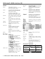
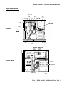
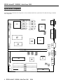
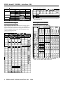
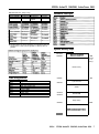
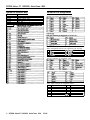
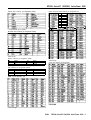
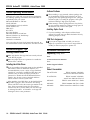
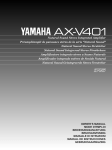
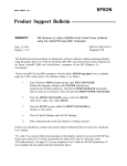
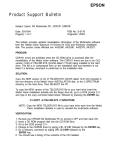
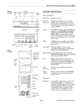
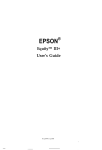
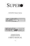
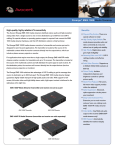
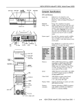
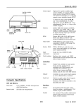
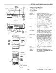
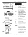
EPSON ActionPC 1500/2000, ActionTower 2000
hard disk
access light
speed light power light
I
\
drive bays
I
reset button
I
Computer Specifications
CPU and Memory
32-bit CPU
Cyrix 486SLC-33 or SLC2-50
microprocessor
System speed
Fast and slow processor speeds available;
fast is the speed of your processor and
slow is 8 MHz
Press Ctrl Alt - to select slow speed or Ctrl
Alt + to select fast speed (use the - or + on
the numeric keypad); default system
speed selectable through SETUP
diskette drive
voltage
1e / switch I
mtd
Inlet
I
AC outlet
Memory
2MB, 4MB, or 8MB RAM standard on
SIMMs; expandable to 16MB using 1MB or
4MB SIMMs; SIMMs must be tin-plated,
30-pin, 8-bit or 9-bit, fast-page mode type
with access speed of 70ns
ROM
128KB Phoenix system BIOS, video BIOS,
and SETUP program located in EPROM
on main system board
Video RAM
At least 512KB DRAM on main system
board; expandable to 1MB using four
4 x 256 DIP-type DRAM chips
Shadow RAM
Supports shadowing of system and video
BIOS ROM into RAM
Memory
relocation
Supports relocation of 128KB of memory
from A0000h to BFFFFh
Cache
1KB of internal cache on processor
Math
coprocessor
Cyrix 83S87-33 or 83S87-25
Clock/
calendar
Real-time clock, calendar, and 114 bytes of
CMOS RAM socketed on main system
board with built-in rechargeable NiCad
battery backup
PAALEL\
MOUSE
MA2
button \
-drIvebays
Controllers
3
k
Video
Cirrus Logic GD5424 high-speed super
VGA local bus on-board controller;
provides True Color support and
resolutions up to 1280 x 1024 in 16 colors
with 1MB of video RAM
Diskette
Controller on main system board supports
up to two diskette drives or one diskette
drive and one tape drive
Hard disk
IDE interface on main system board
supports up to two IDE hard disk drives
with built-in controller; BIOS provides
hard disk auto-sensing function
PARALLEL
COM1
MOUSE
Km
slots
\
AC inlet
A C o u t l e t \ voltage switch
5/9/94
EPSON ActionPC 1500/2000, ActionTower 2000 - 1
EPSON ActionPC 1500/2000, ActionTower 2000
Interfaces
Monitor
Video interface for fixed or
multi-frequency monitor built into system
board; 15-pin, D-shell connector
Parallel
One standard 8-bit parallel bidirectional
interface built into main system board;
25-pin, D-shell connector
Serial
Two RS-232C, programmable,
asynchronous interfaces built into main
system board; 9-pin, D-shell connectors
Keyboard
PS/2 compatible keyboard interface built
into main system board; 6-pin, mini DIN
connector
Mouse
PS/2 compatible mouse interface built
into main system board; 6-pin mini DIN
connector
Optional
game port
Optional 10-pin game port interface on
system board; can control joystick
functions with the addition of a port
connector
Option slots
ActionPC:
Hard disk
drives
51/4-&h or 3l&inch form factor hard disk
drive(s), up to half-height size; up to two
drives supported by the internal IDE
controller
Other devices
Half-height tape drive, CD-ROM drive,
optical drive, or other storage device;
5.25-inch or 3.5-inch (mounting frames
needed to mount a second 3.5-inch drive
in the ActionPC)
Keyboard
Detachable, two-position height; 101 or
102 sculpted keys; countrydependent
main typewriter keyboard;
numeric/cursor control keypad; four-key
cursor control keypad; 12 function keys
Mouse
Detachable, two-button, PS/2 compatible
SETUP
Program
Stored in ROM; accessible by pressing F2
during boot
Physical Characteristics
Connector card with five 16-bit, ISA
compatible expansion slots; three
full-length and two half-length
~1
ActionTower:
* With one diskette drive, without keyboard
Connector card with five full-length,
16-bit, I/O expansion slots; ISA compatible
Power Supply
Speaker
Internal
Type
200 Watt, switchable, UL/TUV listed,
fan-cooled
Mass Storage
ActionPC:
Input ranges
90 to 132 VAC
180 to 260 VAC
Maximum
outputs
+5 VDC at 20 Amps, -5 VDC at 0.5 Amp,
+12 VDC at 8 Amps, -12 VDC at 0.5 Amp
Frequency
47 to 63Hz
Cables
Two to main system board, five to mass
storage devices; for more than five
devices, Y cables can be installed on the
existing cables
Internal mount:
One 3%~inch wide, one-inch high drive
Externally accessible mounts:
One 31%~inch wide, one-inch high drive
and two 5Gnch wide, half-height drives
ActionTower:
Front internal mount:
One 3!4-inch wide, half-height drive
Rear internal mounts:
Two 3&nch wide, half-height drives or
one 3!4-inch wide, full-height drive
Externally accessible mounts:
Two 3%-inch wide, third-height drives
and two 51/4-&h wide, half-height drives
Diskette drives
Environmental Requirements
Condition
Temperature
41° to 90°F
I(cP to 32° C)
3.5-inch diskette drives, 720KB or 1.44MB
storage capacity
5.25-inch diskette drives, 360KB or 1.2MB
storage capacity
Combination diskette drives: 3.5-inch,
1.44MB and 5.25-inch, 1.2MB
2 - EPSON ActionPC 1500/2000, ActionTower 2000
I Operating Range
-4° to 140°F
) (-20° to 60° C)
Humidity
(non-condensing)
20% to 90%
10% t0 90%
Altitude
-330 to 9,900 ft
(-100 to 3.000 m)
-330 to 39,600 ft
(-100 to 12.000 m)
Maximum wet bulb
Acoustical noise
5/9/94
) Storage range
68° F (20° C)
I46.2.a
1 134° F (57° C)
I
1 N/A
I
EPSON ActionPC 1500/2000, ActionTower 2000
Major Subassemblies
The following diagrams illustrate the major subassemblies in
option card
connector
board
the
ActionPC and ActionTower systems.
J10-J12
power
video
ActionPC
memory
sockets
coprocessor
so&et
I
J15
/
drive mounting
bracket
\
drive bays
microprocessor
option card
\ connector
board
ActionTower
- herd disk drive
mounting bracket
drive bays
SIMM sockets
poker
supply
5/9/94
EPSON ActionPC 1500/2000, ActionTower 2000 - 3
EPSON ActionPC 1500/2000, ActionTower 2000
System Board Components
The diagram below illustrates the components on the ActionPC/ActionTower system board. The table following it describes
these components.
CN4
U24
U3
p-j UIO
c
I-d
CN5
U4
1
I
I
I
U23
4I
El
U11
1
L-l
U2
5/9/94
CN1
c
CN11
4 - EPSON ActionPC 1500/2000, ActionTower 2000
1
EPSON ActionPC 1500/2000, ActionTower 2000
System bad components
Socket
U2, U11
U3
U4
U5, U6, U7, U8
U10
U13, U14, U15.
Jumper settings (continued)
Component
Super l/O controller (UMC82C863,865); supports up to
two diskette drives, two serial ports. and one parallel Fort
Cirrus GD5424 video controller; local bus VGA with
TrueColor support
ALI M1217 system and memory controller
Video DRAM
Cyrix 486SLC-33/SLC2-50 processor
Socketed video DRAM
Jumper Jumper
number setting Function
1-2*
J14
Enables the IDE hard disk drive controller
2-3
Disables the IDE hard disk drive controller
1-4
J15
Selects external battery
2-3 l
Selects the system board battery
3-4
Discharges CMOS memory (this resets the SETUP
values to their factory defaults)
J16
1-2*
Enables the IDE hard disk drive controller
2-3
Disables the IDE hard disk drive controller
* Factory setting
** MS-DOS automatically reassigns parallel and serial ports. Check the
MS-DOS manual for more information.
CN1
CN2
1 PS/2 Type mouse connector; 6-pin, mini-DIN
1 PS/2 type keyboard connector; 6-pin. mini-DIN
1 Video connector; 15-pin, D-shell, high density
Built-in VGA jumper settings
Built-in VGA
Enable
Disable
I
J1
1-2*
Off
J2
1-2*
Off
*Factory setting
SIMM Installation
CN12
CN13
CN14
CN18
CN18
CN19
S1
RAM1,2,3,4
OSC1
I BAT1
1 Key-lock and power LED connector
! Speaker connector; 4-pin header
Turbo switch connector, 2-pin header
Hard disk drive connector; 40-pin header
Hard disk drive, TURBO, and power LED connector:
6-pin header
Diskette drive connector; 34-pin header
ISA 120-pin slot connector
SIMM sockets; two banks of two sockets each
Oscillator
I Battery
Jumper Settings
The following table lists the jumpers that can be changed;
other jumpers are for factory use only.
Your computer comes with 2MB, 4MB, or 8MB of memory on
memory mod&s-also called SIMMs (single inline memory
modules). By installing additional SIMMs, you can increase
the amount of memory in your computer up to 16MB.
There are four SIMM sockets on the main system board, and
each can contain one SIMM. You can use 1MB and 4MB
SIMMs.
I
The following table shows the possible SIMM configurations;
do not install memory in any other configuration. The label
on the system board for each SIMM socket (RAM1 through
RAM4) identifies the bank of sockets where you should install
SIMMS.
Possible SIMM configurations
1 BANK 0 (RAM1 and
RAM2)
1MB
1MB
4MB
4MB
umper settings
1 BANK 1 (RAM3 and
RAM4)
X
1MB
X
4MB
I
1
Total memory
2MB
4MB
8Ms
18MB
Video Memory
The computer may come with 512KB or 1MB of video
memory. You can increase the video memory to 1MB by
installing four video DRAM DIP (Dual Inline Package) chips
(44256), 70ns.
For the memory to work properly, you must install one chip
in each socket.
Enables diskette drive con
5/9/94
EPSON ActionPC 1500/2000, ActionTower 2000 - 5
EPSON ActionPC 1500/2000, ActionTower 2000
Resolutions and colors
1 Memory
Resolution I requirements
640X480
512KB
1MB
1MB
Color
256
16.7M
(True color)
256
3 2 K / 64K
16
256
1 16
800x600
512KB
1MB
1024x768
512KB
( 1MB
1280 x 1024 1 1MB
Hard disk drive types (continued)
19ukw
I
I
I
I
1 Refresh
1 rates(Hz)
Remarks
60/72
8 bits/pixel
60/72
18 bits/pixel
60/72
24 bits/pixel
8 bits/pixel
158/80/72
18 bits/pixel
43.5/60/70/72 4 bits/pixel
I43.5SWW2 8 bits/pixel
148.5
~4blts@&el
ILmdna
Iwn
I
Actual formatted size may be slightly different from size on drive label; you
cannot change this value.
]
Hard Disk Drive Types
Drive Option Information
Your computer comes with a hard disk auto-sensing feature.
When you select AUTO DETECT 1 or 2 for your hard disk
type in SETUP, the system detects the type of hard disk drive
you have installed and fills in the drive information using
values in the following table.
Hard disk drive options for I-inch IDE drives
Corn@
l
I
Hard disk drive types
BWWB)
12
I
Cqlhdm
I
Hndr
16.&ri-
Lmdng
zum
hck
61
116
im
809
78
Ia4
4
6
1,
46
39
17
2c4
112
II024
112
lam
Ii5
134
117
I
1655
llolO
17
(6
117
155
16.56
18?
wo
pmmp
0
0
DOB
762
1
Rlwnms
c?30064E
oP3mw
.I
I
Select 1 or none for the precomp value. If neither of these options are
available, select the maximum available precomp value.
6 - EPSON ActionPC 1500/2000, ActionTower 2000
5/9/94
EPSON ActionPC 1500/2000, ActionTower 2000
IDE hard disk drive jumper
Model number
Conner CP30084E
Conner CP30104H
Conner CP30174E
I
settings
Single drive
Master drive
C/D jumpered C/D jumpered
C/D jumpered
C/D, DSP
1 jumpered
Slave drive
No jumpers
Hardware Interrupts
No jumpers
1 C/D jumpered 1 C/D jumpered
AC2340
CS (cable selection) can also be jumpered for any configuration. When CS is
used, the drive is a master it pin 28 is grounded or a slave If pin 28 is not
grounded.
System Memory Map
000FFFFFFh
16MB
(maximum
000FF0000h
system
memory)
Extended memory
DMA Assignments
7
Level
DMA0
DMA1
DMA2
DMA3
DMA4
DMA5
DMA6
DMA7
1MB
00100000h
System BIOS ROM
Assigned device
Available (8-bit)
Available (8-bit)
Diskette drive controller (8-bit)
Available (8-bit)
Cascade for DMA2
Available (16-bit)
Available (16-bit)
Available (16-bit)
000F0000h
Available
000C8000h
VGA BIOS ROM
000C0000h
Display memory
000A0000h
5/9/94
640KB
EPSON ActionPC 1500/2000, ActionTower 2000 - 7
EPSON Action PC 1500/2000, ActionTower 2000
System l/O Address Map
Connector Pin Assignments
Hex address
000-01F
020-03F
022-024
040-05F
060-06F
070 - 07F (CM
080
0A0
Parallel port connector pin assignments (CN5)
Assigned device
DMA controller 1,8237
lnterrupt controller 1,8259
All M1217 configuration register
Timer, 8254
1 Keyboard and mouse controller, 8042
Mouse and keyboard connector pin assignments (CN1 and CN2)
Pin I Signal
IData
1
2
INC
3 1 CXmund
IPIn
I4
I5
it3
lSlgnal
lvcc
Iolcck
[NC
VGA port connector pin assignments (CN4)
Game port connector pin assignments (CN8)
~1
Power supply connector pin assignments (CN11)
Pin
1
2
3
4
6
8 - EPSON ActionPC 1500/2000, ActionTower 2000
5/9/94
Signal
Power good
+5VDC
+12 VDC
-12VDC
1 Ground
Pin
7
8
9
10
112
Signal
Ground
Ground
-5VDC
+5VDC
1 +5VDC
1
EPSON ActionPC 1500/2000, ActionTower 2000
Diskette drive connector pin assignments (CN19)
l
Option card riser board connector pin assignments (S1)
IA9 ISD3
A10 1 SD2
All odd-numbered pins are grounds
Pin
A31
A32
A33
A34
A35
A36
A37
A38
A39
Signal
SA3
SA2
SA1
SA0
Ground
Ground
+5VDC
SBHE*
LA23
IkK, Ia2
IB9 Iwia2
lBl0 I12VDC
1B3QllCCSlS’
]
Hard disk drive connector pin assignments (CN16)
*Active low logic
Speaker connector pin assignments (CN13)
Pin
1
2
Signal
+5VCD
NC
Pin
3
4
Signal
NC
Speak
*Active low logic
Option slot connector pin assignments
LED connector pin assignments (CN18)
Pin
1
2
3
Signal
HDD LED (+)
HDD LED (-)
Turbo LED (+)
SlMM sockets
l
Pin
4
5
6
Signal
Turbo LED (-)
Power LED (+)
Power LED (-)
(RAM1,2,3,4)
Active low logic
5/9/94
EPSON ActionPC 1500/2000, ActionTower 2000 - 9
EPSON ActionPC 1500/2000, ActionTower 2000
Tested Operating Environments
Although your system will run most software applications,
the following operating environments have been tested for
compatibility with your system.
Microsoft MS-DOS 3.1 and later
Novell DR DOS
Novell NetWare* 2.2,3.12, and 4.01
Novell NetWare Lite
IBM OS/2
SCO UN-IX
SCO Open Desktop
Microsoft Windows 3.0 and later
Microsoft Windows for WorkGroups
Microsoft Windows NT
Software Problems
P When installing a copy-protected software package, first
try the installation at high speed. If this does not work
properly, select low speed by pressing Ctrl Alt - (using the
numeric keypad). Try loading the program at low speed
and then switching to high speed, if possible.
c3 When running a software package that uses a key disk as
its copy-protection method, try loading it at high speed. If
this does not work, load it at low speed.
Installing Option Cards
Cl If you are installing a video adapter card that doesn’t
support VGA, make sure you disable the built-in VGA by
removing jumpers J1 and J2.
*Certified as workstation
COM Port Assignment
Your system has also been Novell tested and approved. As
new environments become available, these also will be tested.
0 If you want to assign COM1 as COM3, you must set
jumper J7 to position 2-3. If you want to assign COM2 as
COM4, you must set jumper J9 to position 2-3.
Installation/Support Tips
Installing Diskette Drives
Q Make sure that the drive type has been correctly selected
in the SETUP program.
0 Make sure jumper J13 is set to position 1-2 to enable the
diskette drive controller.
Installing Hard Disk Drives
Information Reference List
Engineering
Change Notices
None.
Technical Information Bulletins
None.
Product Support Bulletins
If you are installing a drive that cannot use the embedded
IDE interface, such as an ESDI hard disk drive, it is
recommended that you use a 16-bit, AT-type hard disk
controller. If you install a non-IDE hard disk drive and
controller card, you must set jumpers J14 and J16 to
position 2-3 to disable the built-in IDE hard disk drive
interface. Also be sure to remove the hard disk drive
ribbon connector from the system board.
None.
When installing a hard disk drive, see the hard disk drive
type tables on pages 6 and 7 and use the auto-sensing
feature in SETUP to select the correct type number for the
drive. If the auto-sensing feature does not produce a
match for the drive, you can define your own drive type
by selecting User Def 1 or User Def 2 as the type and
entering the drive’s exact parameters.
400311100
EPSON Action 2000 User’s Guide
400311200
EPSON ActionPC 1500 User’s Guide
400311400
EPSON ActionTower 2000 User’s Guide
Related Documentation
TM-ACTPC1520
EPSON ActionpC 1500/2000,
ActionTower 2000 Service Manual
PL-ACTPC1520
EPSON ActionPC 1500/2000,
ActionTower 2000 Parts Price List
10 - EPSON ActionPC 1500/2000, ActionTower 2000 5/9/94