1
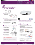
Installation and Assembly:
Advanced Projector Ceiling Mount with Precision Gear
Model: ELPMBPRG
R
Distributed by:
Epson America, Inc.
3840 Kilroy Airport Way
Long Beach, CA 90806
www.epson.com
This product is UL Listed. It must be
installed by a qualified professional
installer.
Maximum UL Load Capacity: 50 lb (22.7 kg)
Manufactured by Peerless Industries, Inc.
3215 W. North Ave. • Melrose Park, IL 60160 • (800) 865-2112 or (708) 865-8870 • Fax: (708) 865-2941 • www.peerlessmounts.com
ISSUED: 04-01-08 SHEET #: 055-9254-2
NOTE: Read entire instruction sheet before you start installation and assembly.
WARNING
• Do not begin to install your Peerless product until you have read and understood the instructions and warnings contained in this Installation Sheet. If you have any questions regarding any of the instructions or warnings, call Peerless
customer care at 1-800-729-0307.
• This product should only be installed by someone of good mechanical aptitude, has experience with basic building
construction, and fully understands these instructions.
• Make sure that the supporting surface will safely support the combined load of the equipment and all attached hardware and components.
• Never exceed the maximum UL load capacity.
• Always use an assistant or mechanical lifting equipment to safely lift and position equipment.
• This product is intended for indoor use only. Use of this product outdoors could lead to product failure and personal
injury.
• Tighten screws firmly, but do not overtighten. Overtightening can damage the items, greatly reducing their holding
power. See suggested torque values where applicable within these instructions.
Tools Needed for Assembly
•
•
•
•
•
•
stud finder ("edge to edge" stud finder is recommended)
phillips screwdriver
drill
1/4" bit for concrete surface
5/32" bit for wood joist
3/8" (10 mm) socket or open end wrench
Table of Contents
Parts List .............................................................................................................................................................................. 3
Installation to Extension Column ........................................................................................................................................... 4
Installation To Wood Joist Ceilings ....................................................................................................................................... 5
Installation to Concrete Ceilings ............................................................................................................................................ 6
Installing Plates to Projector ................................................................................................................................................. 7
Adjusting Connection Block and Installing Plates to Projector ........................................................................................... 7-8
Installing Connection Block to Projector Mount Assembly .................................................................................................... 9
Cable Management ............................................................................................................................................................. 10
Projector Alignment ............................................................................................................................................................ 11
Accessories and Warranty Information ............................................................................................................................... 12
2 of 12
Visit the Peerless Web Site at www.peerlessmounts.com
ISSUED: 04-01-08 SHEET #: 055-9254-2
For Technical Support Contact Peerless Mounts at 1-800-729-0307 or 708-865-8870.
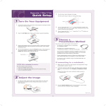
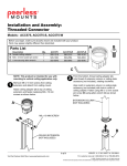
Before you start check the parts list to ensure all of the parts shown are included.
A
Parts List
A
B
C
D
E
F
G
H
I
J
K
L
M
Description
projector mount assembly
adapter plate
side plate
M4 x 20 mm socket pin serrated washer head screw
M5 x 20 mm socket pin serrated washer head screw
3/8" spacer
M4 x 6 mm socket pin serrated washer head screw
#10-32 x 3/8'' socket pin serrated washer head screw
10-32 x 1/4'' socket pin screw with lock
4 mm security allen wrench
washer
#14 x 2.5'' wood screw
Alligator® anchor
Qty.
1
1
2
4
4
4
6
2
1
1
2
2
2
Part Number
055-2804
055-2806
055-2807
510-2163
510-2065
590-2150
510-2059
520-2151
520-2196
560-9646
540-1078
5S1-015-C04
590-0097
B
C
NOTE: Actual parts may appear slightly different than illustrated.
D
E
H
G
F
I
(Pre-assembled to "B")
J
K
L
M
3 of 12
Visit the Peerless Web Site at www.peerlessmounts.com
ISSUED: 04-01-08 SHEET #: 055-9254-2
For Technical Support Contact Peerless Mounts at 1-800-729-0307 or 708-865-8870.
Installation to Extension Column
1
NOTE: Refer to accompanying instructions for ELPMBP01, ELPMBP02, ELPMBP03 or CMJ and ACC Series Ceiling
Mounts (sold separately) for installing these models to ceiling.
Screw projector mount assembly (A) onto extension column as shown in figure 1.1.
NOTE: Swivel stop screw is used to jam against threads of extension column or flush mount tube to prevent any
excess movement of projector mount assembly (A) as shown in detail 1. Do not overtighten screw; overtightening
screw will damage threads making it difficult to separate products.
Skip to step 2.
Not Shown: UL Listed ELPMBP01, ELPMBP02, ELPMBP03 or UL
Listed CMJ and ACC Series Ceiling Mounts (Sold Separately).
EXTENSION COLUMN
(UL Listed ELPMBC01 or UL Listed
EXT and ADJ Series)
(Sold Separately)
A
SWIVEL STOP
SCREW
ARROW
INDICATES
FRONT OF
MOUNT
fig. 1.1
A
DETAIL 1
A
fig. 1.2
4 of 12
Visit the Peerless Web Site at www.peerlessmounts.com
ISSUED: 04-01-08 SHEET #: 055-9254-2
For Technical Support Contact Peerless Mounts at 1-800-729-0307 or 708-865-8870.
Installation To Wood Joist Ceilings
WARNING
• Installer must verify that the supporting surface will safely support the combined load of the equipment and all attached
hardware and components.
• Tighten wood screws so that projector mount assembly is firmly attached, but do not overtighten. Overtightening can
damage the screws, greatly reducing their holding power.
• Never tighten in excess of 80 in. • lb (9 N.M.).
• Make sure that mounting screws are anchored into the center of the stud. The use of an "edge to edge" stud finder is
highly recommended.
• Hardware provided is for attachment of mount through standard thickness drywall or plaster into wood studs. Installers
are responsible to provide hardware for other types of mounting situations (not UL approved).
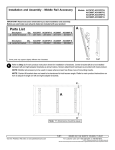
1
Place projector mount assembly (A) on ceiling as a template and mark the center of the two mounting holes. Make
sure that the mounting holes are in the center of the wood joist. Drill two 5/32" (4 mm) dia. holes to a minimum
depth of 2.5" (64 mm). Attach projector mount assembly (A) with two #14 x 2.5" (6 mm x 65 mm) wood screws (L)
and two flat washers (K) as shown in figure 1.3 or figure 1.4 depending on joist orientation.
NOTE: Mounting slots on projector mount assembly allow for 30° (±15°) of swivel adjustment before fully securing
wood screws.
Tighten wood screws (L) using 3/8" (10 mm) socket or open end wrench or phillips screwdriver until projector mount
assembly (A) is firmly attached.
Skip to step 2.
WOOD JOIST
ACCESS SLOT FOR
OPEN END WRENCH
ALLOWS TIGHTENING
OF WOOD SCREW (L)
WOOD JOIST
ARROW
INDICATES
FRONT OF
MOUNT
A
A
ARROW
INDICATES
FRONT OF
MOUNT
K
K
L
L
fig. 1.4
fig. 1.3
5 of 12
Visit the Peerless Web Site at www.peerlessmounts.com
ISSUED: 04-01-08 SHEET #: 055-9254-2
For Technical Support Contact Peerless Mounts at 1-800-729-0307 or 708-865-8870.
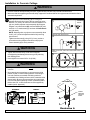
Installation to Concrete Ceilings
WARNING
• Concrete must be 2000 psi density minimum. Lighter density concrete may not hold concrete anchor.
• Make sure that the supporting surface will safely support the combined load of the equipment and all attached hardware and components.
1
Place projector mount assembly (A) on ceiling as a
template and mark the center of the two mounting holes.
Drill two 1/4" (6 mm) dia. holes to a minimum depth of 2.5"
(64 mm). Attach projector mount assembly (A) using two
Alligator® concrete anchors (M), two flat washers (K), and
two #14 x 2.5" wood screws (L) as shown in Illustration A
and 1, 2 and 3).
NOTE: Mounting slots on projector mount assembly allow
for 30° (±15°) of swivel adjustment before fully securing
wood screws.
Tighten wood screws (L) using 3/8" (10 mm) socket or
open end wrench or phillips screwdriver until projector
mount assembly (A) is firmly attached.
1
CONCRETE
CEILING
M
Drill hole and insert anchor
2
A
L
WARNING
• Tighten wood screws firmly, but do not overtighten.
Overtightening can damage the screws, greatly reducing
their holding power.
M
K
Place mount over anchor and secure with screw and
washer
3
L
• Never tighten in excess of 80 in • lb (9 N.M.).
WARNING
• Always attach concrete anchors directly to load-bearing
concrete.
After repeating step one tighten all fasteners
• Never attach concrete anchors to concrete covered with
plaster, drywall, or other finishing material. If mounting to
concrete surfaces covered with a finishing surface is
unavoidable, the finishing surface must be counterbored as
shown below. Be sure concrete anchors do not pull away
from concrete when tightening screws. If plaster/drywall is
thicker than 5/8", custom fasteners must be supplied by
installer (not UL approved).
CUTAWAY VIEW
INCORRECT
A
CONCRETE CEILING
CORRECT
concrete
plaster/
dry wall
M
K
A
concrete
M
A
plaster/
dry wall
ARROW
INDICATES
FRONT OF
MOUNT
K
L
Illustration A
6 of 12
Visit the Peerless Web Site at www.peerlessmounts.com
ISSUED: 04-01-08 SHEET #: 055-9254-2
For Technical Support Contact Peerless Mounts at 1-800-729-0307 or 708-865-8870.
Installing Plates to Projector
CAUTION
• All spacers shall be used where indicated. Not using spacers can cause damage to projector.
• It is the responsibility of the installer to ensure that the projector is properly ventilated.
NOTE: For all POWERLITE models, the manufacturer's product weight must be reviewed to ensure that the weight does not
exceed 50 lbs.
Adapter Plate: POWERLITE 1700c, 1705c, 1710c,
1715c, 1810p, 1815p, 1825, S5, 77c, 83+, 822+
2
3-Plate Horizontal Configuration: POWERLITE
6100i, 6110i, 7900p
Use adapter plate (B) as shown. Continue to step 3.
2
Attach adapter plate (B) to side plates (C) using six
M4 x 6 mm socket pin screws (G).
G
B
B
C
3-Plate Vertical Configuration: POWERLITE 8300i
2
Loosen two #10-32 x 3/8" serrated washer head socket pin
screws (H) on adapter plate (B) and connection block as shown in
bottom detail 1. Rotate connection block to 90° as shown in fig. 2.1.
Securely retighten #10-32 x 3/8" serrated washer head socket pin
screws (H).
H
2-1
Attach adapter plate (B) to side
plates (C) using six M4 x 6 mm
socket pin screws (G)
G
B
B
CONNECTION BLOCK
BOTTOM
DETAIL 1
B
C
fig. 2.1
7 of 12
Visit the Peerless Web Site at www.peerlessmounts.com
ISSUED: 04-01-08 SHEET #: 055-9254-2
For Technical Support Contact Peerless Mounts at 1-800-729-0307 or 708-865-8870.
3
NOTE: Shoulder indicates back of adapter plate (B)
Flip projector upside down. Find your projector model from the hole patterns listed below. Using the holes indicated on
the corresponding hole pattern diagram, attach adapter plate (B) to projector using the appropriate number of
M4 x 20 mm socket pin serrated washer head screws (D) and spacers (F). NOTE: For POWERLITE model 8300i, use
M5 x 20 mm socket pin serrated washer head screws (E) in place of screws (D).
NOTE: Retaining spacers go between adapter plate and projector.
C
SCREW
NOTE: SHOULDER
INDICATES THE BACK OF
ADAPTER PLATE (B)
B
SPACER
FRONT
Hole Patterns
A. POWERLITE 1700c, 1705c, 1710c,
1715c
B. POWERLITE S5, 77c, 83+, 400W,
822+, 1810p, 1815p, 1825
FRONT
C. POWERLITE 6100i, 6110i
FRONT
D. POWERLITE 7900p
E. POWERLITE 8300i
FRONT
FRONT
8 of 12
Visit the Peerless Web Site at www.peerlessmounts.com
FRONT
ISSUED: 04-01-08 SHEET #: 055-9254-2
For Technical Support Contact Peerless Mounts at 1-800-729-0307 or 708-865-8870.
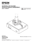
Installing Connection Block to Projector Mount Assembly
WARNING
• Always use an assistant or mechanical lifting equipment to safely lift and position the projector.
4
Slide connection block with projector into projector mount assembly (A) as shown. Tighten captive screw to secure
projector to projector mount assembly (A).
A
FRONT OF MOUNT
CONNECTION BLOCK
ARROW
INDICATES
FRONT OF
MOUNT
CAPTIVE
SCREW
5
IMPORTANT: For security installations, insert one #10-32 x 1/4" socket pin screw (I) through projector mount
assembly (A) and into connection block as shown.
I
A
CONNECTION BLOCK
9 of 12
Visit the Peerless Web Site at www.peerlessmounts.com
ISSUED: 04-01-08 SHEET #: 055-9254-2
For Technical Support Contact Peerless Mounts at 1-800-729-0307 or 708-865-8870.
Cable Management
6
To make an opening to route cables through
projector mount assembly, adjust projector mount
assembly to full upward tilt position and maximum
left or right roll position by turning knobs for
adjustments as shown in figure 6.1.
KNOB FOR ROLL
ADJUSTMENT
KNOB FOR TILT
ADJUSTMENT
NOTE: Be certain tamper resistant screws are
not engaged before making adjustments (see
step 7-1).
Route cables through top of extension column as
shown in figure 6.2 and figure 6.3.
NOTE: A method for assisting cables through
extension column may be required (example: string
tied to connector to help pull through extension
column).
fig. 6.1
Route cables through projector mount assembly as
shown in figure 6.4 and connect to projector.
OPENING FOR
ROUTING CABLES
fig. 6.3
CABLES WITH COMBINATION
OF VGA CONNECTOR
AND RCA PLUGS
BEND WIRES OF RCA
PLUGS IN OPPOSITE
DIRECTION
EXTENSION
COLUMN
MAXIMUM DIMENSIONS
EXTENSION COLUMN
WILL ALLOW
HEIGHT DIMENSION
WILL VARY DEPENDING
ON WIDTH DIMENSION
MAXIMUM
WIDTH
1-9/16"
(40 mm)
ROUTE
CONNECTOR
THROUGH
FIRST
DO NOT
CRIMP
WIRES
fig. 6.2
fig. 6.4
10 of 12
Visit the Peerless Web Site at www.peerlessmounts.com
ISSUED: 04-01-08 SHEET #: 055-9254-2
For Technical Support Contact Peerless Mounts at 1-800-729-0307 or 708-865-8870.
Projector Alignment
7
To adjust yaw (swivel) for extension column installation: Loosen screw on projector mount assembly (A)
indicated below until projector mount can be rotated. Rotate mount to desired position and retighten screw.
To adjust pitch (forward and backward tilt): Turn knob on back of mount as shown below. Pull knob out and turn
by hand for easy adjustment or insert #2 phillips screwdriver in end of knob and turn.
To adjust roll (side to side tilt): Turn knob on side of mount as shown below. Pull knob out and turn by hand for
easy adjustment or insert #2 phillips screwdriver in end of knob and turn.
A
ARROW INDICATES
FRONT OF MOUNT
KNOB FOR PITCH
ADJUSTMENT
BACK OF MOUNT
KNOB FOR ROLL
ADJUSTMENT
SCREW FOR SWIVEL STOP
7-1
To prevent tampering with the pitch and roll adjustments: Tighten the two tamper resistant security screws
on the projector mount assembly using 4 mm security allen wrench (J) to lock the pitch and roll adjustments as
shown below.
NOTE: Tighten screws firmly, but do not overtighten. Overtightening can damage the mount.
CAUTION
• Do not adjust pitch or roll while tamper resistant security screws are fully engaged.
• Loosen the two tamper resistant security screws one complete turn before adjusting the projector mount assembly or
damage may occur.
TO LOCK ROLL TIGHTEN
TAMPER RESISTANT
SECURITY SCREW
FRONT VIEW
SIDE VIEW
11 of 12
Visit the Peerless Web Site at www.peerlessmounts.com
TO LOCK PITCH TIGHTEN
TAMPER RESISTANT
SECURITY SCREW
ISSUED: 04-01-08 SHEET #: 055-9254-2
For Technical Support Contact Peerless Mounts at 1-800-729-0307 or 708-865-8870.
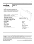
Accessories
NOTE: All accessories are available for purchase through Epson (www.epson.com)
ELPMBP02
False Ceiling Plate Kit
ELPMBP01
Adjustable Suspended Ceiling Channel Kit
• Mounts above 2' x 2' or 2' x 4' ceiling tile
to structural ceiling with tie wires
• Includes tie wire supports and flush mount
tube
• 1 ½" - 11.5" NPT fitting for attachment of
adjustable extension column
• Two knockout panels for electrical outlet
boxes
• 13.9" continuous, uninterrupted projector adjustment
• Escutcheon ring included for a clean finish
• Max weight load: 60 lb (27 kg.)
• Color: White
• Replaces a 2' x 2' ceiling tile and mounts to
structural ceiling with tie wires
• Two-piece design offers five different points
for mount attachment
• Includes tie wire supports and flush mount
tube
• 1 ½" - 11.5" NPT fitting for attachment of
adjustable extension column
• Two knockout panels for electrical outlet boxes
• Max weight load: 50 lb (23 kg.)
• Color: White
R
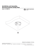
ELPMBP03
Structural Round Ceiling Plate
R
ELPMBC01
Adjustable Extension Column (Pipe) 8" - 11"
• Mounts to wood joist or structural concrete ceiling
• Features cable management access hole
• 1 ½" - 11.5" NPT fitting for attachment of
adjustable extension column
• Max weight load: 150 lb (68 kg.)
• Color: White
• 8" - 11" adjustable extension in 1" increments
• Specially designed to allow internal cable
management
• 1 ½" - 11.5" NPT pipe threaded on both ends
• Notched ends for use with set screw to provide
safety and security
• Color: White
R
R
LIMITED FIVE-YEAR WARRANTY
3HHUOHVV,QGXVWULHV,QFHVWDEOLVKHVDZDUUDQW\SHULRGRIÀYH\HDUVIRUSURGXFWVPDQXIDFWXUHGRUVXSSOLHGE\3HHUOHVV7KLVSHULRGFRPPHQFHVIURPWKHGDWH
RIVDOHRIWKHSURGXFWWRWKHRULJLQDOFRQVXPHUEXWZLOOLQQRFDVHODVWIRUPRUHWKDQVL[\HDUVDIWHUWKHGDWHRIWKHSURGXFWҋVPDQXIDFWXUH'XULQJWKHZDUUDQW\
SHULRGVXFKSURGXFWVZLOOEHIUHHIURPGHIHFWVLQPDWHULDODQGZRUNPDQVKLSSURYLGHGWKH\DUHLQVWDOOHGDQGXVHGLQFRPSOLDQFHZLWKWKHLQVWUXFWLRQVHVWDEOLVKHGE\
3HHUOHVV,QGXVWULHV,QF6XEMHFWWRDSSOLFDEOHOHJDOUHTXLUHPHQWVGXULQJWKHZDUUDQW\SHULRG3HHUOHVVZLOOUHSDLURUUHSODFHRUUHIXQGWKHSXUFKDVHSULFHRIDQ\
VXFKSURGXFWZKLFKIDLOVWRFRQIRUPZLWKWKLVZDUUDQW\
$Q\RWKHUZDUUDQWLHVSUHVFULEHGE\WKHODZZKLFKPD\DSSO\ZLWKUHVSHFWWRVXFKSURGXFWVDOVRDUHOLPLWHGLQGXUDWLRQWRWKHZDUUDQW\SHULRGVSHFLÀHGLQWKLV/LPLWHG
)LYH<HDU:DUUDQW\
7KLVZDUUDQW\GRHVQRWFRYHUGDPDJHFDXVHGE\DVHUYLFHRUUHSDLUVE\WKHFXVWRPHURUDSHUVRQZKRLVQRWDXWKRUL]HGIRUVXFKVHUYLFHRUUHSDLUVE\3HHUOHVV
,QGXVWULHV,QFEWKHIDLOXUHWRXWLOL]HSURSHUSDFNLQJZKHQUHWXUQLQJWKHSURGXFWFLQFRUUHFWLQVWDOODWLRQRUWKHIDLOXUHWRIROORZ3HHUOHVVҋLQVWUXFWLRQVRUZDUQLQJV
ZKHQLQVWDOOLQJXVLQJRUVWRULQJWKHSURGXFWRUGPLVXVHRUDFFLGHQWLQWUDQVLWRURWKHUZLVHLQFOXGLQJLQFDVHVRIWKLUGSDUW\DFWLRQVDQGIRUFHPDMHXUH
,QQRHYHQWVKDOO3HHUOHVVEHOLDEOHIRULQFLGHQWDORUFRQVHTXHQWLDOGDPDJHVRUGDPDJHVDULVLQJIURPWKHWKHIWRIDQ\SURGXFWZKHWKHURUQRWVHFXUHGE\DVHFXULW\
GHYLFHZKLFKPD\EHLQFOXGHGZLWKWKHSURGXFW
7KLV/LPLWHG)LYH<HDU:DUUDQW\LVLQOLHXRIDOORWKHUZDUUDQWLHVH[SUHVVHGRULPSOLHGDQGLVWKHVROHUHPHG\ZLWKUHVSHFWWRSURGXFWGHIHFWV1RUHWDLOHUGHDOHU
GLVWULEXWRULQVWDOOHURURWKHUSHUVRQLVDXWKRUL]HGWRPRGLI\RUH[WHQGWKLVZDUUDQW\RULPSRVHDQ\REOLJDWLRQRQ3HHUOHVVLQFRQQHFWLRQZLWKWKHVDOHRIDQ\SURGXFW
PDQXIDFWXUHGRUVXSSOLHGE\3HHUOHVV
7KLVZDUUDQW\JLYHVVSHFLÀFOHJDOULJKWVDQG\RXPD\DOVRKDYHRWKHUULJKWVSURYLGHGE\WKHQDWLRQDOOHJLVODWLRQRIWKHFRXQWU\LQZKLFK\RXSXUFKDVHGVXFKSURGXFW
www.peerlessmounts.com
© 2007 Peerless Industries, Inc.
ISSUED 03/17/06 LIT-0190E
12 of 12
Visit the Peerless Web Site at www.peerlessmounts.com
ISSUED: 04-01-08 SHEET #: 055-9254-2
For Technical Support Contact Peerless Mounts at 1-800-729-0307 or 708-865-8870.
© 2008, Peerless Industries, Inc. All rights reserved.
Epson is a registered trademark and Epson Exceed Your Vision is a trademark of Seiko Epson Corporation.
All other brand and product names are trademarks or registered trademarks of their respective owners.