1
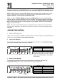
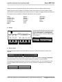
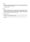
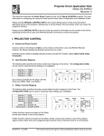
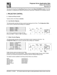
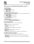
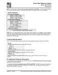
Quick Start Reference Sheet
Epson EMP-7800
Revision D
NOTE: This document is intended only as a quick reference for installation – please read the SP
Controls Application Note for a complete description of this projector driver prior to installation.
I. Driver Features
1. Input Selection Mapping
Selection 1:
Selection 2:
Selection 3:
Selection 4:
VIDEO (RCA)
S-VIDEO
YPbPr (BNC)
COMPUTER (VGA)
2. Hidden Function Mapping (Default Configuration)
Using the ON button as a shift key, press the following buttons to access the specified projector features.
Selection 1:
Selection 2:
Selection 3:
Selection 4:
Off:
Volume Up:
Volume Down:
ESC
ENTER
ADJUST LEFT
ADJUST RIGHT
MENU
ADJUST UP
ADJUST DOWN
3. Other Driver Features
Power Status Feedback Method
Control Wiring:
RS-232 Power Polling
RS-232 Only
II. Wiring Specifications
Although this driver does not use IR, SP Controls strongly recommends wiring for RS-232 and IR. Under
certain conditions it may be necessary to control this projector through IR – see the Special Control Note
in the Application Note below for more information.
NOTE: For a wiring diagram, please see the SP Controls Application Note.
Wire the Panel RS-232 port to a female DB9 as follows:
TX to 2
RX to 3
GND to 5
Connect this female DB9 to the projector port labeled CONTROL (RS-232C).
Wire the Panel IR/Serial port to a female 1/8" Mini as follows:
IR/SER to tip
GND to ring
Connect to the included IR Emitter and attach the emitter bud to the rear projector IR window. Note
that
the projector does not consistently respond when the IR emitter is attached to the front IR window.
DR-EPS19 – 3/29/04
SP Controls reserves the right to modify specifications without notice at any time.
SmartPanel Projector Driver Application Note
Epson EMP-7800
III. Additional Projector Information
NOTE: For use with this driver, the Epson EMP-7800 should be running projector firmware version 2.05
or higher. For information on how to check your projector firmware version and instructions on how to
upgrade if necessary, see the Projector Firmware Note in the Application Note below.
NOTE: The Epson STANDBY MODE must be set to NETWORK ON in the projector ADVANCED1
onscreen menu or the projector may stop responding to RS-232 commands. See the Special Control
Note 1 in the Application Note below for more information.
NOTE: Several additional projector settings must be correctly configured for the Epson EMP-7800 to
work with the SmartPanel. See Special Control Note 2 in the Application Note below for more information.
•
•
•
•
STARTUP SCREEN should be set to OFF in the ADVANCED1 Menu.
COM PORT must be set to RS-232 in the ADVANCED2 menu.
SLEEP MODE should be set to OFF in the SETTING Menu.
DISPLAY MESSAGE should be set to OFF in the SETTING Menu.
© 2004 SP Controls Inc. 601 Minnesota Suite 115, San Francisco, CA 94107
[email protected]
Projector Driver Application Note
Epson EMP-7800
Revision D
This document describes the SmartPanel Projector Driver for the Epson EMP-7800 projector. For more
information on configuring and using the Panel see the SmartPanel Configuration and Installation Guide.
NOTE: For RS-232 control, the Epson EMP-7800 should be running projector firmware version 2.05 or
higher. For information on how to check your projector firmware version and instructions on how to
upgrade if necessary, see the Projector Firmware Note below.
NOTE: The Epson STANDBY MODE must be set to NETWORK ON in the projector ADVANCED1
onscreen menu or it may stop responding to RS-232 commands. See Special Control Note 1 in Section
II, Control Wiring below for more information. If you are unable to set STANDBY MODE to NETWORK
ON, an IR-only version (Revision C) of this projector driver is available. Contact SP Controls technical
support for more information.
NOTE: There are several additional projector configurations which are required for use of the Epson
projector with the SmartPanel. See Special Control Note 2 in Section II, Control Wiring below for more
information.
I. PROJECTOR CONTROL
A. Volume and Power Control
Volume control on the Epson is relative. Absolute volume control for the Epson is also possible with use
of SP Controls’ optional Audio Follow Video Pre-Amplifier.
B. Input Selection Mapping
The following table specifies the factory-preset input mapping for this Driver. The Configuration Utility
can be used to customize these settings your installation.
S-VIDEO
YPBPR (BNC)
VIDEO (RCA)
COMPUTER (VGA)
Projector
Volume
ON
Ready
OFF
Selection 1:
Selection 2:
Selection 3:
Selection 4:
VIDEO (RCA)
S-VIDEO
YPbPr (BNC)
COMPUTER (VGA)
Warm-up
Input choices available for the Epson with this
Driver are: Video (RCA), S-Video, Computer
(VGA), DVI, RGB-VID (BNC), YPbPr (BNC),
YCbCr (BNC).
C. Hidden Function Mapping
The following table specifies the factory preset hidden function mapping for this Driver. The
Configuration Utility can be used to customize these settings your installation.
ENTER
ADJUST
LEFT
ADJUST
RIGHT
ESC
ADJUST
UP
Projector
ON
Ready
OFF
MENU
DR-EPS19 – 3/29/04
Warm-up
ADJUST
DOWN
Volume
Selection 1:
Selection 2:
Selection 3:
Selection 4:
Off:
Volume Up:
Volume Down:
ESC
ENTER
ADJUST LEFT
ADJUST RIGHT
MENU
ADJUST UP
ADJUST DOWN
SP Controls reserves the right to modify specifications without notice at any time.
SmartPanel Projector Driver Application Note
Epson EMP-7800
Hidden functions are accessed by pressing the indicated key while the holding the On key down.
Hidden functions names are based on the Epson remote and controls on top of the projector. Adjust,
Enter and ESC controls navigate through onscreen menus. A/V Mute is a toggling Audio and Video mute.
The hidden functions available for the Epson with this Driver are as follows:
BRIGHT +
BRIGHT –
E-ZOOM +
E-ZOOM –
SYNC +
SYNC –
MENU
ADJUST LEFT
ADJUST RIGHT
ADJUST UP
ADJUST DOWN
ENTER
ESC
TRACKING +
TRACKING –
A/V MUTE
HELP
RESIZE
D. Relays
500mA MAX. CURRENT
7A
6B
6A
5B
5A
SELECTION
(EXT. SWITCHER CTRL)
3
2
4B
4
4A
3B
PWR
OFF
MOM.
3A
2B
2A
1B
1A
PWR
ON
MOM.
1
7B
RELAYS
PWR
ON
MAINT.
The following table specifies the factory preset
settings for the low-current relays found on the
rear of the SmartPanel. The Configuration
Utility can be used to customize these settings
your installation.
Relay 1
Relay 2
Relay 3
Selection
ON Maintained
ON Momentary
OFF Momentary
Momentary; not Binary
E. Other Presets
The following table specifies other default factory settings for this Driver that affect is control of the
Projector.
Power Status Feedback Method
Control Wiring Option
RS-232 Polling (see note 1)
RS-232 Only (see note 2)
All control for the Epson with this Driver is via RS-232. However, SP Controls strongly recommends
wiring the IR emitter. See Section III. Projector Firmware Note below for more information.
The following table specifies settings for the Panel’s configurable timers. For more information on the
inactivity shutdown feature and the lockout timer see the SmartPanel Configuration and Installation
Manual.
Lockout Timer
Inactivity Shutdown
42 seconds (see note 3)
Disabled
© 2004 SP Controls Inc. 601 Minnesota Suite 115, San Francisco, CA 94107
[email protected]
SmartPanel Projector Driver Application Note
Epson EMP-7800
II. CONTROL WIRING
This section specifies how RS-232 should be wired to the
Epson projector. Although this driver is RS-232-only, SP
Controls strongly recommends that you also wire IR in
case you make a decision to use Revision C of this driver,
which uses IR control. Please Section III below for more
information.
PROJECTOR CONTROL
GND
SENSE
IR/SER
+12V
CTS
IR/SERIAL
GND
RTS
TX
RX
RS232
RS-232 should be connected to the Epson control port
labeled CONTROL (RS-232C). Connection should be as
follows:
1. Wire the Panel to a female DB9 as follows:
TX to 2
RX to 3
GND to 5
5 4 3 2 1
Female DB9
1/8" Mini
Female
9 8 7 6
2.
Connect this female DB9 to the projector port labeled
CONTROL (RS-232C).
The Infrared emitter (squirt) bud should be attached to the
rear IR window. IR control does not work effectively from
the front projector IR window.
IR Emitter
(included with Panel)
Connection should be as follows:
1. Wire the Panel to a female 1/8" Mini as shown; wire
IR/SER to tip and GND to ring. Direct wiring to the IR
Emitter is not recommended as it makes removal of the
Panel for service more difficult.
2. Attach to any projector IR port using the Panel’s IR
Emitter (included with the Panel).
Note that the emitter glows red when IR is emitted so wiring
can be verified.
SPECIAL CONTROL NOTE 1:
The Epson EMP-7800 projector must be configured to
STANDBY MODE: NETWORK ON in the projector
onscreen menu ADVANCED1. If the projector STANDBY
MODE is not configured to NETWORK ON, it may stop
responding to RS-232 commands.
RS-232 to Epson Port
Control (RS-232C)
Emitter Bud to REAR
Epson IR Window
If the projector does stop responding to RS-232 control,
manually power down the Epson projector. Once the
projector cools down, unplug the projector from the outlet
and allow it 15 seconds to reset. Reapply power and the
projector should work normally.
Note: When the projector is placed in STANDBY MODE:
NETWORK ON the projector fan remains on in standby
mode. This is normal projector behavior.
© 2004 SP Controls Inc. 601 Minnesota Suite 115, San Francisco, CA 94107
[email protected]
SmartPanel Projector Driver Application Note
Epson EMP-7800
SPECIAL CONTROL NOTE 2:
Several additional projector settings must be configured for the Epson EMP-7800 to work with the
SmartPanel. Access the Epson's settings via the onscreen menu using the SmartPanel's hidden functions
or the Epson's remote control.
•
•
•
•
STARTUP SCREEN should be set to OFF in the ADVANCED1 Menu.
COM PORT must be set to RS-232 in the ADVANCED2 menu.
SLEEP MODE should be set to OFF in the SETTING Menu.
DISPLAY MESSAGE should be set to OFF in the SETTING Menu.
III. PROJECTOR FIRMWARE NOTE
This driver is known to work with Epson EMP-7800 projectors with projector firmware version 2.05 or
higher. It is possible that units running with firmware versions less than 2.05 will stop responding to RS232 control under certain conditions. Should this occur, control can be restored by powering off and
unplugging the projector, and then plugging it back in.
SP Controls strongly recommends verifying the projector firmware version during installation, and if it is
less than version 2.05, upgrading the projector firmware. The EMP-7800 firmware is flash-upgradeable in
the field with a laptop – the process is quick and simple.
In order to verify the firmware version of your projector:
1) Use the projector remote control to power on the projector.
2) When the projector is on at full brightness, press and hold the HELP button on the remote control for 57 seconds, until the service menu comes up.
3) At the bottom of the service menu, you will see three numbers listed. The first number, indicated by P:,
is a long number indicating the firmware version. The last three digits of this number indicate which
version you are running.
If the firmware version on your projector is less than 2.05, please contact Epson. For contact information,
refer to your Epson documentation.
NOTE: SP Controls also has an IR-only version of this projector driver available, which will run on any
firmware version of the Epson EMP-7800 with no difficulty.
We recommend using Revision D with RS-232 control, as it provides more robust control and 2-way
communication with the projector. If you would like the IR-only driver, or if you have any questions about
this procedure, please contact SP Controls Technical Support.
© 2004 SP Controls Inc. 601 Minnesota Suite 115, San Francisco, CA 94107
[email protected]
SmartPanel Projector Driver Application Note
Epson EMP-7800
IV. TROUBLESHOOTING
Addition tips can be found in the SmartPanel Configuration and Installation Guide.
The Panel powers the projector on, but then the Panel does not respond!
If the projector STANDBY MODE is not configured to NETWORK ON, the projector may stop
responding to RS-232 control. To restore control, the projector must be manually turned off and
unplugged. See Special Control Note 1 in Section II, Control Wiring above.
If the projector firmware version is less than 2.05, then in some circumstances the projector may stop
responding to RS-232 commands even if STANDBY MODE: NETWORK ON is set. See Section III.
Projector Firmware Note above.
The projector is not responding to Panel control!
Several menu settings must be configured for the Epson to work with the SmartPanel. See Special
Control Notes 1 and 2 in Section II above.
The Panel does not do anything at all.
When power is applied to the Panel it should run through a brief power on self-test, during which all of
the Panel lights will turn on and off in sequence. If you do not see this self-test, make sure power is
connected correctly and that polarity is correct.
The Panel keeps turning itself off even though the projector is on.
The Panel turns itself off when power polling indicates that the projector is off. Check to make sure
the RS-232 connection is correctly wired. If the Panel turns itself off after a long delay of several
minutes or more, then the Panel may be configured with the optional Automatic Shutdown Timer.
For more information, see the SmartPanel Configuration and Installation Manual.
When I try to turn the projector on, the warming indicator (red LED) blink.
The projector is in the default configured lockout state, and the Panel is waiting for its internal lockout
timer to expire; this protects the projector’s bulb. Be sure to let your client know about this behavior.
V. TECHNICAL NOTES
1.
By default, projector power is verified by polling every few seconds via the RS-232 port. Power
polling can be suspended by depressing and holding the On key; polling will be restored when the
key is released. Should the Epson power off, the Panel will detect this and power off within twenty
seconds. Should it power on, the Panel will detecting this and power on within thirty seconds.
2.
The Epson is completely controlled via RS-232; IR/Wired Remote control does not have to be wired
for this Driver. However, we always recommend wiring both RS-232 and Wired Remote/IR in case
the Driver or projector specifications change.
3.
The lockout timer specifies the amount of time allowed between sending POWER OFF and POWER
ON to the projector (the delay allows the projector bulb to cool before re-powering). This delay can
be configured using the Configuration Utility; however, adjusting the lockout timer delay is
strongly discouraged as rapid re-powering causes undue wear on the projector’s bulb., disabling
the lockout delay will cause potentially confusing Panel behavior.
VI. REVISION HISTORY
1.
2.
3.
4.
Revision A (September, 2003) Initial release – TK.
Revision B (September, 2003) Revised input selections, minor revisions – BT.
Revision C (March, 2004) IR-Only option – BT.
Revision D (March, 2004) Minor revisions addressing RS-232 port configuration requirements – BT.
© 2004 SP Controls Inc. 601 Minnesota Suite 115, San Francisco, CA 94107
[email protected]