1
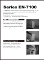
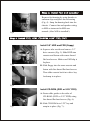
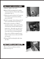
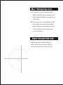
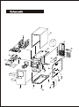
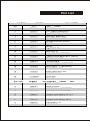
EN-7100
USER MANUAL
Series EN-7100
***Important-First please check your model number before proceeding. The user
manual is set up to correspond to the model number and installation will vary
depending on the model.
Required tools: Phillips head screwdriver, pliers
***(Photos shown may vary according to model number)
Place case on edge of table (Fig.1). With one
hand holding top of chassis, pull quickly from
the bottom of the bezel to remove it (Fig. 2).
**Note-It might require some force to remove
due to the snug fit to the chassis.
Fig:1
Fig:2
Remove screws. Place hands on sides of
top cover and thumbs firmly on chassis.
Slide top cover towards you 1" (Fig. 3).
Spread sides and lift straight up to remove.
Fig:3
Fig:4
Remove fan housing by using thumbs to
unfasten clips and place fan in housing
(Fig. 4). Snap fan housing back into the
chassis. Connect fan and speaker wiring
to M/B as instructed in M/B user
manual (After M/B is installed!).
Install 3.5" HDD and FDD (floppy)
A. Squeeze tabs on side and remove 3.5"
drive cassette (Fig. 5). Slide HDD into
cassette and fasten with coarse thread
flat head screws. Make sure EMI clip is
Fig:5
In place.
B. Slide floppy into the same cassette and
fasten with fine thread flat head screws.
Then slide cassette back in to drive bay
And snap in to place.
Fig:6
Install CD-ROM, (DVD or 5.25" FDD)
A. Fasten slide guides to the sides of
CD-ROM (DVD or 5.25" FDD) using
fine thread flat head screws (Fig. 6).
B. Slide CD-ROM in to 5.25" bay and
Fig:7
snap in to place (Fig. 7)..
A.Identify if M/B is AT or ATX.
B.Remove M/B mounting plate by pulling
Latch towards back of chassis and swinging
out the plate (Fig. 8).
C.Make sure punch out holes for I/O ports on
the I/O plate are punched out matching
Fig:8
ports on the M/B.
D.Install at an angle, first by lining up the I/O
ports on the M/B with I/O plate (Fig. 9).
E.Once holes are lined up, set M/B on
standoffs and stakes, make sure the M/B is
seated properly and fasten M/B using hex
head screws. Note-make sure stake at A3
hole is oriented correctly (M/B mounting
screw holes will vary with manufacturer.
Fig:9
Please refer to M/B user manual for more
details.) Connect wires as directed in M/B
user manual.
G.Reinstall M/B mounting plate and swing
into Place.
Slide in to P/S area and fasten with hex
head screws (Fig. 10).
Fig:10
A. Orient top cover and spread sides.
Slide vertically down and make sure
slide fasteners guides are properly set
in the rails.
B. Once top cover is set properly on the
rails, slide away from you towards
backof chassis to close the top cover.
Use hex head screws to fasten top
cover to chassis.
Snap in to place, starting with top
snaps. Make sure to line up tabs on
top end with the slots in the chassis.
7
2
5
P/S
20
1
17
18
3
10
9
13
3.5"HDD
11
6
14
4
16
15
21
8
19
12
Part List
EN-7100
NO
1
2
3
4
5
6
7
8
9
10
11
12
13
14
15
16
17
18
19
20
21
EN-7100
NO
A
B
C
D
E
F
G
I
SER IES
P/N:36132791
P/N
PART NAME
3214101
CHASSIS
3214123
5.25” DRIVE BRACKET
5208089
3.5” DRIVE BRACKET
3214112
SUPPORT BRACKET
3214555
ADAPTER BRACKET
3214145
M/B MOUNTING PLATE
3214544
COVER
*******
BEZEL
3212514
3.5”EMI CLIP
3132621
M/B LATCH
*5405126
FAN AND FAN HOLDER
3132643
CARD GU IDE BRACKET (A.B.S)
3132596
SWITCH HOLDER
3408384
LED HO LDER
3214566
M/B STAKET-1 (SCREWED)
3214602
M/B STAKET-2 (HOOKED)
3214577
ADAPTER PLATE
3214624
ADAPTER EMI CLIP
3132574
RUBBER FOOT
*32140542
I/O PLATE
3401723
SPEAKER
SERIES
ACCESSORY
PARST
LIST
P/N
PART NAME
5208012
SLIDE GUIDE
3214566
M/B STAKE-1 (SCREWED)
3214602
M/B STAKE-2 (HOOKED)
3500851
SCREW-PAN HEAD #6-32*5
3501171
SCREW-HEX HEAD #6-32
3501592
SCREW-PAN HEAD M3*5
3602055
POLYBAG 8*12
3602102
INNER BOX