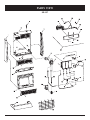
1
INSTALLATION INSTRUCTIONS
AND
OWNER'S MANUAL
UNVENTED
ROOM HEATER
MODELS
SR-10T-3 SR-18T-3 SR-30T-3
SR-30T SHOWN
Installer: Please leave these instructions with
the consumer.
Consumer: Please retain these instructions
for future use.
WARNING: If the information in this
manual is not followed exactly, a fire or
explosion may result causing property
damage, personal injury or loss of life.
— Do not store or use gasoline or other
flammable vapors and liquids in the
vicinity of this or any other appliance.
— WHAT TO DO IF YOU SMELL GAS
•
•
•
•
Do not try to light any appliance.
Do not touch any electrical switch;
do not use any phone in your building.
Immediately call your gas supplier
from a neighbor's phone. Follow the
gas supplier's instructions.
If you cannot reach your gas supplier,
call the fire department.
— Installation and service must be
performed by a qualified installer, service
agency or the gas supplier.
16009-1-0504
EFFECTIVE DATE
MAY 2004
This is an unvented gas-fired heater. It
uses air (oxygen) from the room in which
it is installed. Provisions for adequate combustion and ventilation air must be provided. Refer to page 6.
WARNING: If not installed, operated and
maintained in accordance with the manufacturer's instructions, this product could
expose you to substances in fuel or from
fuel combustion which can cause death or
serious illness.
WATER VAPOR: A BY-PRODUCT OF
UNVENTED ROOM HEATERS
Water vapor is a by-product of gas
combustion. An unvented room heater
produces approximately one (1) ounce
(30ml) of water for every 1,000 BTU's
(.3KW's) of gas input per hour. Refer to
page 6.
Page 1
TABLE OF CONTENTS
SECTION
PAGE
Important Safety Information ..................................................................................................................... 3
Safety Information for Users of LP Gas ..................................................................................................... 4
Introduction ................................................................................................................................................ 5
Specifications ............................................................................................................................................. 5
Water Vapor: A By-Product of Unvented Room Heaters .......................................................................... 6
Provisions for Adequate Combustion and Ventilation Air ......................................................................... 6
Gas Supply .................................................................................................................................................. 7
SR-10T Clearances ..................................................................................................................................... 8
SR-18T Clearances ..................................................................................................................................... 9
SR-30T Clearances ..................................................................................................................................... 9
Wall Mount Installation ....................................................................................................................... 10-11
Optional Floor Stand Installation ............................................................................................................. 11
Lighting Instructions ................................................................................................................................ 12
Main Burner Flame Characteristics .......................................................................................................... 13
Pilot Flame Characteristics ....................................................................................................................... 14
Thermostat Operation ............................................................................................................................... 14
Appliance Maintenance ............................................................................................................................ 15
Troubleshooting ........................................................................................................................................ 16
How to Order Repair Parts ....................................................................................................................... 16
SR-10T Parts List ..................................................................................................................................... 16
SR-18T and SR-30T Parts List ................................................................................................................. 17
SR-10T Parts View ................................................................................................................................... 18
SR-18T Parts View ................................................................................................................................... 19
SR-30T Parts View ................................................................................................................................... 20
Optional Blower Installation Instructions............................................................................................ 21-22
Service Notes ............................................................................................................................................ 23
Page 2
16009-1-0504
IMPORTANT SAFETY INFORMATION
THIS IS A HEATING APPLIANCE
DO NOT OPERATE THIS APPLIANCE WITHOUT FRONT PANEL INSTALLED.
• An unvented room heater having an input rating of
more than 6,000 Btu per hour shall not be installed in a
bathroom.
• An unvented room heater having an input rating of more
than 10,000 Btu per hour shall not be installed in a
bedroom or bathroom.
• Due to high temperatures, the appliance should be located
out of traffic and away from furniture and draperies.
• Children and adults should be alerted to the hazard of
high surface temperature and should stay away to avoid
burns or clothing ignition.
• Young children should be carefully supervised when they
are in the same room with the appliance.
• Installation and repair should be done by a QUALIFIED
SERVICE PERSON. The appliance should be inspected
before use and at least annually by a professional service
person. More frequent cleaning may be required due to
excessive lint from carpeting, bedding materials, etc. It is
imperative that control compartments, burners and
circulating air passageways of the appliance be kept clean.
• DO NOT use this room heater if any part has been under
water. Immediately call a qualified service technician to
inspect the room heater and to replace any part of the
control system and any gas control which has been under
water.
• Do not place clothing or other flammable material on or
near the appliance.
• WARNING: ANY CHANGE TO THIS HEATER OR ITS
CONTROLS CAN BE DANGEROUS.
Any safety screen or guard removed for servicing an
appliance must be replaced prior to operating the heater.
• Due to high surface temperatures, keep children, clothing
and furniture away.
• Keep appliance area clear and free from combustible
materials, gasoline and other flammable vapors and liquids
• WARNING: Failure to keep the primary air opening(s) of
the burner(s) clean may result in sooting and property
damage.
WARNING
When used without adequate combustion and ventilation
air, heater may give off CARBON MONOXIDE, an odorless, poisonous gas.
Do not install heater until all necessary provisions are
made for combustion and ventilation air. Consult the
written instructions provided with the heater for information concerning combustion and ventilation air. In
the absence of instructions, refer to the National Fuel
Gas Code, ANSI Z223.1, Section 5.3 or applicable local
codes.
This heater is equipped with a PILOT LIGHT SAFETY
SYSTEM designed to turn off the heater if not enough fresh
air is available.
DO NOT TAMPER WITH PILOT LIGHT SAFETY
SYSTEM!
If heater shuts off, do not relight until you provide fresh air.
If heater keeps shutting off, have it serviced. Keep burner
and control compartment clean.
16009-1-0504
CARBON MONOXIDE POISONING MAY LEAD TO
DEATH.
Early signs of carbon monoxide poisoning resemble the flu,
with headache, dizziness and/or nausea. If you have these
signs, heater may not be working properly. Get fresh air at
once! Have heater serviced.
Some people — pregnant women, persons with heart or
lung disease, anemia, those under the influence of alcohol,
those at high altitudes — are more affected by carbon
monoxide than others.
The pilot light safety system senses the depletion of oxygen
at its location. If this heater is installed in a structure having
a high vertical dimension, the possibility exists that the
oxygen supply at the higher levels will be less than that at
the heater. In this type of application, a fan to circulate the
structure air will minimize this effect. The use of this fan
will also improve the comfort level in the structure. When
a fan is used to circulate air, it should be located so that the
air flow is not directed at the burner.
Page 3
SAFETY INFORMATION FOR USERS OF LP-GAS
Propane (LP-Gas) is a flammable gas which can cause fires
and explosions. In its natural state, propane is odorless and
colorless. You may not know all the following safety precautions which can protect both you and your family from an
accident. Read them carefully now, then review them point
by point with the members of your household. Someday
when there may not be a minute to lose, everyone's safety will
depend on knowing exactly what to do. If, after reading the
following information, you feel you still need more information, please contact your gas supplier.
LP-GAS WARNING ODOR
•
•
•
•
If a gas leak happens, you should be able to smell the gas because of the odorant put in the LP-Gas.
That's your signal to go into immediate action!
Do not operate electric switches, light matches, use your
• Use your neighbor's phone and call a trained LP-Gas service
phone. Do not do anything that could ignite the gas.
person and the fire department. Even though you may not
Get everyone out of the building, vehicle, trailer, or area. Do
continue to smell gas, do not turn on the gas again. Do not rethat IMMEDIATELY.
enter the building, vehicle, trailer, or area.
Close all gas tank or cylinder supply valves.
• Finally, let the service man and firefighters check for
LP-Gas is heavier than air and may settle in low areas such
escaped gas. Have them air out the area before you return.
as basements. When you have reason to suspect a gas leak,
Properly trained LP-Gas service people should repair the
keep out of basements and other low areas. Stay out until
leak, then check and relight the gas appliance for you.
firefighters declare them to be safe.
NO ODOR DETECTED - ODOR FADE
Some people cannot smell well. Some people cannot smell the
odor of the chemical put into the gas. You must find out if you
can smell the odorant in propane. Smoking can decrease your
ability to smell. Being around an odor for a time can affect your
sensitivity or ability to detect that odor. Sometimes other odors
in the area mask the gas odor. People may not smell the gas odor
or their minds are on something else. Thinking about smelling a
gas odor can make it easier to smell.
The odorant in LP-gas is colorless, and it can fade under
some circumstances. For example, if there is an underground
leak, the movement of the gas through soil can filter the odorant.
Odorants in LP-Gas also are subject to oxidation. This fading can
occur if there is rust inside the storage tank or in iron gas pipes.
The odorant in escaped gas can adsorb or absorb onto or into
walls, masonry and other materials and fabrics in a room. That
will take some of the odorant out of the gas, reducing its odor
intensity.
LP-Gas may stratify in a closed area, and the odor intensity could
vary at different levels. Since it is heavier than air, there may be
more odor at lower levels. Always be sensitive to the slightest
gas odor. If you detect any odor, treat it as a serious leak.
Immediately go into action as instructed earlier.
SOME POINTS TO REMEMBER
• Learn to recognize the odor of LP-gas. Your local LP-Gas
Dealer can give you a "Scratch and Sniff" pamphlet. Use it to
find out what the propane odor smells like. If you suspect that
your LP-Gas has a weak or abnormal odor, call your LP-Gas
Dealer.
• If you are not qualified, do not light pilot lights, perform
service, or make adjustments to appliances on the LP-Gas
system. If you are qualified, consciously think about the odor
of LP-Gas prior to and while lighting pilot lights or performing service or making adjustments.
• Sometimes a basement or a closed-up house has a musty
smell that can cover up the LP-Gas odor. Do not try to light
pilot lights, perform service, or make adjustments in an area
where the conditions are such that you may not detect the
odor if there has been a leak of LP-Gas.
• Odor fade, due to oxidation by rust or adsorption on walls of
new cylinders and tanks, is possible. Therefore, people
should be particularly alert and careful when new tanks or
cylinders are placed in service. Odor fade can occur in new
tanks, or reinstalled old tanks, if they are filled and allowed
Page 4
to set too long before refilling. Cylinders and tanks which
have been out of service for a time may develop internal rust
which will cause odor fade. If such conditions are suspected
to exist, a periodic sniff test of the gas is advisable. If you
have any question about the gas odor, call your LP-gas
dealer. A periodic sniff test of the LP-gas is a good safety
measure under any condition.
• If, at any time, you do not smell the LP-Gas odorant and you
think you should, assume you have a leak. Then take the same
immediate action recommended above for the occasion when
you do detect the odorized LP-Gas.
• If you experience a complete "gas out," (the container is
under no vapor pressure), turn the tank valve off immediately. If the container valve is left on, the container may draw
in some air through openings such as pilot light orifices. If
this occurs, some new internal rusting could occur. If the
valve is left open, then treat the container as a new tank.
Always be sure your container is under vapor pressure by
turning it off at the container before it goes completely empty
or having it refilled before it is completely empty.
16009-1-0504
INTRODUCTION
Instructions to Installer
1. Installer must leave instruction manual with owner after
installation.
2. Installer must have owner fill out and mail warranty card
supplied with unvented room heater.
3. Installer should show owner how to start and operate unvented
room heater.
Always consult your local Building Department regarding
regulations, codes or ordinances which apply to the installation of
an unvented room heater.
Important
All correspondence should refer to complete Model Number,
Serial Number and type of gas.
Well Head Gas Installations
Some natural gas utilities use "well head" gas. This may affect the
Btu output of the unit. Contact the gas company for the heating
value. Contact the manufacturer or your gas company before
changing spud/orifice size.
This appliance is only for use with the type of gas indicated on the
rating plate. This appliance is not convertible for use with other
gases.
Qualified Installing Agency
Installation and replacement of gas piping, gas utilization equipment
or accessories and repair and servicing of equipment shall be
performed only by a qualified agency. The term "qualified agency"
means any individual, firm, corporation, or company that either in
person or through a representative is engaged in and is responsible
for (a) the installation, testing, or replacement of gas piping or (b)
the connection, installation, testing, repair, or servicing of
equipment; that is experienced in such work; that is familiar with
all precautions required, and that has complied with all the
requirements of the authority having jurisdiction.
General Information
This appliance is design certified in accordance with American
National Standards Institute Z21.11.2b by the Canadian Standards
Association Laboratories as an Unvented Room Heater and shall
be installed according to these instructions.
The installation must conform with local codes or, in the absence
of local codes, with the National Fuel Gas Code, ANSI Z223.1
(latest edition).*
*Available from the American National Standards Institute, Inc.,
11 West 42nd St., New York, N.Y. 10036.
Any alteration of the original design, installed other than as
shown in these instructions or use with a type of gas not shown
on the rating plate is the responsibility of the person and
company making the change.
High Altitudes
For altitudes/elevations above 2,000 feet (610m) ratings should
be reduced at the rate of 4 percent for each 1,000 feet (305m)
above sea level. Contact the manufacturer or your gas company
before changing spud/orifice size.
This appliance may be installed in an aftermarket* permanently
located, manufactured (mobile) home, where not prohibited by
state or local codes.
*Aftermarket: Completion of sale, not for purpose of resale, from
the manufacturer.
SPECIFICATIONS
Model
Input BTU/HR (KW/H) Five Plaques
BTU/HR (KW/H) Three Plaques
BTU/HR (KW/H) One Plaque
Height
Width
Depth
Gas Inlet
Accessories
Blower
Floor Stand
SR-10T
SR-18T
SR-30T
—
—
10,000 (2.9)
22" (559mm)
11 7/8" (302mm)
6 1/2" (165mm)
3/8" (10mm)
—
18,000 (5.3)
—
22" (559mm)
18" (457mm)
6 1/2" (165mm)
3/8" (10mm)
30,000 (8.8)
—
—
22" (559mm)
24 1/8" (613mm)
6 1/2" (165mm)
3/8" (10mm)
—
SRS-10*
SRB-18T
SRS-18
SRB-30T
SRS-30
*Floor stand can not be used in a bedroom installation. SR-10T must be wall mounted in a bedroom installation.
The bathroom or bedroom must be an unconfined space. ANSI Z223.1/NFPA54 defines an unconfined space as “a space whose volume
3
is not less than 50 cubic feet per 1,000 Btu per hour (4.8m per kw) of the aggregate input rating of all appliances installed in that space.”
16009-1-0504
Page 5
WATER VAPOR: A BY-PRODUCT OF UNVENTED ROOM HEATERS
Water vapor is a by-product of gas combustion. An unvented
room heater produces approximately one (1) ounce (30ml) of
water for every 1,000 BTU's (.3KW's) of gas input per hour.
Unvented room heaters must be used as supplemental heat (a
room) rather than a primary heat source (an entire house). In most
supplemental heat applications, the water vapor does not create a
problem. In most applications, the water vapor enhances the low
humidity atmosphere experienced during cold weather.
The following steps will help insure that water vapor does not
become a problem.
1. Be sure the heater is sized properly for the application, including
ample combustion air and circulation air.
2. If high humidity is experienced, a dehumidifier may be used to
help lower the water vapor content of the air.
3. Do not use an unvented room heater as the primary heat source
(an entire house).
PROVISIONS FOR ADEQUATE COMBUSTION & VENTILATION AIR
This heater shall not be installed in a confined space or unusually
tight construction unless provisions are provided for adequate
combustion and ventilation air.
The National Fuel Gas Code, ANSI Z223.1 defines a confined
space as a space whose volume is less than 50 cubic feet per 1,000
Btu per hour (4.8m3 per kw) of the aggregate input rating of all
appliances installed in that space and an unconfined space as a
space whose volume is not less than 50 cubic feet per 1,000 Btu
per hour (4.8m3 per kw) of the aggregate input rating of all
appliances installed in that space. Rooms communicating directly with the space in which the appliances are installed,
through openings not furnished with doors, are considered a part
of the unconfined space.
The following example is for determining the volume of a typical
area in which the SR-30T may be located and for determining if
this area fits the definition of an unconfined space.
The input of the SR-30T is 30,000 Btu per hour. Based on the 50
cubic feet per 1,000 Btu per hour formula, the minimum area that
is an unconfined space for installation of the SR-30T is 1,500
cubic feet, 50 cubic feet x 30 = 1,500 cubic feet. To determine the
cubic feet of the area in which the SR-30T is to be installed,
measure the length, width and height of the area. Example: The
area measures 16 feet in length, 12 feet in width and 8 feet in
height, the area is 1,536 cubic feet. The SR-30T can be installed
in this unconfined space with no requirement to provide additional combustion and ventilation air.
Page 6
Warning: If the area in which the heater may be operated is
smaller than that defined as an unconfined space or if the building
is of unusually tight construction, provide adequate combustion
and ventilation air by one of the methods described in the
National Fuel Gas Code, ANSI Z223.1, Section 5.3 or applicable
local codes.
Unusually Tight Construction
The air that leaks around doors and windows may provide enough
fresh air for combustion and ventilation. However, in buildings of
unusually tight construction, you must provide additional fresh
air.
Unusually tight construction is defined as construction
where:
a. Walls and ceilings exposed to the outside atmosphere have
a continuous water vapor retarder with a rating of one perm
or less with openings gasketed or sealed, and
b. Weatherstripping has been added on openable windows
and doors, and
c. Caulking or sealants are applied to areas such as joints
around window and door frames, between sole plates and
floors, between wall-ceiling joints, between wall panels, at
penetrations for plumbing, electrical, and gas lines, and at
other openings.
If the SR-30T heater is installed in a building of unusually tight
construction, adequate air for combustion, ventilation and dilution of flue gases shall be provided in accordance with ANSI
Z223.1/NFPA54.
16009-1-0504
GAS SUPPLY
The gas line can be routed either through the floor or wall. The gas
line opening should be made at this time. Location of the opening
will be determined by the position of floor joists and the valve and
union used for servicing.
Gas Supply
Check all local codes for requirements, especially for the size and
type of gas supply line required.
A gas valve and ground joint union should be installed in the gas
line upstream of the gas control to aid in servicing. It is required
by the National Fuel Gas Code that a drip line be installed near the
gas inlet. This should consist of a vertical length of pipe tee
connected into the gas line that is capped on the bottom in which
condensation and foreign particles may collect.
Recommended Gas Pipe Diameter
Pipe Length
(Feet)
0-10
10-40
40-100
100-150
Schedule 40 Pipe
Inside Diameter
Nat.
L.P.
1/2"
3/8"
1.3 cm
1.0 cm
1/2"
1/2"
1.3 cm
1.3 cm
1/2"
1/2"
1.3 cm
1.3 cm
3/4"
1/2"
1.9 cm
1.3 cm
Tubing, Type L
Outside Diameter
Nat.
L.P.
1/2"
3/8"
1.3 cm
1.0 cm
5/8"
1/2"
1.6 cm
1.3 cm
3/4"
1/2"
1.9 cm
1.3 cm
7/8"
3/4"
2.2 cm
1.9 cm
Note: Never use plastic pipe. Check to confirm whether your local
codes allow copper tubing or galvanized.
Note: Since some municipalities have additional local codes, it is
always best to consult your local authority and installation code.
Dimensions Apply to SR-10T, SR-18T and SR-30T
Figure 1
Installing a New Main Gas Cock
Each appliance should have its own manual gas cock..
A manual main gas cock should be located in the vicinity of the
unit. Where none exists, or where its size or location is not
adequate, contact your local authorized installer for installation
or relocation.
Compounds used on threaded joints of gas piping shall be
resistant to the action of liquefied petroleum gases. The gas lines
must be checked for leaks by the installer. This should be done
with a soap solution watching for bubbles on all exposed connections, and if unexposed, a pressure test should be made.
Never use an exposed flame to check for leaks. Appliance
must be disconnected from piping at inlet of control valve and
pipe capped or plugged for pressure test. Never pressure test
with appliance connected; control valve will sustain damage!
16009-1-0504
Figure 2
Method of Installing a Tee Fitting Sediment Trap (Figure 2)
The use of the following gas connectors is recommended:
— ANS Z21.24 Appliance Connectors of Corrugated Metal
Tubing and Fittings
— ANS Z21.45 Assembled Flexible Appliance Connectors of
Other Than All-Metal Construction
The above connectors may be used if acceptable by the authority
having jurisdiction.
Pressure Testing of the Gas Supply System
1. To check the inlet pressure to the gas valve, a 1/8" (3mm)
N.P.T. plugged tapping, accessible for test gauge connection,
must be placed immediately upstream of the gas supply
connection to the appliance.
2. The appliance and its appliance main gas valve must be
disconnected from the gas supply piping system during any
pressure testing of that system at test pressures in excess of 1/
2 psig (3.5 kPa).
3. The appliance must be isolated from the gas supply piping
system by closing its equipment shutoff valve during any
pressure testing of the gas supply piping system at test
pressures equal to or less than 1/2 psig (3.5 kPa).
Attention! If one of the above procedures results in pressures in
excess of 1/2 psig (14" w.c.) (3.5 kPa) on the appliance gas valve,
it will result in a hazardous condition.
Checking Manifold Pressure
Natural gas will have a manifold pressure of approximately 6.0"
w.c. (1.49kPa) at the pressure regulator outlet with the inlet
pressure to the pressure regulator from a minimum of 7.0" w.c.
(1.743kPa) for the purpose of input adjustment to a maximum of
10.5" w.c. (2.615kPa). Propane/LP gas will have a manifold
pressure approximately 10.0" w.c. (2.49kPa) at the pressure
regulator outlet with the inlet pressure to the pressure regulator
from a minimum of 11.0" w.c. (2.739kPa) for the purpose of input
adjustment to a maximum of 13.0" w.c. (3.237kPa).
A test gage connection is located downstream of the gas appliance
pressure regulator for measuring gas pressure. The connection is
a 1/8 inch (3mm) N.P.T. plugged tapping.
Page 7
SR-10T CLEARANCES
When facing the front of the appliance the following minimum
clearances to combustible construction must be maintained.
Left side 6 inches (152mm). Right side 6 inches (152mm).
Do not install in alcove or closet.
Rear wall 0 inches (0mm). Ceiling 24 inches (610mm).
Minimum vertical clearance from a projection above the
appliance (shelves, window sills, etc.) 14 inches (356mm).
Maximum horizontal extension of projection above the
appliance 12 inches (305mm).
Floor (top surface of carpeting, tile, etc.) 2 inches (51mm).
12" MAX
(305mm)
24 " MIN
(610mm)
14" MIN
(356mm)
0" (0mm) CLEARANCE
TO REAR WALL
Provide adequate clearances around air openings.
Adequate accessibility clearances for purposes of servicing and
proper operation must be provided.
2 " MIN
(51mm)
24 " MIN
(610mm)
Figure 4 (SR-10T)
14" MIN
(356mm)
6 " MIN
(152mm)
6 "MIN
(152mm)
2 " MIN
(51mm)
Figure 3 (SR-10T)
Page 8
16009-1-0504
SR-18T CLEARANCES
When facing the front of the appliance the following minimum
clearances to combustible construction must be maintained.
Left side 6 inches (152mm). Right side 6 inches (152mm).
Do not install in alcove or closet.
Rear wall 0 inches (0mm). Ceiling 36 inches (914mm).
Minimum vertical clearance from a projection above the
appliance (shelves, window sills, etc.) 36 inches (914mm).
Floor (top surface of carpeting, tile, etc.) 2 inches (51mm).
36" (914mm) MIN
6" (152mm)
MIN
6" (152mm)
MIN
Provide adequate clearances around air openings.
Adequate accessibility clearances for purposes of servicing and
proper operation must be provided.
2" (51mm)
MIN
Figure 5 (SR-18T)
SR-30T CLEARANCES
When facing the front of the appliance the following minimum
clearances to combustible construction must be maintained.
Left side 8 inches (203mm). Right side 8 inches (203mm).
Do not install in alcove or closet.
Rear wall 0 inches (0mm). Ceiling 36 inches (914mm).
Minimum vertical clearance from a projection above the
appliance (shelves, window sills, etc.) 36 inches (914mm).
Floor (top surface of carpeting, tile, etc.) 2 inches (51mm).
36" (914mm) MIN
8"
(203mm)
MIN
8"
(203mm)
MIN
Provide adequate clearances around air openings.
Adequate accessibility clearances for purposes of servicing and
proper operation must be provided.
2"
(51mm)
MIN
Figure 6 (SR-30T)
16009-1-0504
Page 9
WALL MOUNT INSTALLATION
Refer to Figures 7, 8 and 9 for measurements in order to locate (4)
mounting holes on wall. Figures 7, 8 and 9 are the front views of
the heaters.
1. Remove lower louver from casing assembly (2 screws).
2. Remove reflector from casing assembly (2 screws).
3. Remove upper louver from casing assembly (2 screws).
24 1/8"
(613mm)
2"
(51)
20 1/8"
(511mm)
2"
(51)
1 3/32"
(28mm)
11 13/16"
(300mm)
7 13/16"
(198mm)
1 3/32"
2"
(51)
2"
(51)
(28mm)
18 7/8"
(479mm)
18 7/8"
(479mm)
22"
(559mm)
4 1/32"
(102mm)
4 1/32
(102mm)
MIN
22"
(559mm)
2 1/32" (52mm)
2" (51mm) MIN
2"MIN (51mm)
Figure 9 (SR-30T)
On Solid Wall
1. After locating mounting holes, attach (4) #10 x 1" (25mm)
screws provided into the wall. Do not completely tighten
screwheads to the wall, leave a 1/8" (3mm) gap between
screwheads and wall.
2. Mount heater onto the (4) screwheads and complete
tightening screwheads into the wall.
Attention! Use the following steps to properly align the
upper louver and the reflector with the heat shield.
a. When replacing upper louver, be sure the bottom lip of
upper louver goes behind the heat shield.
b. When replacing reflector, be sure the top lip of reflector
goes in front of the heat shield.
3. Connect the gas line.
Figure 7 (SR-10T)
18"
(457mm)
2"
(51)
14"
(356mm)
2"
(51)
1 3/32
(28mm)
18 7/8"
(479mm)
22"
(559mm)
2 1/32 (52mm)
4 1/32"
(102mm) MIN
2" (51mm)
On Sheet Rock Wall
1. After locating mounting holes, drill (4) 5/16" (8mm)
diameter holes into the wall.
2. Insert (4) plastic expansion anchors provided into the
holes.
3. Tighten (4) #10 x 1" (25mm) screws provided into the
plastic expansion anchors. Do not completely tighten
screwheads to the plastic expansion anchors, leave a 1/8"
(3mm) gap between screwheads and plastic expansion
anchors.
Figure 8 (SR-18T)
Page 10
16009-1-0504
4. Mount heater onto the (4) screwheads and complete
tightening the screwheads to the plastic expansion anchors.
Attention! Use the following steps to properly align the
upper louver and the reflector with the heat shield.
a. When replacing upper louver, be sure the bottom lip of
upper louver goes behind the heat shield.
b. When replacing reflector, be sure the top lip of reflector
goes in front of the heat shield.
5. Connect the gas line.
Figure 10
OPTIONAL FLOOR STAND INSTALLATION
1. Align clearance holes on floor stand with screw holes on
bottom of heater, as shown in Figure 11.
2. Attach floor stand to heater with (4) screws provided with
floor stand.
3. Connect the gas line.
*Floor stand can not be used in a bedroom installation. SR-10T
must be wall mounted in a bedroom installation.
Installation on Rugs and Tile
If this appliance is installed directly on carpeting, tile or other
combustible material, other than wood flooring, the appliance
shall be installed on a metal or wood panel extending the full
width and depth of the appliance.
Attention: Optional Floor Stand meets requirement.
The base referred to above does not mean the fire-proof base as
used on wood stoves. The protection is for rugs that are extremely
thick and light colored tile.
SR-30T SHOWN
Figure 11
16009-1-0504
Page 11
LIGHTING INSTRUCTIONS
FOR YOUR SAFETY READ BEFORE LIGHTING
WARNING: If you do not follow these instructions exactly, a fire or explosion may result
causing property damage, personal injury or loss of life.
A. This appliance has a pilot which must be lighted by
hand. When lighting the pilot, follow these instructions
exactly.
B. BEFORE LIGHTING smell all around the appliance
area for gas. Be sure to smell next to the floor because
some gas is heavier than air and will settle on the floor.
WHAT TO DO IF YOU SMELL GAS
• Do not try to light any appliance.
• Do not touch any electrical switch;
do not use any phone in your building.
• Immediately call your gas supplier from a neighbor's phone. Follow the gas supplier's instructions.
• If you cannot reach your gas supplier, call the fire
department.
C. Use only your hand to push in or turn the gas control
knob. Never use tools. If the knob will not push in or
turn by hand, don't try to repair it; call a qualified
service technician. Force or attempted repair may
result in a fire or explosion.
D. Do not use this appliance if any part has been under
water. Immediately call a qualified service technician to inspect the appliance and to replace any part
of the control system and any gas control which has
been under water.
LIGHTING INSTRUCTIONS
1.
STOP! Read the safety information above.
2.
Set thermostat (gas control knob) to lowest setting.
3.
Turn off all electric power to the appliance (if applicable).
4.
Push in gas control knob slightly and turn clockwise
to "OFF". Do not force.
5.
Wait ten (10) minutes to clear out any gas. Then smell
for gas, including near the floor. If you smell gas, STOP!
Follow "B" in the safety information above. If you don't
smell gas, go to the next step.
6.
Find pilot - the pilot is
attached at the bottom of
the burner assembly .
7.
Turn gas control knob
counterclockwise
8.
9.
to "PILOT."
10.
11.
12.
Push in gas control knob all the way and hold in.
Repeatedly push the piezo ignitor button until
pilot is lit (or use a match to light pilot). Continue
to hold the control knob in for about one (1) minute
after the pilot is lit. Release knob and it will pop
back up. Pilot should remain lit. If it goes out,
repeat steps 4 through 8.
• If knob does not pop up when released, stop and
immediately call your service technician or gas
supplier.
• If the pilot will not stay lit after several tries, turn
the gas control knob to "OFF" and call your
service technician or gas supplier.
Attention! Gas control has an INTERLOCK latching
device. When the pilot is initially lit and the safety
magnet is energized (pilot stays "ON") the INTERLOCK latching device becomes operative. If the gas
control is turned to the "OFF" position or gas flow to
the appliance is shut off, the pilot cannot be relighted
until the safety magnet is de-energized (approximately 60 seconds). There will be an audible "click"
when the safety magnet in the gas control is deenergized. Pilot can now be relighted. Repeat steps 4
through 8.
Turn gas control knob counterclockwise
to
"HI".
Turn on all electric power to appliance (if applicable).
Set thermostat (gas control knob) to desired setting
from "HI" to "LO".
TO TURN OFF GAS TO APPLIANCE
1.
Set thermostat (gas control knob) to lowest setting.
2.
Turn off all electric power to appliance if service is to be
performed (if applicable).
Page 12
3.
Push in gas control knob slightly and turn clockwise
to "OFF". Do not force.
16009-1-0504
MAIN BURNER FLAME CHARACTERISTICS
SR-10T, SR-18T and SR-30T Main Burner Flame (Figure12)
The main burner flame will have a red-orange glow over the
surface of the ceramic plaques. A few small, hairline cracks may
form over the surface of the ceramic plaques or at the edges of the
ceramic plaques where they have been cemented into position on
the burner assembly frame. These small, hairline cracks will not
affect the operation or performance of the ceramic plaques. Only,
when large cracks develop, with blue flames escaping from the
large cracks, should you contact your QUALIFIED SERVICE
PERSON.
A red-orange haze that is visible on the ceramic plaques is
acceptable. A blue flame that rolls out at the top of the ceramic
plaques indicates an accumulation of dust, lint or spider webs
inside the casing assembly and main burner assembly. Use the
following procedure to inspect the casing assembly and main
burner assembly.
1. Turn OFF gas supply to the heater.
2. Turn OFF electric supply to the heater if optional blower is
installed in heater.
3. Remove lower louver from casing assembly ( 2 screws).
4. Remove reflector from casing assembly (2 screws).
5. Inspect interior of casing assembly for accumulation of dust,
lint or spider webs. If necessary, clean interior of casing
assembly with a vacuum cleaner or apply air pressure. Do not
damage any components within casing assembly when you
are cleaning.
6. Remove pilot bracket from main burner assembly (2 screws).
7. Pivot pilot bracket with attached pilot away from main burner
assembly (do not damage pilot tubing).
8. Inspect main burner orifice(s) through the rectangular
opening(s) in the venturi (throat) of the main burner(s). Dust,
lint and spider webs can accumulate on top of the main burner
orifice(s). If necessary, clean main burner orifice(s) with a
vacuum cleaner or apply air pressure. To thoroughly clean the
main burner orifice(s) proceed to Step 9.
9. Disconnect supply tubing from orifice holder(s).
10.Remove orifice holder from venturi of main burner assembly
(1 screw for each orifice holder).
11.Remove main burner orifice from orifice holder.
12.Apply air pressure through main burner orifice and orifice
holder to remove dust, lint or spider webs.
13.Apply air pressure into ceramic plaque(s) to remove dust, lint
or spider webs.
14.As parts are being replaced in reverse order, check for gas
leaks at all gas connections before lower louver is replaced
onto casing assembly.
SR-30T SHOWN
Figure 12
16009-1-0504
Page 13
PILOT FLAME CHARACTERISTICS
The correct flame will be blue and will extend beyond the
thermocouple. The flame will surround the thermocouple just
below the tip. A slight yellow flame may occur where the pilot
flame and main burner flame meet.
2.
Blow air pressure through the holes indicated by the arrows.
This will blow our foreign materials such as dust, lint and
spider webs. Tighten nut B also by grasping nut A.
Figure 14
Figure 13
Oxygen Depletion Sensor Pilot (Figure 14)
When the pilot has a large yellow tip flame, clean the Oxygen
Depletion Sensor as follows:
1.
Warning:
Never use needles, wires, or similar cylindrical objects to
clean the pilot to avoid damaging the calibrated ruby that
controls the gas flow.
Clean the ODS pilot by loosening nut B from the pilot tubing.
When this procedure is required, grasp nut A with an open
end wrench.
THERMOSTAT OPERATION
To ignite main burner, turn gas control knob counterclockwise
toward HI setting. To shut down main burner, turn gas control
knob clockwise toward LO setting.
The SR-10T has an input of 10,000 BTUH (2.9KW/H). The
hydraulic thermostat bulb is located at the casing assembly
bottom. When the hydraulic thermostat bulb senses the need
for heat, the unit cycles “ON” at a full input rate of 10,000
BTUH (2.9KW/H). The unit remains at this full input rate until
the hydraulic thermostat bulb is “satisfied.” When the hydraulic thermostat bulb is “satisfied” the burner will shut “OFF”
with the pilot flame remaining “ON.”
The SR-18T has an input of 18,000 BTUH (5.3KW/H). The
hydraulic thermostat bulb is located at the casing assembly
bottom. When the hydraulic thermostat bulb senses the need
for heat, the unit cycles “ON” at a full input rate of 18,000
BTUH (5.3KW/H). The unit remains at this full input rate until
the hydraulic thermostat bulb is “satisfied.” When the hydraulic thermostat bulb is “satisfied” the burner will shut “OFF”
with the pilot flame remaining “ON.”
Note: The burner does not modulate between “ON” and the
pilot flame. When the SR-18T is “ON,” all three ceramic
plaques will “glow.” There will never be a time when only one
or two ceramic plaques are “glowing.”
The SR-30T has an input of 30,000 BTUH (8.8KW/H). The
hydraulic thermostat bulb is located at the casing assembly
bottom. When the hydraulic thermostat bulb senses the need for
heat, the unit cycles "ON" at a full input rate of 30,000 BTUH
Page 14
(8.8KW/H). The unit remains at this full input rate until the
hydraulic thermostat bulb is "satisfied." When the hydraulic
thermostat bulb is "satisfied" the burner will shut "OFF" with the
pilot flame remaining "ON."
Note: The burner does not modulate between "ON" and the pilot
flame. When the SR-30T is "ON," all five ceramic plaques will
"glow." There will never be a time when only one or three ceramic
plaques are "glowing."
The LO and HI setting has temperature range of approximately
55°F (12.78°C) to 90°F (32.22°C), respectively. This is the
temperature at the hydraulic thermostat bulb not the room temperature. The owner is advised to determine the particular heat
setting that is desired for comfort, as heating requirements are
different for every owner.
Attention: If the owner does not want the main burner to ignite
and turns the gas control knob to the LO setting, the main burner
will still ignite if the temperature at the hydraulic thermostat bulb
drops to 55°F (12.78°C).
If no heat is desired, turn the gas control knob to the PILOT
position.
Main Burner Operation
Description of Gas Control Knob:
OFF position.
PILOT position.
LO/HI will allow the hydraulic thermostat bulb to cycle the heater
ON and OFF.
16009-1-0504
APPLIANCE MAINTENANCE
Removing Pilot/Thermocouple From Main Burner
Assembly
Attention: The thermocouple CAN NOT be replaced as an
individual item. You must order a new pilot when replacing
thermocouple.
1. Turn OFF gas supply to the heater.
2. Turn OFF electrical supply to the heater if optional blower is
installed in heater.
3. Remove lower louver from casing assembly (2 screws).
4. Remove reflector from casing assembly (2 screws).
5. Disconnect pilot tubing from pilot (see Figure 14, Page 14).
Grasp nut A with a wrench when removing nut B with a
second wrench.
6. Remove pilot from pilot bracket (2 screws).
7. Remove thermocouple lead from gas valve.
8. As parts are being replaced in reverse order, check for gas
leaks at all gas connections before lower louver is replaced
onto casing assembly.
Removing Main Burner Orifice(s) From
Main Burner Assembly
1. Turn OFF gas supply to the heater.
2. Turn OFF electrical supply to the heater if optional blower is
installed in heater.
3. Remove lower louver from casing assembly (2 screws).
4. Remove reflector from casing assembly (2 screws).
5. Remove pilot bracket from main burner assembly (2 screws).
6. Pivot pilot bracket with attached pilot away from main burner
assembly (do not damage pilot tubing).
7. Disconnect supply tubing from orifice holder(s).
8. Remove orifice holder from venturi of main burner assembly
(1 screw for each orifice holder).
9. Remove main burner orifice from orifice holder. Attention:
The number stamped on the main burner orifice is a
millimeter diameter.
10.As parts are being replaced in reverse order, check for gas
leaks at all gas connections before lower louver is replaced
onto casing assembly.
Removing Gas Valve From Casing Assembly
1. Turn OFF gas supply to the heater.
2. Turn OFF electrical supply to the heater if optional blower is
installed in heater.
3. Remove lower louver from casing assembly (2 screws).
4. Remove reflector from casing assembly (2 screws).
16009-1-0504
5. Remove upper louver from casing assembly (2 screws).
6. If installed, remove optional blower assembly (4 screws).
7. Disconnect inlet supply tubing, outlet supply tubing, pilot
supply tubing and thermocouple lead from gas valve.
8. If heater is attached to wall, disconnect gas supply line from
inlet regulator.
9. Remove heater from wall.
10. Remove gas valve bracket from casing assembly (4 screws to
be removed are located on casing assembly back).
11. Remove hydraulic thermostat bulb from thermostat bulb clip
located at casing assembly bottom.
12. Remove gas valve from gas valve bracket.
13. As parts are being replaced in reverse order, check for gas
leaks at all gas connections before upper louver, reflector and
lower louver are replaced onto casing assembly.
Removing Main Burner From Casing Assembly
1. Turn OFF gas supply to the heater.
2. Turn OFF electrical supply to the heater if optional blower is
installed in heater.
3. Remove lower louver from casing assembly (2 screws).
4. Remove reflector from casing assembly (2 screws).
5. Disconnect supply tubing from orifice holder(s).
6. Remove pilot bracket from main burner assembly (2 screws).
7. Remove main burner assembly from casing assembly (4
screws).
8. Remove orifice shield from main burner assembly. Attach
orifice shield to new main burner assembly.
9. As parts are being replaced in reverse order, check for gas
leaks at all gas connections before lower louver is replaced
onto casing assembly.
Piezo Pilot Ignitor Instructions
Depressing the ignitor button completely causes a spark to occur
at the pilot.
To light the pilot, it is important that the electrode be 1/8" (3mm)
from the pilot. The spark must occur at the point the pilot flame
hits the thermocouple.
On a new installation with air in the gas line, it is suggested that
a match be used. The match will light the pilot faster than the
piezo under this condition.
Page 15
TROUBLESHOOTING
1. Spark electrode does not produce spark.
a. Spark electrode broken - replace.
b. Ignitor wire may not be attached to spark electrode attach.
c. Ignitor wire damaged - replace.
d. Piezo ignitor defective - replace.
2. Spark electrode produces spark but pilot does not light.
a. No gas to heater - turn on gas.
b. PILOT position not properly aligned - turn gas control
knob to PILOT position and depress.
c. Pilot is blocked from spider web or dirt - clean pilot, see
Page 14.
3. Pilot flame does not stay "ON" when control knob is
released.
a. Control knob in PILOT position not completely
depressed or held in long enough.
b. INTERLOCK latching device is operative - see "Lighting
Instructions," Page 12, Step 9.
c. Thermocouple not tightened into gas control - tighten
thermocouple.
d. Pilot flame not surrounding thermocouple - clean pilot,
see Page 14.
e. Inlet gas pressure too low, contact gas supplier.
f. Thermocouple defective - replace.
g. Gas control defective - replace.
4. Main burner does not ignite.
a. Main burner orifice is blocked - clean, see "Main Burner
Flame Characteristics," Page 13. Attention: The number
stamped on the main burner orifice is a millimeter
diameter.
b. Inlet gas pressure too low, contact gas supplier.
5. Heater keeps shutting "OFF" during normal operation.
a. Pilot is blocked - clean pilot, see Page 14.
b. Inlet gas pressure too low, contact gas supplier
HOW TO ORDER REPAIR PARTS
Parts can be ordered only through your service person or dealer. For best results, the service person or dealer should order parts through
the distributor. Parts can be shipped directly to the service person/dealer.
All parts listed in the Parts List have a Part Number. When ordering parts, first obtain the Model Number from the name plate on your
equipment. Then determine the Part Number (not the Index Number) and the Description of each part from the following appropriate
illustration and list. Be sure to give all this information . . .
Unvented Heater Model Number
Part Description
Unvented Heater Serial Number
Part Number
Type of Gas (Propane or Natural)
Do not order bolts, screws, washers or nuts. They are standard hardware items and can be purchased at any local hardware store.
Shipments contingent upon strikes, fires and all causes beyond our control.
PARTS LIST
SR-10T
PLEASE NOTE: When ordering parts, it is very important that part number and description of part coincide.
INDEX
NUMBER
PART
NUMBER
1
2
3
4
5
6
7
8
13347
SR-180
R-2313
SR-008
SR-113
R-6563
12438
12437
9
10
10
11
12
13
13
14
15
10753
R-5097
R-5098
SR-158
R-2314
R-2317
R-2476
R-2331
R-6308
Page 16
DESCRIPTION
CASING SIDE ASSEMBLY - LEFT
CASING BACK
PIEZO IGNITOR
CASING SIDE ASSEMBLY - RIGHT
VALVE BRACKET
GAS VALVE -SIT
TUBING - GAS VALVE TO BURNER
TUBING - INLET REGULATOR TO GAS
VALVE
iNLET REGULATOR BRACKET
INLET REGULATOR - NAT
INLET REGULATOR - LPG
TUBING - GAS VALVE TO PILOT
ORIFICE HOLDER
MAIN BURNER ORIFICE - NAT
MAIN BURNER ORIFICE - LPG
BURNER
PILOT ASSEMBLY (LPG ONLY))
INDEX
NUMBER
PART
NUMBER
15
R-6307
16
17
18
18
19
20
21
22
23
24
25
R-6310
R-6309
SR-179
SR-032
SR-153
R-2305
SR-134
SR-129
SR-135
R-1992
SR-154
NS
NS
R-2390
SR-216
DESCRIPTION
(INCLUDES ITEMS 16 & 17)
PILOT ASSEMBLY (NAT ONLY))
(INCLUDES ITEMS 16 & 17)
PILOT THERMOCOUPLE
SPARK IGNITOR
PILOT BRACKET (NAT)
PILOT BRACKET (LPG)
ORIFICE SHIELD
CHROME GRILL
CASING LOUVER (2 REQUIRED)
REFLECTOR ASSEMBLY
HEAT SHIELD
BULB CLIP
OPTIONAL SRS-10 FLOOR STAND
KIT
IGNITOR WIRE
HARDWARE PACKAGE
Empire Comfort Systems, Inc. Nine Eighteen Freeburg Ave. Belleville, Illinois 62222-0529
16009-1-0504
PARTS LIST
SR-30T
SR-18T
PLEASE NOTE: When ordering parts, it is very important that part number and description of part coincide.
INDEX
NUMBER
PART
NUMBER
1
2
3
4
5
6
7
8
9
10
13348
SR-090
R-2313
SR-008
SR-113
R-6563
R-2330
SR-119
SR-032
R-6307
10
R-6308
11
12
13
R-6310
R-6309
R-2315
13
R-2498
14
15
R-2314
SR-204
16
SR-201
17
18
19
19
20
21
22
SR-098
R-2334
R-5097
R-5098
10753
12439
12437
23
24
25
26
27
28
R-2304
SR-076
SR-070
SR-077
R-1992
SR-120
29
SR-122
30
31
32
33
34
35
36
37
R-1454
R-1499
SR-196
R-2099
R-1468
R-2395
R-2503
R-2396
NS
NS
NS
SR-219
R-2390
SR-216
DESCRIPTION
CASING SIDE ASSEMBLY - LEFT
CASING BACK
PIEZO IGNITOR
CASING SIDE ASSEMBLY - RIGHT
VALVE BRACKET
GAS VALVE -SIT
BURNER
ORIFICE SHIELD
PILOT BRACKET
PILOT ASSEMBLY (NAT ONLY))
(INCLUDES ITEMS 11 & 12)
PILOT ASSEMBLY (LPG ONLY))
(INCLUDES ITEMS 11 & 12)
PILOT THERMOCOUPLE
SPARK IGNITOR
MAIN BURNER ORIFICE - NAT (3
REQUIRED)
MAIN BURNER ORIFICE - LPG (3
REQUIRED)
ORIFICE HOLDER (3 REQUIRED)
TUBING - MANIFOLD TO BURNER
TWO
TUBING - MANIFOLD TO BURNER
ONE AND THREE (2 REQUIRED)
TUBING - GAS VALVE TO PILOT
MANIFOLD
INLET REGULATOR - NAT
INLET REGULATOR - LPG
INLET REGULATOR BRACKET
TUBING - GAS VALVE TO MANIFOLD
TUBING - INLET REGULATOR TO
GAS VALVE
CHROME GRILL
CASING LOUVER (2 REQUIRED)
REFLECTOR ASSEMBLY
HEAT SHIELD
BULB CLIP
OPTIONAL SRS-18 FLOOR STAND
KIT
OPTIONAL SRB-18T BLOWER KIT
(INCLUDES 30 THROUGH 37)
BRASS BUSHING (4 REQUIRED)
RUBBER GROMMET (4 REQUIRED)
BLOWER PAN
CORD SET ASSEMBLY
BUSHING - HEYCO #SR5KN4
WIRE ASSEMBLY
FAN CONTROL
BLOWER (INCLUDES MOTOR, FAN,
AND FAN HOUSING)
BLOWER HARDWARE PACKAGE
IGNITOR WIRE
HARDWARE PACKAGE
INDEX
NUMBER
PART
NUMBER
1
2
3
4
5
6
7
8
9
10
13348
SR-041
R-2313
SR-008
SR-113
R-6563
R-2329
SR-114
SR-032
R-6307
10
R-6308
11
12
13
R-6310
R-6309
R-2315
13
R-2498
14
15
R-2314
SR-203
16
SR-202
17
SR-201
18
19
R-2333
12437
20
21
22
22
23
24
25
26
27
28
29
12440
10753
R-5097
R-5098
SR-054
R-2303
SR-017
SR-009
SR-018
R-1992
SR-115
30
SR-116
31
32
33
34
35
36
37
38
R-1454
R-1499
SR-198
R-2099
R-1468
R-2395
R-2503
R-2396
NS
NS
NS
SR-219
R-2390
SR-216
DESCRIPTION
CASING SIDE ASSEMBLY - LEFT
CASING BACK
PIEZO IGNITOR
CASING SIDE ASSEMBLY - RIGHT
VALVE BRACKET
GAS VALVE -SIT
BURNER
ORIFICE SHIELD
PILOT BRACKET
PILOT ASSEMBLY (NAT ONLY))
(INCLUDES ITEMS 11 & 12)
PILOT ASSEMBLY (LPG ONLY))
(INCLUDES ITEMS 11 & 12)
PILOT THERMOCOUPLE
SPARK IGNITOR
MAIN BURNER ORIFICE - NAT (5
REQUIRED)
MAIN BURNER ORIFICE - LPG (5
REQUIRED)
ORIFICE HOLDER (5 REQUIRED)
TUBING - MANIFOLD TO BURNER
THREE
TUBING - MANIFOLD TO BURNER
ONE AND FIVE (2 REQUIRED)
TUBING - MANIFOLD TO BURNER
TWO AND FOUR (2 REQUIRED)
MANIFOLD
TUBING - INLET REGULATOR TO
GAS VALVE
TUBING - GAS VALVE TO MANIFOLD
INLET REGULATOR BRACKET
INLET REGULATOR - NAT
INLET REGULATOR - LPG
TUBING - GAS VALVE TO PILOT
CHROME GRILL
CASING LOUVER (2 REQUIRED)
REFLECTOR ASSEMBLY
HEAT SHIELD
BULB CLIP
OPTIONAL SRS-30 FLOOR STAND
KIT
OPTIONAL SRB-30T BLOWER KIT
(INCLUDES 31 THROUGH 38)
BRASS BUSHING (4 REQUIRED)
RUBBER GROMMET (4 REQUIRED)
BLOWER PAN
CORD SET ASSEMBLY
BUSHING - HEYCO #SR5KN4
WIRE ASSEMBLY
FAN CONTROL
BLOWER (INCLUDES MOTOR, FAN,
AND FAN HOUSING)
BLOWER HARDWARE PACKAGE
IGNITOR WIRE
HARDWARE PACKAGE
USE ONLY MANUFACTURED REPLACEMENT PARTS. USE OF ANY OTHER PARTS COULD CAUSE INJURY OR DEATH.
16009-1-0504
Page 17
PARTS VIEW
SR-10T
Page 18
16009-1-0504
PARTS VIEW
SR-18T
16009-1-0504
Page 19
PARTS VIEW
SR-30T
Page 20
16009-1-0504
OPTIONAL BLOWER INSTALLATION ISNTRUCTIONS
SRB-18T and SRB-30T
for Unvented Room Heaters SR-18T and SR-30T
INSTALLING OPTIONAL BLOWER SRB-18T OR SRB-30T
If heater is installed onto the wall, in order to install the optional
blower, the heater must be removed from the wall. If heater is
installed on optional floor stand there is adequate access area
available to install the optional blower.
1.
2.
3.
4.
5.
6.
7.
8.
9.
10.
11.
Turn "OFF" gas supply to the heater.
Remove lower louver from casing assembly (2 screws).
Remove reflector from casing assembly (2 screws).
Remove upper louver from casing assembly (2 screws).
Insert the fan control wires and the upper portion of the fan
control through the 3/4" (19mm) diameter hole on the bottom side
of the top heat shield. The fan control wires will enter into the top
portion of the heater and the fan control disc will be facing the
ceramic plaques. Attach fan control to the bottom side of the top
heat shield with (2) screws provided with the optional blower.
Route cord set through 9/16" (14mm) diameter hole on casing
assembly back. Insert approximately 3" (76mm) of cord set into
casing assembly back.
When you are facing the front of the heater, position the optional
blower assembly onto the top heat shield of the heater. The motor
wire harness should be facing into the top, right portion of the
heater.
Attach (1) pin terminal from black (hot) wire, smooth insulation
on cord set to (1) socket terminal on fan control wire harness.
Attach (1) pin terminal from black (neutral) wire, ribbed insulation on cord set to (1) socket terminal from white (neutral) wire
on motor wire harness.
Attach (1) pin terminal on fan control wire harness to (1) socket
terminal from black (hot) wire on motor wire harness.
Attach the green ground wire from the motor wire harness and the
green ground wire from the cord set to the bottom right side of the
blower housing with (1) screw provided with the optional blower.
12. With the heater standing upright, position the air discharge opening
of the blower housing downward. Place the bottom flange of the
blower housing over the top edge of the top heat shield. Insert the
blower housing into the top portion of the heater by pivoting the
blower housing upward 90°. Attach the blower housing to the
casing assembly with (4) screws provided with the optional
blower.
13. Grasp cord set at casing assembly back and pull excess cord set
through casing assembly back. Secure cord set in casing assembly
back with the strain relief provided with the optional blower.
14. Installation of optional blower is completed.
15. If heater was removed from the wall, in order to install optional
blower, check for gas leaks at all gas connections before lower
louver is replaced onto casing assembly.
Attention! After optional blower has been installed use the following
steps to properly align the upper louver and the reflector with the heat
shield.
A. When replacing upper louver, be sure the bottom lip of upper
louver goes behind the heat shield.
B. When replacing reflector, be sure the top lip of reflector goes in
front of the heat shield.
Excessive Blower Wheel Noise
ATTENTION! If your blower assembly develops a squeal, hum or
grinding noise, it indicates dirt or debris on shaft of blower wheel. Use
the following steps to clean shaft of blower wheel.
1. Remove red rubber grommet with brass bushing or black rubber
grommet with brass bushing from end of blower wheel shaft
opposite motor.
2. Clean blower wheel shaft with cotton cloth.
3. Place 1 or 2 drops of all purpose oil on END of blower wheel shaft.
4. Replace red rubber grommet with brass bushing or black rubber
grommet with brass bushing onto end of blower wheel shaft.
Attention: The red rubber grommet with brass bushing or the
black rubber grommet with brass bushing must "snap-back" into
position.
5. Cleaning of blower wheel shaft is completed.
HIELD
HEAT S
SR-30T SHOWN
16009-1-0504
Page 21
OPTIONAL BLOWER INSTALLATION ISNTRUCTIONS (continued)
Wiring
The appliance, when installed, must be electrically grounded in accordance with local codes or, in the absence of local codes, with the
National Electrical Code, ANSI/NFPA 70, if an external electrical
source is utilized. This appliance is equipped with a three-prong
[grounding] plug for your protection against shock hazard and
should be plugged directly into a properly grounded three-prong
receptacle. Do not cut or remove the grounding prong from this plug.
For an ungrounded receptacle, an adapter, which has two prongs and a
wire for grounding, can be purchased, plugged into the ungrounded
receptacle and its wire connected to the receptacle mounting screw. With
this wire completing the ground, the appliance cord plug can be plugged
into the adapter and be electrically grounded.
CAUTION: Label all wires prior to disconnection when servicing
controls. Wiring errors can cause improper and dangerous operation.
Verify proper operation after servicing.
Blower Motor
The blower motor does not have oiling holes. Do not attempt to oil the
blower motor.
If any of the original wire as
supplied with the appliance
must be replaced, it must be
replaced with type 125°C wire
or its equivalent.
Blower Wheel
The blower wheel will collect lint and could require periodic cleaning. If
the air output decreases or the noise level increases, it indicates a dirty
blower wheel.
..
To clean blower wheel:
1. Turn OFF gas supply to the heater.
2. Turn OFF electrical supply to the heater.
3. Remove lower louver from casing assembly (2 screws).
4. Remove reflector from casing assembly (2 screws).
5. Remove upper louver from casing assembly (2 screws).
6. Clean blower wheel with a vacuum cleaner.
7. As parts are being replaced in reverse order, check for gas leaks at all
gas connections before lower louver is replaced onto casing assembly.
WARNING:
Unplugging of blower accessory will not stop the heater from
cycling. To turn off gas to the unvented heater: Push in gas
control knob slightly and turn clockwise to "OFF." Do not force.
PARTS LIST
INDEX
NO.
DESCRIPTION
1
R-2396
BLOWER (INCLUDES MOTOR, FAN,
AND FAN HOUSING)
2
R-2503
FAN CONTROL
3
R-2395
WIRE ASSEMBLY
4
8720161
BUSHING - HEYCO #SR5KN4
5
VF-068
CORD SET ASSEMBLY
6
SR-196
BLOWER PAN (SR-18T)
6
SR-198
BLOWER PAN (SR-30T)
7
8520141
RUBBER GROMMET (4 REQUIRED)
8
8520142
BRASS BUSHING (4 REQUIRED)
SR-219
HARDWARE PACKAGE
NOT SHOWN
Page 22
PART
NO.
16009-1-0504
SERVICE NOTES
16009-1-0504
Page 23
Empire Comfort Systems, Inc.
Nine Eighteen Freeburg Ave.
Belleville, Illinois 62222-0529
Page 24
PH: 1-800-851-3153
FAX: 1-800-443-8648
E-MAIL: [email protected]
WEB SITE: www.empirecomfort.com
16009-1-0504