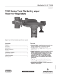
1
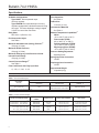
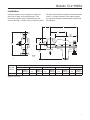
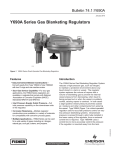
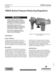
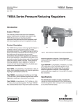
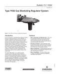
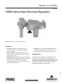
Bulletin 74.2:Y695A
January 2010
Y695A Series Vapor Recovery Regulators
W7381
Figure 1. Y695A Series Vapor Recovery Regulators
Features
• Simplicity—Direct-operated, straightforward stem
and lever design minimizes the number of parts
while providing excellent regulation of pressure.
• Easy Conversion—Changes easily from the
Type Y695A to the Type Y695AM with two O-rings
and a machine screw.
Introduction
• Rugged Construction—Heavy duty casings and
internal parts are designed to reduce vibration and
shock and give this regulator the ability to
withstand 150 psig (10,3 bar) inlet pressure with
no internal parts damage.
The Y695A Series are direct-operated vapor recovery
regulators. These regulators are used to sense an
increase in vessel pressure and vent excessive internal
tank pressure to an appropriate vapor recovery disposal
or reclamation system. They may also be used as
backpressure regulators or relief valves.
D102595X012
• Precision Control—Large diaphragm area
provides very accurate throttling control at low
pressure settings.
www.fisherregulators.com
Bulletin 74.2:Y695A
Specifications
Available Configurations
Flow Capacities
Type Y695A: Direct-operated vapor
recovery regulator.
Type Y695AM: Direct-operated vapor recovery regulator equipped with a blocked throat and O-ring stem seal. The lower diaphragm casing is tapped 1/2 NPT for control line connection.
See Table 4
Orifice Size
7/16-inch (11 mm)
Construction Materials
See Table 3
Body Sizes
Material Temperature Capabilities(1)
Nitrile:
-20° to 180°F (-29° to 82°C)
Fluorocarbon (FKM):
40° to 300°F (4° to 149°C)
Perfluoroelastomer (FFKM):
-20° to 300°F (-29° to 149°C)
Ethylenepropylene (EPDM):
-20° to 300°F (-29° to 149°C)
NPS 3/4 or 1 (DN 20 or 25)
End Connection Styles
See Table 1
Maximum Allowable Inlet (Casing) Pressure(1)
150 psig (10,3 bar)
Maximum Outlet Pressure(1)
150 psig (10,3 bar)
Maximum Emergency Inlet Pressure to Avoid
Internal Parts Damage
150 psig (10,3 bar)
Adjusting Screw
Spring Case Vent Connection
1/4 NPT
Diaphragm Case Connection
See Table 2
Flow Coefficients with Fully Open Disk
Control Pressure Ranges(1)
Pressure Setting Adjustment
Cg: 120, CV: 3.43, C1: 35
1/2 NPT
Approximate Weight
19 pounds (9 kg)
1. The pressure/temperature limits in this bulletin and any applicable standard or code limitation should not be exceeded.
Table 1. End Connection Styles
END CONNECTION STYLES(1)
BODY SIZES,
NPS (DN)
Ductile Iron
CF8M
Stainless Steel
Hastelloy® C
3/4 or 1 (20 or 25)
NPT
NPT, ANSI Class 150 RF,
ANSI Class 300 RF, or PN 16/25/40
ANSI Class 150 RF
1. All flanges have 14-inches (356 mm) face-to-face.
Table 2. Control Pressure Ranges
SPRING PART
NUMBER
SPRING COLOR
SPRING WIRE DIAMETER
2 to 7-inches w.c. (5 to 17 mbar)(1)(2)
3 to 13-inches w.c. (7 to 32 mbar)(1)(2)
10 to 26-inches w.c. (25 to 65 mbar)
1B653827052
1B653927022
1B537027052
Red
Olive drab
Yellow
0.085-inch (2,2 mm)
0.105-inch (2,7 mm)
0.114-inch (2,9 mm)
3.625-inches (92,1 mm)
3.75-inches (95,2 mm)
4.188-inches (106 mm)
0.9 to 2.5 psig (0,06 to 0,17 bar)
1.3 to 4.5 psig (0,09 to 0,31 bar)
3.8 to 7 psig (0,26 to 0,48 bar)
1B537127022
1B537227022
1B537327052
Light green
Light blue
Black
0.156-inch (4,0 mm)
0.187-inch (4,8 mm)
0.218-inch (5,5 mm)
4.060-inches (103 mm)
3.938-inches (100 mm)
3.980-inches (101 mm)
RELIEF SET PRESSURE RANGE
1. Spring ranges based on spring case installed pointed down. When installed pointing up, the spring ranges increase by 2-inches w.c. (5 mbar).
2. Do not use Fluorocarbon (FKM) diaphragm with these springs at diaphragm temperatures lower than 60°F (16°C).
2
FREE LENGTH
Bulletin 74.2:Y695A
Table 3. Construction Materials
BODY
Ductile iron,
CF8M Stainless steel,
or Hastelloy C
SPRING CASE
Ductile iron or
CF8M Stainless
steel
DIAPHRAGM CASE
DISK HOLDER
Ductile iron,
CF8M Stainless steel, or
Hastelloy C
316 Stainless steel
or Hastelloy C
DIAPHRAGM
DISK
Nitrile (NBR),
Fluorocarbon (FKM), or
Nitrile (NBR) with bonded
Teflon (PTFE)
Nitrile (NBR),
Fluorocarbon (FKM),
Perfluoroelastomer (FFKM),
Teflon (PTFE), or
Ethylenepropylene (EPDM)
Table 4. Y695A Series Capacities
MINIMUM BUILDUP TO
WIDE-OPEN
2-inches w.c.
(5 mbar)
1.5-inches w.c.
(3,7 mbar)
0 psig (0 bar)
2.5 psig (0,17 bar)
5 psig (0,34 bar)
280 (7,50)
1180 (31,6)
1520 (40,7)
4-inches w.c.
(10 mbar)
1.5-inches w.c.
(3,7 mbar)
0 psig (0 bar)
2.5 psig (0,17 bar)
5 psig (0,34 bar)
350 (9,38)
1200 (32,2)
1530 (41,0)
3 to 13-inches w.c. (7 to 32 mbar)
1B653927022
Olive drab
10-inches w.c.
(25 mbar)
2.3-inches w.c.
(5,7 mbar)
0 psig (0 bar)
2.5 psig (0,17 bar)
5 psig (0,34 bar)
520 (13,9)
1250 (33,5)
1570 (42,1)
10 to 26-inches w.c. (25 to 65 mbar)
1B537027052
Yellow
15-inches w.c.
(37 mbar)
3.4-inches w.c.
(8,5 mbar)
0 psig (0 bar)
2.5 psig (0,17 bar)
5 psig (0,34 bar)
640 (17,2)
1300 (34,8)
1600 (42,9)
1 psig
(0,07 bar)
0.40 psig
(0,03 bar)
0 psig (0 bar)
2.5 psig (0,17 bar)
5 psig (0,34 bar)
940 (25,2)
1450 (38,9)
1720 (46,1)
1360 (36,4)
1730 (46,4)
1940 (52,0)
0.9 to 2.5 psig (0,06 to 0,17 bar)
1B537127022
Light green
January 2010
1.3 to 4.5 psig (0,09 to 0,31 bar)
1B537227022
Light blue
2 psig
(0,14 bar)
0.88 psig
(0,06 bar)
0 psig (0 bar)
2.5 psig (0,17 bar)
5 psig (0,34 bar)
3.8 to 7 psig (0,26 to 0,48 bar)
1B537327052
Black
5 psig
(0,34 bar)
1.66 psig
(0,11 bar)
0 psig (0 bar)
2.5 psig (0,17 bar)
5 psig (0,34 bar)
Type Y695A
January 2010
Type Y695A
B2648
INLET PRESSURE
INLET
PRESSURE
OUTLET PRESSURE
OUTLET
PRESSURE
ATMOSPHERIC PRESSURE
ATMOSPHERIC
PRESSURE
INLET PRESSURE
FigurePRESSURE
2. Y695A Series
OUTLET
ATMOSPHERIC PRESSURE
Type Y695A
Type
Y695A
2110 (56,5)
2330 (62,4)
2470 (66,2)
MXXXX
2 to 7-inches w.c. (5 to 17 mbar)
1B653827052
Red
VACUUM OUTLET
PRESSURE
CAPACITIES IN
SCFH (Nm3/h) OF 0.97
SPECIFIC GRAVITY NITROGEN
SET PRESSURE
MXXXX
SPRING RANGE,
PART NUMBER, and COLOR
Operational Schematic
3
Bulletin 74.2:Y695A
Table 5. Materials Compatibility
CORROSION INFORMATION
Monel®(1)
Hastelloy® C(2)
Hastelloy® C(2)
S41600
Stainless Steel
Monel® (1)
CF8M or S31600
Stainless Steel
S41600
Stainless Steel
C
C
A
A
A
B
A
A
A
A
B
A
A
A
A
C
C
A
A
A
B
A
A
A
A
A
A
A
A
A
Hydrochloric Acid (Air free)
Hydrogen
Hydrogen Peroxide
Hydrogen Sulfide (Liquid)
Magnesium Hydroxide
Aluminum Sulfate
Ammonia
Ammonium Chloride
Ammonium Nitrate
Ammonium Sulfate
C
A
C
A
C
C
A
C
C
C
A
A
B
A
B
A
A
B
A
A
C
A
C
C
C
B
A
B
C
A
A
A
A
A
A
Methanol
Methyl Ethyl Ketone
Natural Gas
Nitric Acid
Petroleum Oils (Refined)
Ammonium Sulfite
Beer
Benzene (Benzol)
Benzoic Acid
Boric Acid
C
B
A
C
C
C
B
A
C
C
A
A
A
A
A
A
A
A
A
A
B
B
A
A
B
C
A
A
A
A
A
A
A
A
A
Butane
Calcium Chloride (Alkaline)
Carbon Dioxide (Dry)
Carbon Dioxide (Wet)
Carbon Disulfide
A
B
A
C
A
A
B
A
C
A
A
C
A
A
A
A
B
A
A
A
A
C
A
A
B
A
A
A
A
B
B
C
A
C
C
B
C
A
C
C
B
B
B
C
C
B
B
B
C
C
C
A
C
C
C
Chromic Acid
Citric Acid
Coke Oven Gas
Copper Sulfate
Ether
C
I.L.
A
C
B
C
C
A
C
B
C
B
A
B
A
B
A
A
B
A
Ethyl Chloride
Ethylene
Ethylene Glycol
Formaldehyde
Formic Acid
C
A
A
B
I.L.
C
A
A
B
C
A
A
A
A
B
B
B
A
A
C
B
B
A
A
C
B
A
A
A
C
Freon (Wet)
Freon (Dry)
Gasoline (Refined)
Glucose
Hydrochloric Acid (Aerated)
S30200 or S30400
Stainless Steel
CF8M or S31600
Stainless Steel
C
C
A
A
A
Carbon Tetrachloride
Carbonic Acid
Chlorine Gas (Dry)
Chlorine Gas (Wet)
Chlorine (Liquid)
Cast or
Ductile Iron
S30200 or S30400
Stainless Steel
Acetic Acid (Air Free)
Acetic Acid Vapors
Acetone
Acetylene
Alcohols
Fluid
Carbon Steel
Cast or
Ductile Iron
Material
Carbon Steel
Material
C
A
I.L.
C
A
C
A
A
C
A
C
A
A
A
A
C
A
A
A
A
C
A
B
C
A
C
A
A
C
A
B
A
B
A
A
A
A
A
C
A
A
A
A
C
A
A
A
A
A
A
A
A
A
B
A
A
A
A
C
A
A
A
A
C
A
A
A
A
B
A
Phosphoric Acid (Air Free)
Phosphoric Acid Vapors
Potassium Chloride
Potassium Hydroxide
Propane
C
C
B
B
A
C
C
B
B
A
A
B
A
A
A
A
A
A
B
A
C
C
C
B
A
B
C
B
A
A
A
I.L.
A
A
A
A
A
A
A
A
Silver Nitrate
Sodium Acetate
Sodium Carbonate
Sodium Chloride
Sodium Chromate
C
A
A
C
A
C
A
A
C
A
A
B
A
B
A
A
A
A
B
A
B
A
B
B
A
C
A
A
A
A
A
A
A
A
A
A
A
A
C
C
A
A
A
B
A
Sodium Hydroxide
Stearic Acid
Sulfur
Sulfur Dioxide (Dry)
Sulfur Trioxide (Dry)
A
A
A
A
A
A
C
A
A
A
A
A
A
A
A
A
A
A
A
A
B
B
A
B
B
A
B
A
A
A
A
A
A
A
A
C
B
A
A
A
A
B
B
C
A
A
A
A
A
A
Sulfuric Acid (Aerated)
Sulfuric Acid (Air Free)
Sulfurous Acid
Trichloroethylene
Water (Boiler Feed)
C
C
C
B
B
C
C
C
B
C
C
C
B
B
A
C
C
B
A
A
C
C
C
B
B
C
B
C
A
A
A
A
A
A
A
A
A
A
A
B
B
A
A
A
C
A
A
A
A
A
A
A
I.L.
A
A
Water (Distilled)
Water (Sea)
Zinc Chloride
Zinc Sulfate
A
B
C
C
A
B
C
C
A
B
C
A
A
B
C
A
B
C
C
B
A
A
C
A
A
A
A
A
A
A
A
A
C
I.L.
I.L.
A
A
C
A
A
A
A
C
A
A
A
A
B
1. Monel is a trademark of International Nickel Co.
2. Hastelloy is a trademark of Stelite Div., Cabot Corp.
Fluid
----
---- ---- ---- ---- ---- ---- ----
A+--Best possible selection
A--Recommended
B--Minor to moderate effect. Proceed with caution.
C--Unsatisfactory
I.L.--Information lacking
- continued -
Principle of Operation
Y695A Series vapor recovery regulators are used to
maintain a constant blanket (inlet) pressure or vessel
pressure with the outlet flowing to a system whose
pressure is lower than the inlet (see Figure 2).
4
When vessel pressure increases above the setpoint
of the regulator due to pumping in or thermal heating,
the force of the control spring is overcome by pressure
acting on the diaphragm. This moves the disk away
from the orifice, allowing gas to flow from the vessel
to the vapor recovery system. As vessel pressure is
Bulletin 74.2:Y695A
Table 5. Materials Compatibility (continued)
FLUID INFORMATION
Material
Fluid
Neoprene
(CR)
Nitrile
(NBR)
Fluorocarbon
(FKM)
Perfluoroelastomer
(FFKM)
Ethylenepropylene
(EPDM)
c
b
a
a+
A
B
C
A
A
C
B
C
B
C
C
A
A
A
A
A
A
A
A
A
A
B
C
A
B
A
B
C
C
A
C
A+
A
C
A
B
B
A
A
A
A
A
A
A
A
B
C
A
C
C
C
Carbon Tetrachloride
Chlorine (Dry)
Chlorine (Wet)
Coke Oven Gas
Ethyl Acetate
C
C
C
C
C
C
C
C
B
C
A
A
A
A+
C
A
A
A
A
A
C
C
C
C
B
Ethylene Glycol
Freon 11
Freon 12
Freon 22
Freon 114
A
B
A+
A+
A
A
A
A
C
A
A
A+
B
C
B
A
A
A
A
A
A
C
B
A
A
Gasoline
Hydrogen Gas
Hydrogen Sulfide (Dry)
Hydrogen Sulfide (Wet)
Jet Fuel (JP-4)
B
A
A
B
C
A+
A
C
C
A
A
A
C
C
A
A
A
A
A
A
C
A
A
A
I.L.
Natural Gas
Natural Gas + H2S (Sour Gas)
Nitric Acid (20%)
Nitric Acid (50 to 100%)
Nitrogen
A
A
B
C
A
A+
B
C
C
A
A
C
A
A
A
A
A
A
A
A
C
C
C
C
A
Oil (Fuel)
Propane
Sulfur Dioxide
Sulfuric Acid (to 50%)
Sulfuric Acid (50 to 100%)
B
A
B
A
B
A+
A
A
C
C
A
A
A
A
A
A
A
A
A
A
C
C
A
A
B
Water (Ambient)
Water [at 200°F (93°C)]
Water (Sea)
C
A
C
C
A
B
A
A
B
A
A
A
B
A
A
Acetic Acid (30%)
Acetone
Alcohol (Ethyl)
Alcohol (Methyl)
Ammonia (Anhydrous)
Ammonia (Gas, Hot)
Benzene
Brine (Calcium Chloride)
Butadiene Gas
Butane (Gas)
Butane (Liquid)
A+--Best possible selection
A--Recommended
B--Minor to moderate effect. Proceed with caution.
C--Unsatisfactory
I.L.--Information lacking
reduced, the force of the back disk spring causes the
disk to move toward the orifice, decreasing the flow of
gas out of the vessel. As vessel pressure drops below
the setpoint of the regulator, the disk will seat against
the orifice, shutting off the flow of gas.
Sizing Vapor Recovery Systems
To determine the capacity required, you must consider
the amount of blanketing gas that must be displaced
from the tank when either filling the vessel with liquid
(pump-in) or the expansion of tank vapors during
atmospheric thermal heating.
Using the established procedures from American
Petroleum Institute Standard 2000 (API 2000),
determine the required flow rate for outbreathing.
For liquids with a flash point below 100°F (38°C) or a
normal boiling point below 300°F (149°C), multiply the
calculated outbreathing requirements in Table 6 by 2.0
as indicated in footnote 1 from Table 6.
5
Bulletin 74.2:Y695A
Table 6. Flow Rate Conversions (Gas flow required to displace
blanketing gas with pump-in of liquid.)
MULTIPLY MAXIMUM
PUMP RATE IN
BY
TO OBTAIN
U.S. GPM
U.S. GPH
Barrels/hour
Barrels/day
8.021
0.1337
5.615
0.2340
SCFH air
required(1)(2)
1. For liquids with a flash point below 100°F (38°C) or normal boiling point below 300°F
(149°C), multiply the above calculated outbreathing requirement by 2.0.
2. To convert to Nm³/h multiply scfh by 0.0268.
1. Determine the flow rate of blanketing gas displaced
when liquid is being pumped in (see Table 6).
2. Determine the gas flow rate due to “outbreathing”
caused by atmospheric thermal heating (see
Table 7).
3. Add the requirements of steps 1 and 2 and select
a vapor recovery regulator size based on total
capacity required from Table 4.
Sample sizing problem for vapor
recovery applications:
Vessel capacity . . . . . . 1000 barrels (42,000 gal)(159 000 liters)
Pump in capacity . . . . . . . . . . . . . . . . . 20 GPM (75,7 l/min)
Inlet pressure source . . . . . . . . 60 psig (4,14 bar) nitrogen
Desired blanket setpoint . . . . . . . . 0.5-inches w.c. (1 mbar)
Desired vapor recovery setpoint . . . 2-inches w.c. (5 mbar)
Vapor recovery vacuum source . . . 5-inches Hg (169 mbar)
Fluid . . . . . . . . . . . . . . . . . . . . . . . . . . . . . . . . . . . . . Hexane
Boiling point . . . . . . . . . . . . . . . . . . . . . . . . . . 155°F (68°C)
1. From Table 6 the desired air flow rate due to pump
in equals 20 gpm (75,7 l/min) x 8.021 x 2 = 321
scfh (8,60 Nm3/h) air.
2. From Table 7 the desired air flow rate = 1000 scfh
(26,8 Nm3/h) air due to thermal heating.
3. Total required flow rate = 1000 scfh (26,8 Nm3/h)
air + 320 scfh (8,58 Nm3/h) = 1320 scfh
(35,4 Nm3/h) air. This converts to nitrogen
requirements of 1340 scfh (35,9 Nm3/h).
Capacity Information
Table 4 gives typical nitrogen regulating capacities at
selected inlet pressures and outlet pressure settings.
Flows are in scfh at 60°F and 14.7 psia and Nm³/h at
0°C and 1,01325 bar of 0.97 specific gravity nitrogen.
For gases of other specific gravities, multiply the
6
Table 7. Gas Flow Required for Thermal Heating (Outbreathing)
per API 2000 (Interpolate for intermediate sizes.)
VESSEL CAPACITY
Barrels
Gallons
Liters
60
100
500
1000
2000
2500
4200
21,000
42,000
84,000
9500
15 000
79 500
159 000
318 000
3000
4000
5000
10,000
15,000
126,000
168,000
210,000
420,000
630,000
20,000
25,000
30,000
35,000
40,000
SCFH (Nm³/h) AIR FLOW
RATE REQUIRED
Flash point is equal Flash point is
to or above 100°F
below 100°F
(38°C) or normal
(38°C) or
boiling point is
normal boiling
equal to or above
point is below
300°F (149°C)
300°F (149°C)
40 (1,07)
60 (1,61)
300 (8,04)
600 (16,1)
1200 (32,2)
60 (1,61)
100 (2,68)
500 (13,4)
1000 (26,8)
2000 (53,6)
477 000
636 000
795 000
1 590 000
2 385 000
1800
2400
3000
6000
9000
3000 (80,4)
4000 (107)
5000 (134)
10,000 (268)
15,000 (402)
840,000
1,050,000
1,260,000
1,470,000
1,680,000
3 180 000
3 975 000
4 769 000
5 564 000
6 359 000
12,000
15,000
17,000
19,000
21,000
(322)
(402)
(456)
(509)
(563)
20,000
24,000
28,000
31,000
34,000
45,000
50,000
60,000
70,000
80,000
1,890,000
2,100,000
2,520,000
2,940,000
3,360,000
7 154 000
7 949 000
9 539 000
11 129 000
12 718 000
23,000
24,000
27,000
29,000
31,000
(616)
(643)
(724)
(777)
(831)
37,000 (992)
40,000 (1072)
44,000 (1179)
48,000 (1286)
52,000 (1394)
90,000
100,000
120,000
140,000
160,000
3,780,000
4,200,000
5,040,000
5,880,000
6,720,000
14 308 000
15 898 000
19 078 000
22 257 000
25 437 000
34,000 (911)
36,000 (965)
41,000 (1099)
45,000 (1206)
50,000 (1340)
56,000
60,000
68,000
75,000
82,000
180,000
7,560,000
28 616 000
54,000 (1447)
90,000 (2412)
(48,2)
(64,3)
(80,4)
(161)
(241)
(536)
(643)
(750)
(831)
(911)
(1501)
(1608)
(1822)
(2010)
(2198)
given capacity of nitrogen by 0.985, and divide by the
square root of the appropriate specific gravity of the
gas required. To determine regulating capacities at
pressure settings not given or to determine wide-open
flow capacities, use the following formula:
Q=
3417
520
CgP1SIN
C1
GT
∆P
P1
Deg.
Where:
  Cg = gas sizing coefficient from Specifications
  C1 = Cg/Cv or 35 from Specifications
  G = gas specific gravity (air = 1.0)
P1abs = inlet pressure, psia (add 14.7 psi to gauge inlet
pressure to obtain absolute inlet pressure)
  Q = flow rate, scfh
  T = absolute temperature in °Rankine of gas at inlet
(°Rankine = °F + 460)
  ∆P = Pressure differential across the valve,
psig (P1 - P2)
Bulletin 74.2:Y695A
Installation
full flow valve between the regulator and the blanketed
vessel. For proper operation at low setpoint ranges,
the regulators should be installed with the spring case
pointed down.
Install the regulator using a straight run of pipe the
same size or larger as the regulator body. Flow
through the regulator body is indicated by the flow
arrow on the body. If a block valve is required, install a
G
F
D
8.38
(213)
DIAMETER
B
14
(356)
A
5.56
(141)
INCHES
(mm)
B2441
DIMENSIONS, INCHES (mm)
BODY SIZE,
NPS (DN)
3/4,1 (20, 25)
A
B
Iron
Stainless
Steel or
Hastelloy® C
4.0 (102)
4.12 (105)
D
Ductile
Iron
Stainless
Steel or
Hastelloy® C
2.12 (54)
2.25 (57)
F
Ductile
Iron
Stainless
Steel or
Hastelloy® C
6.19 (157)
6.19 (157)
G
Ductile
Iron
Stainless
Steel or
Hastelloy® C
Ductile
Iron
Stainless
Steel or
Hastelloy® C
10.38 (264)
10.38 (264)
1.69 (43)
1.69 (43)
Figure 3. Dimensions
7
Bulletin 74.2:Y695A
Ordering information
5. Flow rates
a) Minimum controlled flow
b) Normal flow
c) Maximum flow
6. Line size and end connection size of adjacent piping.
When ordering, specify:
Application
1. Type of gas being controlled (natural gas, air, etc.);
list any factors such as impurities in the gas that
may affect compatibility of gas with the regulator
trim parts.
2. Specific gravity of the gas.
3. Temperature of the gas.
4. Range of flowing inlet pressures to regulator.
Regulator
Refer to the Specifications table on page 2. Carefully
review the description of each specification and make
the desired selection wherever there is a choice.
Always specify the type number.
Industrial Regulators
Natural Gas Technologies
TESCOM
Emerson Process Management
Regulator Technologies, Inc.
Emerson Process Management
Regulator Technologies, Inc.
Emerson Process Management
Tescom Corporation
USA - Headquarters
McKinney, Texas 75069-1872 USA
Tel: 1-800-558-5853
Outside U.S. 1-972-548-3574
USA - Headquarters
McKinney, Texas 75069-1872 USA
Tel: 1-800-558-5853
Outside U.S. 1-972-548-3574
USA - Headquarters
Elk River, Minnesota 55330-2445 USA
Tel: 1-763-241-3238
Asia-Pacific
Shanghai, China 201206
Tel: +86 21 2892 9000
Asia-Pacific
Singapore, Singapore 128461
Tel: +65 6777 8211
Europe
Bologna, Italy 40013
Tel: +39 051 4190611
Europe
Bologna, Italy 40013
Tel: +39 051 4190611
Gallardon, France 28320
Tel: +33 (0)2 37 33 47 00
Middle East and Africa
Dubai, United Arab Emirates
Tel: +971 4811 8100
Europe
Selmsdorf, Germany 23923
Tel: +49 (0) 38823 31 0
For further information visit www.fisherregulators.com
The Emerson logo is a trademark and service mark of Emerson Electric Co. All other marks are the property of their prospective owners. Fisher is a mark owned by Fisher Controls, Inc., a
business of Emerson Process Management.
The contents of this publication are presented for informational purposes only, and while every effort has been made to ensure their accuracy, they are not to be construed as warranties or
guarantees, express or implied, regarding the products or services described herein or their use or applicability. We reserve the right to modify or improve the designs or specifications of such
products at any time without notice.
Emerson Process Management does not assume responsibility for the selection, use or maintenance of any product. Responsibility for proper selection, use and maintenance of any Emerson
Process Management product remains solely with the purchaser.
©Emerson Process Management Regulator Technologies, Inc., 1999, 2010; All Rights Reserved