1
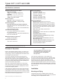
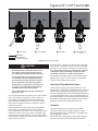
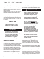
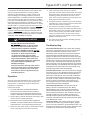
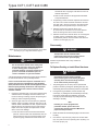
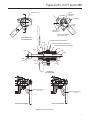
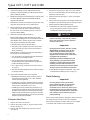
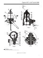
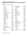
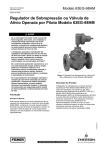
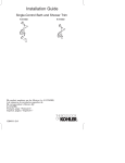
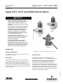
Instruction Manual
MCK-2287
Types C471, C477 and C486
September 2014
Types C471, C477 and C486 Internal Valves
!
WARNING
Failure to follow these instructions or to
properly install and maintain this equipment
could result in an explosion and/or fire
causing property damage and personal injury
or death.
Fisher® equipment must be installed, operated
and maintained in accordance with federal,
state and local codes and Emerson Process
Management Regulator Technologies, Inc.
(Emerson™) instructions. The installation
in most states must also comply with NFPA
No. 58 and ANSI Standard K61.1.
Only personnel trained in the proper
procedures, codes, standards and regulations
of the LP-Gas industry should install and
service this equipment.
TYPE C471
P1197
TYPE C477
The internal valve must be closed except
during product transfer. A line break
downstream of a pump may not actuate the
excess flow valve. If any break occurs in the
system or if the excess flow valve closes, the
system should be shut down immediately.
TYPE C486
Introduction
Figure 1. C471, C477 and C486 Series Internal Valves
Scope of the Manual
Specifications
Description
The Specifications section on the following page shows
specifications for Types C471, C477 and C486 internal valves.
The valves are typically used on the inlets and outlets of
bobtail and transport trucks and on large stationary storage
tanks. They can also be installed in-line. Designed for
propane, butane or NH3 at ambient temperatures, the valves
can be used on other compressed gases, but the user should
check with the factory to make sure the valves are suitable for
the particular service.
DOT Internal Self-Closing Stop Valve Requirement—
U.S. Department of Transportation (DOT) regulations
49CFR§178.337-8(a)(4) require each liquid or vapor
discharge outlet on cargo tanks (except for cargo tanks used
to transport chlorine, carbon dioxide, refrigerated liquid and
certain cargo tanks certified prior to January 1, 1995) to be
fitted with an internal self-closing stop valve. Fisher “C” Series
internal valves comply with the internal self-closing stop valve
requirement under the DOT regulations.
D450229T012
This manual covers instructions for the Types C471, C477
and C486 internal valves.
www.fisherregulators.com
Types C471, C477 and C486
Specifications (continued)
Body Size and End Connection Styles
Types C471 and C477
Inlet: 2 or 3-inch MNPT / DN 50 or 80
Outlet: 2 or 3-inch FNPT / DN 50 or 80
Type C486
Inlet: 3-inch CL300 RF Flange / DN 80
Outlet: 3-inch FNPT / DN 80
Number of Outlets
Type C471: 2 (side and straight through)
Types C477 and C486: 1 (straight through)
Excess Flow Springs
Type C470 Half Coupling and Type C486 Flows:
2-inch Sizes / DN 50: 105, 150 and 250 GPM / 397, 567 and 946 L/min
3-inch Sizes / DN 80: 160, 265, 375 and 460 GPM / 605, 1003, 1419 and 1741 L/min
Type C470 Full Coupling Flows: 2-inch Sizes / DN 50: 60, 80 and 130 GPM /
227, 302 and 492 L/min
3-inch Sizes / DN 80: 120, 230, 320 and 380 GPM / 454,
870, 1211 and 1438 L/min
Maximum Allowable Inlet Pressure(1)
400 psig / 27.6 bar WOG
Temperature Capabilities(1)(2)
-20 to 150°F / -29 to 66°C
Approximate Weights
2-inch Sizes / DN 50:
Type C471: 11 pounds / 5.0 kg
Type C477: 9 pounds / 4.1 kg
3-inch Sizes / DN 80:
Type C471: 21 pounds / 10 kg
Type C477: 16 pounds / 7.3 kg
Type C486: 20 pounds / 9.1 kg
Construction Materials
Ductile Iron: Body (Types C471 and C477)
Stainless steel: Stem Assembly, Excess Flow Spring, Spring Seat, Closing Spring, Disc Holder, Disc Retainer, Screw, O-ring Seat, O-ring Retainer, Cotter Pin, Spring, Shaft, Screen, Travel Stop, Screen Cap, Bolt, Gasket and Lock Washer
Steel: Body (Type C486), Cap Screw and
Operating Lever
Plated steel: Nut, Washer, Bonnet Nut, Guide Bracket and Cap Screw
Polyurethane (PU): Rod Wiper
Polytetrafluoroethylene (PTFE): Bushing, Packing Adaptor and Packing Ring
Nitrile (NBR) (Standard Construction): Main Disc, Bleed Disc and O-ring
Other Disc Material Available from Factory: PTFE,
Fluorocarbon (FKM), Neoprene (CR), Ethylene-
Propylene (EPDM) and Kalrez®
1. The pressure/temperature limits in this Instruction Manual and any applicable standard or code limitation should not be exceeded.
2. Product has passed Fisher® testing for leakage down to -40ºF / -40ºC.
Principle of Operation
Refer to the schematic drawing, Figure 2. In view #1, the
valve is held closed by both tank pressure and the valve’s
closing spring. There is no leakage past the resilient seats
in the poppet to the valve outlet.
The valve is opened by moving the operating lever to
approximately mid-point in its 70° travel (view #2). This
allows the cam to place the rapid equalization portion of the
valve stem in the pilot opening, permitting a larger amount
of product to bleed downstream than if the operating lever
were moved to the full open position.
When tank and downstream pressure are nearly equal
after a few seconds, the excess flow spring pushes open
the main poppet (view #3) and the operating lever can be
moved to the full open position.
If tank pressure is greater than the valve’s outlet pressure,
the main poppet will remain in the closed position. If valve
outlet piping is closed off by other valves, however, product
bleeding through the pilot will increase until it nearly equals
tank pressure and the main poppet opens.
Kalrez® is a mark owned by E.I. du Pont de Nemours and Co.
2
Note
The main poppet will not open if valve
outlet piping is not closed off so that
the outlet pressure can approach
tank pressure.
Once the main poppet opens, a flow greater than
the valve’s excess flow spring rating or a sufficient surge
in flow forces the main poppet closed against the excess
flow spring (view #4). The pilot valve allows a small
amount of product to bleed, but much less than view #2
where the rapid equalization portion of the stem is placed
in the pilot opening. When the operating lever is moved to
the closed position, the valve closes completely and seals
tightly (view #1).
Installation
Mounting and Piping
The internal valves can be installed in either a half or full
coupling. Excess flow spring closing flow rates vary in half and
full couplings, refer to the Specification section.
Types C471, C477 and C486
1
JET
BLEED
JET
BLEED
2
JET BLEED OPEN
VALVE CLOSED
FLOW
FLOW
3
VALVE OPEN
M1170
LIMITED
BLEED
4
LIMITED
BLEED
EXCESS FLOW VALVE
CLOSED
LIMITED BLEED
VALVE OPEN FLOW
JET BLEED EQUALIZATION
Figure 2. Operational Schematic
Excess flow valve closing flow rates are not
the same for half and full couplings. Verify
the coupling for the desired excess flow rate.
The valves have a break off section below the inlet pipe
thread which is intended to permit the lower valve body
to shear off in an accident, leaving the valve seat in the
tank. The break off section is designed for container
installations and will probably not provide shear
protection if the valve is installed in a pipeline.
Do not install the valve in any piping tending
to restrict the valve inlet because this may
prevent the excess flow valve from closing.
A hydrostatic relief valve does not need to be installed
adjacent to the valve since the internal valve relieves
excessive line pressure into the tank.
CAUTION
Do not install the valve with such extreme
torque that the coupling can cut threads into
the valve. This could cause valve distortion
and affect the internal working parts.
Do not use PTFE tape as it may cause thread
galling to occur.
Use an appropriate pipe compound, on the male threads
of the internal valve and pipeline. Pull the valve into
the coupling hand tight and then wrench tighten it for
approximately two additional turns. Larger size valves
may require an additional amount of torque to obtain a
leak-free connection.
Keep piping from the valve outlet to the pump full size
and as short as possible with a minimum number of
bends. Reduction in pipe size to suit smaller pump inlets
should be made as close to the pump as possible using
forged reducers (swage nipples) or venturi tapers rather
than bushings. This assures minimum flow resistance and
efficient pump operation.
Selectively Filling Manifolded Tanks
Fisher® internal valves provide positive shutoff only in one
direction, from out of the tank to downstream of the valve. The
internal valves are designed to allow gas to flow into a tank
when the downstream line pressure exceeds tank pressure. If
you want to selectively fill one or more of the other tanks in a
tank manifold system, you must place a positive shutoff valve
downstream of the internal valve, otherwise, all tanks will be
filled at the same time and at about the same rate.
Actuators
The remote operating control system for the valve is
extremely important and it must be installed to conform
with the applicable codes. DOT MC331, for example, most
generally applies for trucks.
Fisher offers both cable controls and pneumatic actuator
systems to operate the C470 and C486 Series internal
3
Types C471, C477 and C486
valves. It may also be possible to use cable controls from
other manufacturers or to fabricate a linkage mechanism.
Any control system requires thermal protection (fuse
links) at the valve, at the remote control point and, if
necessary, near the hose connections. The Instruction
Manuals for Emerson™ actuator systems show how to
install the fuse links.
Installation instructions on Fisher® Types P650, P163A and
P164A cable controls, are in Document D450012T012.
Pneumatic actuator installation is covered in Document
D450162T012. Type P340 latch/remote release instructions
are on Document D450123T012.
The operating linkage must allow the operating lever to
move from the fully closed position to within 2° of the fully
open position. The linkage should not apply strong force
to the lever past the fully open position or the valve could
be damaged.
Warranty Note
The use of non-Fisher actuators will void
internal valve warranty and may result in
leakage of the gland packing caused by
premature wear. In addition to premature
wear, the use of non- Fisher actuators may
result in lower than expected flow rates and
possible leakage across the valve seats.
CAUTION
The internal valve’s closing spring is not
designed to overcome drag in the control
linkage in order to close the valve. Depending
upon the control system used, an external
spring (such as Fisher drawing number
1K4434) or positive closing linkage may
be needed. Be sure the control system
is installed to prevent binding that could
cause the valve to stick in the open position.
Excess Flow Operation
The internal valve contains an excess flow function or
“integral excess flow valve”, that will close when the flow
exceeds the flow rating established by Fisher. Fisher integral
excess flow valve installed on a bobtail truck or transport
can provide protection against the discharge of hazardous
materials during an unloading operation of a bobtail truck or
transport in the event that a pump or piping attached directly
to the internal valve is sheared off before the first valve,
pump or fitting downstream of the internal valve, provided
that the cargo tank pressure produces a flow rate greater
than the valve’s excess flow rating.
Likewise, if the internal valve is installed on a stationary
tank or in the related downstream piping system, the
integral excess flow valve can provide protection against an
unintentional release of hazardous materials in the event
4
that a pump or piping attached directly to the internal valve is
sheared off before the first valve, pump or fitting downstream
of the internal valve, provided that the flow of product through
the internal valve reaches the rated flow specified by Fisher.
!
EXPLOSION HAZARD
Restrictions incorporated in the discharge
system of a bobtail truck or transport or of
a stationary tank (due to pumps, pipe and
hose length and dimensions, branching,
elbows, reductions in pipe diameter or a
number of other in-line valves or fittings),
low operating pressure as a result of
ambient temperature or a partially closed
valve downstream from the integral excess
flow valve, can restrict the rate of flow
through the internal valve below the level
necessary to actuate the integral excess
flow valve. Therefore, DO NOT USE the
excess flow function of the internal valve for
the purpose of providing protection against
the discharge of hazardous materials in the
event of a rupture of hose or piping at a
point in the discharge system downstream
from the first valve, pump or fitting
downstream of the internal valve.
The internal valve is designed with an
internal bleed feature for equalization of
pressure. After the integral excess flow valve
closes, the leakage through the bleed must
be controlled or a hazard can be created. For
this reason the operator must be familiar with
the closure controls for the internal valve and
must close the internal valve immediately
after the integral excess flow valve closes.
Failure to follow this warning could result in
serious personal injury or property damage
from a fire or explosion.
DOT Passive Shutdown Equipment Requirement—DOT
regulations 49CFR§173.315(n)(2) require certain cargo
tanks transporting propane, anhydrous ammonia and
other liquefied compressed gases to be equipped with
passive emergency discharge control equipment that will
automatically shutoff the flow of product without human
intervention within 20 seconds of an unintentional release
caused by complete separation of a delivery hose. The design
for each passive shutdown system must be certified by a Design
Certifying Engineer (DCE) and all components of the discharge
system that are integral to the design must be included in the
DCE certification. The DCE certification must consider any
specifications of the original component manufacturer.
In the case of downstream ruptures in hose or piping, a
variety of operating conditions routinely encountered during
an unloading operation restrict the rate of flow through the
integral excess flow valve and make such a valve unsuitable
to serve as the means of passive shutdown required under
49CFR§173.315(n) (2). Such variables include restrictions
Types C471, C477 and C486
incorporated in the discharge system (due to pumps, pipe
and hose length and dimensions, branching, elbows,
reductions in pipe diameter or a number of other in-line
valves or fittings), low operating pressure as a result of
ambient temperature or a partially closed valve downstream
from the excess flow valve. Due to the variety of conditions,
in the case of a hose separation, that can restrict the rate of
flow below the level necessary to activate the excess flow
valve, the integral excess flow function of Fisher® “C” Series
internal valves or “F” Series excess flow valves cannot be
used to satisfy the passive shutdown equipment requirement
under/in 49CFR§173.315(n)(2). Also, a Design Certifying
Engineer cannot include the integral excess flow valve of
a Fisher “C” Series internal valve or “F” Series excess flow
valve as a component of the discharge system in any DCE
certification under 49CFR§173.315(n)(2).
!
EXPLOSION HAZARD
DO NOT USE the excess flow function
incorporated into Fisher “C” Series internal
valves or “F” Series excess flow valves to
satisfy the passive shutdown equipment
requirement in 49CFR§173.315(n)(2). DO NOT
include the excess flow function incorporated
into Fisher “C” Series internal valves or
“F” Series excess flow valves in a DCE
certification under 49CFR§173.315(n)(2). The
cargo tank manufacturer must install some
other equipment that satisfies the requirement
for passive shutdown capability under
49CFR§173.315(n)(2).
Failure to follow this warning could result in
serious personal injury or property damage
from a fire or explosion in the event of an
unintentional release of product during an
unloading operation.
Operation
Since the C470 and C486 Series will not open unless
the downstream pressure can build-up to equal the
inlet pressure, an operating sequence that assures
equalization is important.
Follow these points:
1. C470 and C486 Series on bobtails and transports
should never be open when the truck is in motion. If
the control system is not interlocked to prevent this, the
operator is responsible to see that the valves are closed.
2. Always open the internal valve before opening any other
valves in the line or starting the pump.
3. Move the lever to the half-open position (Operational
Schematic, view #2) to equalize pressure. When the main
poppet clicks open, move the operating lever fully open.
4. Open other line valves slowly to avoid sudden surges
which could slug the excess flow valve shut.
5. If the excess flow valve does close, stop the
pump and close the nearest downstream valve. Move
the internal valve’s operating lever back to the rapid
equalizing position and wait for the valve to click
open. Then move the operating lever fully open and
slowly open the downstream valve.
6. All valves should be completely open when pumping.
(Throttling type valves could prevent the excess flow
valve from closing when required.)
7. The operator must always be aware of where the
remote closure controls are located and know how to
operate the controls if an emergency requires valve
closure. When pumping is finished, make a habit of
closing the internal valve from the remote closure
point, thus checking to see that the control actually is
capable of closing the valve.
8. The valve should be open when backfilling through
the valve to fill the tank.
Troubleshooting
Internal Valve Will Not Open—This could be due to leakage
downstream, engaging the pump too soon or from excessive
wear in the internal valve. If excessive volume is in the
downstream system, a longer time is required to equalize the
pressures (tank and downstream) before the pump can be
engaged. To determine if the valve pilot seat is opening, install
a gauge downstream of the valve, operate the valve actuator; if
pressure does not build up to the tank pressure, the valve pilot
seat is not open. This test should be done with pump off. If the
pilot is not opening, it may be plugged with dirt or some internal
part may be broken. If by operating the lever manually it can be
rotated past the fully open position, there is something wrong
internally and the valve must be disassembled.
Premature Valve Closure—This can be caused from engaging
the pump too soon, by an underrated excess flow valve spring
or by an improperly connected internal valve operating lever
which does not fully open the valve. The trouble could also be
from a valve that has its inlet port obstructed or from sudden
line surges. In order to check the valve opening travel, operate
the lever manually to the full travel, wait until valve opens,
then engage the pump. If the excess flow closes, the points
mentioned above should be investigated.
Internal Valve Will Not Close—The stub shaft could be
binding or the stem could be bent in the valve. Before
disassembling the valve, check the actuator mechanism to
see that it operates freely by disconnecting it from the valve
lever and cycling it several times. Also, operate the valve lever
manually. If it sticks in the open position, the packing and
bushings should be replaced. This should free the operating
mechanism if the valve has not been damaged internally. Refer
to the “Maintenance” section.
Low Flow Capacity—This could be caused by too small an
internal valve, too small or long downstream piping, plugged
screens, some other restriction in the downstream system or by
the bypass valve sticking in the open position. The bypass valve
could also be set too low and be opening prematurely.
5
Types C471, C477 and C486
the internal valve. If piping is cold allow it to warm to
ambient temperature.
b. R
efer to CFR 49 Section 180 Appendix B for Meter
Creep Test Methods.
3. All operating controls should be inspected and cleaned
and oiled. The controls should be checked to see that
they fully open—but not over-travel—the internal valve
operating lever and operate freely to close the valve.
4. Standard construction internal valves must
be removed if the container is to be steam cleaned.
Heat can damage the valve’s seats and seals.
5. Standard construction internal valves are not designed
for water service. Immediately after a container is
hydrostatically tested, remove all water and allow the
container to thoroughly dry out.
Disassembly
Figure 3. Use Tool Provided or Spring Seat (key 4) and Stem
Assembly (key 2) to Align Disc Retainer (key 8)
!
WARNING
Tank pressure must be released before
removing the valve from the container. Failure
to do so could result in personal injury.
Maintenance
CAUTION
Do not use these internal valves if they leak,
fail to work properly or have been damaged
or have missing parts. Prompt repairs
should be made by a properly trained service
person. Continued use without repair can
create a hazardous or injurious situation.
A simple preventative maintenance program for the valve and
its controls will eliminate a lot of potential problems.
Fisher® recommends these steps be conducted once a
month. Also refer to the Department of Transportation
(DOT) CFR 49 Sections 180.416 and 180 Appendix A and
B which specify monthly maintenance and inspections
tests for cargo tank service internal valves and their
actuation controls.
Numbers in parenthesis refer to key numbers in
Figures 3 to 7.
To Replace Packing or Install Gland Hardware
!
WARNING
Downstream pressure must be released
before removing the screws holding the gland
assembly to the internal valve body. Failure to
do so could result in personal injury.
1. The packing (keys 15F, G and H) can be replaced with
product in the tank by closing the operating lever (key 18)
and blowing down the downstream pressure in the system.
1. Inspect the operating lever to see that it operates freely
and that there is no leakage around the retainer nut.
If there is sticking or leakage, replace the packing and
bushings. Refer to Replacing Packing.
2. If using Screw-Type hardware, remove the three cap
screws (key 17) holding the bonnet assembly to the body.
If using the current Stud-Type hardware, remove the
nuts (key 59) and washers (key 55) holding the bonnet
assembly to the body.
2. Check for tight closure of the seat discs. Any detected
leakage, which is normally caused by disc wear or dirt,
scale or debris embedded in the disc, requires that the
internal valve be removed from service and repaired.
Repair most often requires the replacement of valve
discs. To check for leakage:
If working on a valve equipped with a
pneumatic actuator, please refer to the
corresponding actuator Instruction Manual for
proper removal procedures.
6
a. Close the internal valve and exhaust downstream
pressure. Close the first valve downstream from the
internal valve and note any pressure buildup, using
a pressure gauge, between the closed valve and
Note
3. Rotate the entire bonnet assembly slightly to remove it from
the body.
4. Unscrew the cap screw (key 15R) from the stub shaft
(key 15J) and remove the operating lever by taking out
the cotter pin (key 19).
Types C471, C477 and C486
CAM PROFILE UP
A
GLAND WING
C
HOLE B
ORIENTATION
NE TO SW
GLAND WING
*45°
T11559
LEVER
CAM PROFILE
POINTED LEFT
A
* DRILLED PIN HOLE MUST
BE 45° TO CL OF CAM
BACK VIEW WITHOUT
BOLT AND WASHER
T11549 MULTI-PURPOSE PTFE LUBRICANT
T11546
T11547
T11550 MULTI-PURPOSE PTFE LUBRICANT
1H9416 MULTI-PURPOSE PTFE LUBRICANT
T11551
T11545
T11555
T11552
T20431
B
1B8480
T20380
1C2256
T20431
T11548
T11553
T11548
SECTION A-A
(WITHOUT LEVER)
17
58
TORQUE: 90 to 100 inch-lbs /
10 to 11 N•m
59
55
TORQUE: 90 to 100 inch-lbs /
10 to 11 N•m
55
SCREW-TYPE HARDWARE
STUD-TYPE HARDWARE
Figure 4. Stub Shaft Orientation
7
Types C471, C477 and C486
5. Unscrew the retaining nut (key 15M) from the bonnet.
Pushing on the stub shaft (key 15J) will expose the bonnet
parts including the packing.
4. Unscrew the screws (keys 9 and 4 for 2-inch / DN 50,
6 for 3-inch / DN 80) holding the disc retainer (key 8) to
replace the main seat disc.
6. Besides the packing, the liner bushings (keys 15B and 15K)
should be replaced. Lubricate the packings with Multipurpose PTFE lubricant.
5. Examine both seat discs (keys 7 and 11) and replace
if necessary.
7. Reassemble in reverse order. Replace cap screw (key 15R)
using 30 to 35 inch-pounds / 3.4 to 4.0 N•m torque.
8. Before replacing the gland assembly, replace the
O-ring (key 16) with the proper material matching
the main seals. The standard Types C471 and C477
material is Nitrile (NBR).
6. If the excess flow spring (key 3) is changed, replace the
nameplate or stamp the body with the new type number.
7. Always replace the sealing washer (key 23).
8. a. Reassemble in reverse order. Tighten the screws (key 9) using 20 inch-pounds / 2.2 N•m torque to install the disc retainer (key 8) properly.
CAUTION
9. Orient Cam and stub shaft (See Figure 4)
Before reassembling the gland assembly into the body,
make sure the operating lever can move freely with the new
parts installed. Then, correctly orient the cam to the stub
shaft. Incorrect orientation will result in either:
a. Not being able to open the internal valve or
b. Only being able to partially open the internal valve
which will cause the valve’s excess flow feature to
close prematurely
Refer to Figure 4. Looking at the end of the stub shaft (C)
that the lever or actuator attaches to:
1. The cam profile on the opposite end of the shaft should
be up and the cam pointing to the left.
2. The hole (B) through the stub shaft that the lever/
actuator attaches to should be oriented in a NE to SW
position with N being at the top.
3. T
he 2 gland wings should be at the top as shown
in Figure 4.
4. The lever should be oriented as shown and the cotter pin
run through hole (B).
10. Once proper orientation of the cam is confirmed:
a. Reinstall the washers (key 55) and nuts (key 59) and
torque to 90 to 100 inch-lbs / 10 to 11 N•m. Reinstall
actuator or latch if applicable.
b. If reusing the cap screws, reinstall the actuator or latch if
applicable before installing the cap screws and washers.
Torque to 90 to 100 inch-lbs / 10 to 11 N•m.
c. If installing new studs, install the long studs (key 57) in
the top-most hole locations and the short stud (key 58) in
the bottom-most location. Secure the gland to the body
with the first set of washers (key 12) and nuts. Reinstall
actuator or latch if applicable or cover two long studs with
protective cap (key 60) if available.
To Replace Seat Discs
1. Remove the valve from the tank.
2. Remove the cotter pin (key 14, Figure 5) and unscrew
the hex nut (key 13).
3. Remove both disc holders (keys 6 and 12) from the
stem (key 2).
8
Failure to properly center the disc retainer
to the disc holder may result in improper
function of the valve.
Important
During replacement of the seat disc, use P/N
GE45079X012 provided to center the disc
retainer to the disc holder (See Figure 3).
Line up holes and insert screws. Keep the
alignment tool inserted until all of the screws
are tightened to specification.
Alternately, the stem assembly (key 2) and
spring seat (key 4) may be used as shown
in Figure 3 to perform this alignment. After
assembly, check to make sure there is no
interference of the spring seat and disc retainer
when the valve is in the excess flow position.
b. Apply Medium-Strength Threadlocker on the stem
threads before installing the hex nut (key 13).
Parts Ordering
Important
Use only genuine Fisher® replacement
parts. Components that are not supplied
by Emerson™ should not, under any
circumstances, be used in any Fisher valve,
because they will void your warranty, might
adversely affect the performance of the valve
and could give rise to personal injury and
property damage.
When corresponding about this equipment, always reference
the equipment type number found on the nameplate.
When ordering replacement parts, reference the complete
11-character part number for each needed part.
Types C471, C477 and C486
TORQUE:
50 to 75 inch-lbs /
5.6 to 8.5 N•m
13
A
14
C
6
1
7
3
L
8
4
19
57
57
L
9
36
55
55
35
59
59
2
60
60
5
34
33
B
B
58
59
55
TORQUE:
90 to 100 inch-lbs /
10 to 11 N•m
SECTION A - A
STEM
18
A
TORQUE:
50 to 75 inch-lbs /
5.6 to 8.5 N•m
15R
13
15P
15S
22
15J
15A
10
15B
L
15F
15C
L
15G
15D
L
15H
11
16
15E
12
15E
15M
23
15K
15L
SECTION B - B
GLAND
SECTION C
APPLY LUBRICANT(1)
L = MULTI-PURPOSE PTFE LUBRICANT
1. Lubricants must be selected such that they meet the temperature requirements.
Figure 5. Type C477 Assemblies
9
Types C471, C477 and C486
Parts List
Types C471, C477 and C486 Internal Valves
Key Description
Repair Kit
2 inch NPT / DN 50 3 inch NPT / DN 80
Part Number
RC47016T012
RC47024T012
1 Body
Type C471, Ductile Iron
2 inch / DN 50
T40195T0012
3 inch / DN 80
T80119T0012
Type C477, Ductile Iron
2 inch / DN 50
T40132T0012
3 inch / DN 80
T80089T0012
Type C486
3-inch / DN 80 Flange by FNPT
ERAA00979A0
2
Stem Assembly
†2-inch / DN 50, Steel/Stainless steel
GE41520T012
*3-inch / DN 80, Steel
GE41522T012
2A Stem
2-inch / DN 50, Steel/Stainless steel
GE35309T012
3-inch / DN 80, Steel
GE35311T012
2B Follower Assembly, Steel/Stainless steel
T11880000A2
2C Groove Pin, Steel/Stainless steel
IJ1560T0012
3
Excess Flow Spring, Stainless steel
2 inch / DN 50
105 GPM / 397 L/min, Green
GE42498X012
150 GPM / 567 L/min, Yellow
T1153537022
250 GPM / 946 L/min, Pink
T1200537022
3 inch / DN 80
160 GPM / 605 L/min, Blue
GE42499X012
265 GPM / 1003 L/min, Black
GE42500X012
375 GPM / 1419 L/min, Yellow
GE42851X012
460 GPM / 1741 L/min, Red
GE42501X012
4
Spring Seat, Stainless steel
2 inch / DN 50
GE35317T012
3 inch / DN 80
GE35318T012
5
Closing Spring, Stainless steel
T1153737022
6
Disc Holder, Stainless steel
2 inch / DN 50
GE35315T012
3 inch / DN 80
GE35316T012
7
Main Disc
†2 inch / DN 50
Nitrile (NBR) T1154003202
PTFE
T1214006242
Fluorocarbon (FKM)
T12533T0012
Neoprene (CR) T12879T0012
®
Kalrez T12877T0012
Ethylene Propylene (EPDM) T13474T0012
*3 inch / DN 80
Neoprene (CR)
T12914T0012
Nitrile (NBR) T1177403032
PTFE
T1217306242
Fluorocarbon (FKM)
T12535T0012
Kalrez®T12921T0012
Ethylene Propylene (EPDM)
T13476T0012
8
Disc Retainer
2-inch / DN 50, Steel/Stainless steel
GE35313T012
3-inch / DN 80, Steel
GE35314T012
9 Screw
2-inch / DN 50, Steel/Stainless steel (4 required) 13B3513X022
3-inch / DN 80, Steel (6 required)
13B3513X022
10 Bleed Disc seat, Steel/Stainless steel
ERAA00325A0
11†* Bleed Disc
Nitrile (NBR) ERAA00328A0
PTFE
ERAA00328A1
Fluorocarbon (FKM)
ERAA00328A2
®
Kalrez ERAA00328A3
Neoprene (CR)
ERAA00328A4
Ethylene Propylene (EPDM)
ERAA02202A0
†Recommended spare part for 2-inch / DN 50 body size.
*Recommended spare part for 3-inch / DN 80 body size.
Kalrez® is a mark owned by E.I. du Pont de Nemours and Co.
10
Key Description
12 Bleed Disc Retainer, Stainless steel
13†* Hex Nut, Plated steel
14†* Cotter Pin, Stainless steel
15 Gland Assembly, Nitrile (NBR)
2 inch / DN 50
3 inch / DN 80
15A Gland
Steel
Stainless steel
15B†*Liner Bushing, PTFE
15C†*Washer
Steel
Stainless steel
15D Spring, Stainless steel
15E†*Washer (2 required)
Steel
Stainless steel
15F†*Male Packing Adaptor, PTFE
15G†*Packing, PTFE (3 required)
15H†*Female Packing Adaptor, PTFE
15J Stub Shaft
2-inch / DN 50, Stainless steel
3-inch / DN 80, Stainless steel
15K†*Liner Bushing, PTFE
15L†*Rod Wiper, Polyurethane (PU)
15M Bonnet Nut, Steel
15P Cam
Steel
Stainless steel
15R Cap Screw
Steel
Stainless steel
15S Washer
Steel
Stainless steel
16†*O-ring
Nitrile (NBR) PTFE
Fluorocarbon (FKM)
Kalrez®
Neoprene (CR) Ethylene Propylene (EPDM)
17 Cap screw, Steel (3 required)
18 Operating Lever, Steel
19†* Cotter pin, Carbon-plated Steel (not shown)
20 Nameplate (not shown)
21 Drive Screw,
Stainless steel (2 required) (not shown)
22 Pipe plug, Zinc (not shown)
23†*Washer
Steel
Stainless steel
30 Fusible Link (not shown)
33 Travel stop, Stainless steel
35†* Bushing, PTFE
36 Guide, Iron
Type C471
2 inch / DN 50
3 inch / DN 80
Type C477
2 inch / DN 50
3 inch / DN 80
55 Lock washer, Stainless steel (3 required)
57 Stud, Long (2 required)
58 Stud, Short
59 Nut
60 Thread Cap (2 required) (not shown) Part Number
ERAA00324A0
GE04678T012
T1241338992
T20377000B2
T20430000B2
T2038022012
T2052033092
T1154506992
T1154625072
T1220236152
T1154737022
T1154825072
T1220336152
T1154901012
T1155001012
1H941601012
T2037835072
T2043135072
T1155106992
T1155206992
T1155324102
T1155521992
T1220535072
1B848024052
T12206T0022
1C225628982
T1220736152
T1155706562
T1214206522
T12577T0012
T1214206522
T1214206522
T13477T0012
T12499T0012
T1155919312
1H837128982
----------1A368228982
T13718T0012
T1188228982
T1221006242
1J157443992
T1240838072
T1221306992
T12918T0012
T12511T0012
T12918T0022
T12511T0012
1C2257K0012
ERAA02623A0
ERAA02652A0
1A309338992
ERAA02691A0
Types C471, C477 and C486
TORQUE:
50 to 75 inch-lbs /
5.6 to 8.5 N•m
14
1
13
A
C
6
7
3
L
19
57
4
57
L
55
55
59
59
60
60
8
36
9
2
35
5
34
33
B
B
58
TORQUE:
90 to 100 inch-lbs /
10 to 11 N•m
59
55
18
A
SECTION A - A
STEM
TORQUE:
50 to 75 inch-lbs /
5.6 to 8.5 N•m
13
15R
15P
15S
22
15J
10
15A
11
15B
L
15F
15C
L
15G
15D
L
15H
16
15E
15E
12
15M
15L
23
15K
SECTION C
SECTION B - B
GLAND
PARTS NOT SHOWN: 20 AND 21
APPLY LUBRICANT(1)
L = MULTI-PURPOSE PTFE LUBRICANT
1. L
ubricants must be selected such that they meet the temperature requirements.
Figure 6. Type C471 Assemblies
11
Types C471, C477 and C486
A
14
TORQUE:
50 to 75 inch-lbs /
5.6 to 8.5 N•m
13
6
SEE DETAIL C
3
1
7
9
TORQUE:
90 to 100 inch-lbs /
10 to 11 N•m
59
55
57
19
8
36
4
35
34
33
B
B
5
2
58
59
A
55
15P
SECTION A - A
15R
15S
13
15J
15A
15B
L
15F
L
15G
L
15H
18
TORQUE:
50 to 75 inch-lbs /
5.6 to 8.5 N•m
22
15C
TORQUE:
90 to 100 inch-lbs /
10 to 11 N•m
15D
10
11
16
12
15E
23
15E
15M
15L
SECTION B - B
15K
SECTION C
PARTS NOT SHOWN: 20 AND 21
APPLY LUBRICANT(1)
L = MULTI-PURPOSE PTFE LUBRICANT
1. Lubricants must be selected such that they meet the temperature requirements.
Figure 7. Type C486 Assemblies
LP-Gas Equipment
Emerson Process Management
Regulator Technologies, Inc.
USA - Headquarters
McKinney, Texas 75070, USA
Tel: +1 800 558 5853
Outside U.S.: +1 972 548 3574
For further information visit www.fisherregulators.com
The Emerson logo is a trademark and service mark of Emerson Electric Co. All other marks are the property of their prospective owners. Fisher® is a mark owned by Fisher Controls International LLC,
a business of Emerson Process Management.
The contents of this publication are presented for informational purposes only, and while every effort has been made to ensure their accuracy, they are not to be construed as warranties or
guarantees, express or implied, regarding the products or services described herein or their use or applicability. We reserve the right to modify or improve the designs or specifications of such
products at any time without notice.
Emerson Process Management Regulator Technologies, Inc. does not assume responsibility for the selection, use or maintenance of any product. Responsibility for proper selection, use and
maintenance of any Emerson Process Management Regulator Technologies, Inc. product remains solely with the purchaser.
©Emerson Process Management Regulator Technologies, Inc. 2002, 2014; All Rights Reserved