1
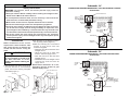
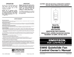
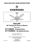
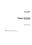
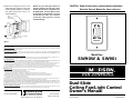
4. Attach the fan/light control to the
outlet (wall) box using two 6-32 x 3/4”
screws supplied (Figure 3). Install the
wall plate using two 6-32 x 1/4”
screws supplied.
OUTLET BOX
SW46
QUIETSLIDE
SPEED CONTROL
NOTE: For your fan/light control to
operate properly, the fan pull chain
switch must be set to operate the fan
at HIGH speed, and the light kit must
be switched to ON position. To avoid
accidental pull chain use, shorten
chains by cutting them 1” below
switch bushings.
CAUTION: Read all instructions carefully before installation.
Save this Owner's Manual for future reference.
4
3
2
4
1
EM
ER
SO
N
3
2
1
6-32 x 3/4" SCREW (2)
WALL PLATE
6-32 x 1/4" SCREW (2)
EMERSON
Figure 3
LIMITED WARRANTY
What The Warranty Covers:
All products covered by this Owner’s Manual are warranted against all defects in workmanship and materials. You must be the original
purchaser or user of the product to be covered.
What The Period Of Coverage Is:
All components are covered by this warranty for one year from the date you purchased your wall control. ANY IMPLIED WARRANTY OF
MERCHANTABILITY OR FITNESS FOR A PARTICULAR PURPOSE, MADE WITH RESPECT TO COMPONENTS AND ACCESSORIES IS ALSO
LIMITED TO ONE YEAR.
What Will Emerson Company Do To Correct Problems:
Emerson Company will replace a defective Emerson Fan/Light Control at no charge to you. We will ship the repaired product or replacement to you
at no charge, but you are responsible for all costs or removal, reinstallation and shipping of the product to Emerson.
How Can You Get Service:
YOU MUST HAVE PROOF OF YOUR PURCHASE OF THE WALL CONTROL TO OBTAIN LIMITED WARRANTY SERVICE. KEEP YOUR RECEIPT OR
OTHER PROOF OF PURCHASE. You can return the product to our factory or to your nearest authorized service center.
• To return the product to the factory, obtain a return authorization and service identification tag by writing to Air Comfort Products, Division of
Emerson Company, 8100 W. Florissant Ave., St. Louis, MO 63136. Include all model numbers shown on the product with your request.
• To return the product to an authorized service center, call 1-800-654-3545 for the address of the nearest authorized service center.
You will be responsible for all insurance, freight or other transportation charges to our factory or authorized service center. Your Emerson
Fan/Light Control should be properly packed to avoid damage in transit since we will not be responsible for any such damage.
What Is Not Covered:
This warranty also does not cover any defects, malfunctions or failures caused by:
• Repairs by persons not authorized by Emerson Company,
• Use of parts or accessories not authorized by Emerson Company,
• Mishandling, improper installation, modifications or damage to your wall control while in your possession, or
• Unreasonable use, misuse, abuse, including failing to do reasonable and necessary maintenance, and normal wear and tear.
Additionally, this warranty and any implied warranty of merchantability or fitness for a particular purpose are voided when:
• The original purchaser or user ceases to own the product, or
• The ceiling fan is moved from its original point of installation.
This warranty is only valid within the 50 states of the United States and the District of Columbia. No other written or oral warranties apply, and
no employee, agent, dealer or other person is authorized to give any warranties on behalf of Emerson Company.
REPAIR, REPLACEMENT OR A REFUND ARE THE EXCLUSIVE REMEDIES AVAILABLE UNDER THIS WARRANTY AND EMERSON IS NOT
RESPONSIBLE FOR DAMAGES OF ANY KIND, INCLUDING INCIDENTAL AND CONSEQUENTIAL DAMAGES. Incidental damages include but are
not limited to such damages as loss of time and loss of use. Consequential damages include but are not limited to the cost of repairing or
replacing other property which was damaged if this product does not work properly.
How State Law Relates To The Warranty:
Some states do not allow the exclusion or limitation of incidental or consequential damages so the above exclusion or limitation may not apply
to you. This warranty gives you specific legal rights, and you may also have other rights which vary from state to state.
EMERSON
Part No. F40BP72320000
Air Comfort Products
DIVISION OF EMERSON COMPANY
8100 W. Florissant, St. Louis, MO 63136
Form No. BP7232
Printed in Taiwan 7/99
Model Nos.
SW90W & SW90I
®
Dual-Slide
Ceiling Fan/Light Control
Owner's Manual
Form No. BP7232
Printed in Taiwan
!
WARNING
Schematic “A”
Safety Instructions
WARNING: To avoid fire, shock, and serious personal injury, follow all
instructions carefully.
1. Read your Owner's Manual carefully before installing the fan/light control.
Retain Owner's Manual for future reference.
2. To avoid possible electrical shock, be sure electricity is turned off at the
main fuse box or circuit breaker panel before wiring.
3. Make certain no bare wires are exposed outside the wire connectors.
4. Do not mount the fan/light control near heat producing equipment.
5. All wiring must conform to National and Local Electrical Codes. If you feel
you do not have enough electrical wiring knowledge or experience, have
your fan/light control installed by a licensed electrician. Any electrical work
not described in this manual should be performed by a licensed electrician.
6. Use of this control with some ceiling fans could result in fire, shock and
serious personal injury. Use this fan/light control only with capacitor speed
controlled ceiling fans.
2. Set all knobs on the fan/light control in
the off (down) position (Figure 2).
3. Make the following wire connections
(Figure 2) and secure with wire
connectors supplied:
• Black wire from fan to black wire from
fan/light control.
• White wire from fan to white wire
from the 120V AC supply source.
• Blue wire from fan to blue wire from
fan/light control.
• Black/white wire from fan/light control
to black wire from the 120V AC
supply source.
NOTE: Refer to Schematic “A” or “B”,
depending upon the location of your
120V AC supply source.
Installation
NOTE: Installation of this control
requires that a three-conductor cable
with ground wire be run between the
control wall box and the ceiling fan
outlet.
!
WARNING
To avoid possible electrical shock,
be sure electricity is turned off at
the main fuse box or circuit
breaker panel before installing the
fan/light.
1. After electricity has been turned off at
the main fuse box or circuit breaker
panel, remove the existing wall plate
and switch (Figure 1).
BLUE LIGHT SWITCH LEAD
TO HOT
BLACK/WHITE
OUTLET BOX
CONNECTIONS REQUIRED WHEN SUPPLY VOLTAGE IS FED INTO CEILING
OUTLET BOX.
CEILING OUTLET BOX
BLACK
120V AC WHITE
SUPPLY
SOURCE GROUND
BLACK
DASH LINES ARE 3
BLUE
CONDUCTOR CABLE
W/GROUND WIRE
BETWEEN CEILING
AND WALL OUTLET
BOXES
GREEN
WHITE
WALL OUTLET
BOX GROUND
BLUE
BLACK/WHITE
BLACK
FAN/LIGHT
CONTROL
Schematic “B”
CONNECTIONS REQUIRED WHEN SUPPLY VOLTAGE IS FED INTO WALL
OUTLET BOX.
GREEN
CEILING
OUTLET
BOX
WHITE
BLACK DASH LINES ARE 3
BLUE CONDUCTOR CABLE
W/GROUND WIRE
BETWEEN CEILING
AND WALL OUTLET
BOXES
SWITCH
BLUE
BLACK
GROUND
WHITE 120V AC
BLACK SUPPLY
SOURCE
4
3
2
FAN/LIGHT
CONTROL
1
EM
ER
SO
N
LIGHT
SWITCH
WALL PLATE
Figure 1
Figure 2
2
BLACK/WHITE
BACK VIEW
SPEED
SWITCH
BLACK SPEED CONTROL LEAD
3