1
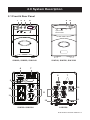
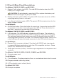
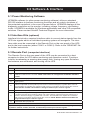
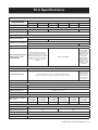
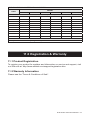
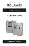
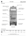
Uninterruptible Power Systems
S1K Series
Instruction Manual
Contents
1.0
Important Safety Instructions....................................................................................................... 4
1.1 Safety Precautions...............................................................................................................................................4
1.2 Conditions of Use.................................................................................................................................................5
2.0
System Description........................................................................................................................ 6
2.1 Front & Rear Panels.............................................................................................................................................6
2.2 Front & Rear Panel Descriptions..........................................................................................................................7
3.0
Preinstallation................................................................................................................................. 8
3.1 Inspection.............................................................................................................................................................8
3.2 What’s Included....................................................................................................................................................8
3.3 Optional Accessories............................................................................................................................................8
4.0
Installation...................................................................................................................................... 8
4.1 Placement.............................................................................................................................................................8
4.2 Connect to Utility Power.......................................................................................................................................8
4.3 Charge the Battery...............................................................................................................................................8
4.4 Connect the Load.................................................................................................................................................8
5.0
Operating Instructions................................................................................................................... 9
5.1 UPS Protected Output Outlets..............................................................................................................................9
5.2 Surge Protected Outlet Only.................................................................................................................................9
5.3 Switch On.............................................................................................................................................................9
5.4 Switch Off.............................................................................................................................................................9
5.5 Self-test................................................................................................................................................................9
5.6 Green Mode..........................................................................................................................................................9
6.0
Alarms........................................................................................................................................... 10
6.1 Backup................................................................................................................................................................10
6.2 Low Battery.........................................................................................................................................................10
6.3 Overload.............................................................................................................................................................10
7.0
Troubleshooting........................................................................................................................... 11
8.0
Storage.......................................................................................................................................... 11
8.1 Storage Conditions............................................................................................................................................. 11
8.2 Extended Storage............................................................................................................................................... 11
9.0
Software & Interface..................................................................................................................... 12
9.1 Power Monitoring Software................................................................................................................................12
9.2 Interface Kits.......................................................................................................................................................12
9.3 Remote Port.......................................................................................................................................................12
10.0 Specifications............................................................................................................................... 13
11.0 Registration & Warranty.............................................................................................................. 14
11.1 Product Registration.........................................................................................................................................14
11.2 Warranty Information........................................................................................................................................14
While every precaution has been taken to ensure accuracy and completeness in this manual, EGS Electrical Group, LLC. assumes no responsibility,
and disclaims all liability for damages resulting from use of this information or for any errors or omissions. The SolaHD and Emerson logos are registered in the U.S. Patent and Trademark Office. All other product or service names are the property of their registered owners. ©2011 EGS Electrical
Group, LLC. All rights reserved. Specifications are subject to change without notice.
1.0 IMPORTANT SAFETY INSTRUCTIONS
SAVE THESE INSTRUCTIONS
Congratulations on your choice of the SolaHD S1K Series Uninterruptible Power
System (UPS).
This manual contains important safety instructions that should be followed
during the installation and maintenance of the UPS. Please read this manual
thoroughly, including all safety, installation, and operating instructions before
attempting to install or operate this UPS. Please adhere to all warnings on the
unit and in this manual and follow all operating and user instructions.
This equipment is designed for industrial or commercial use and can be installed
and operated by individuals without previous training.
This equipment has been tested and found to comply with the limits for a Class
A digital device, pursuant to part 15 of the FCC Rules. These limits are designed
to provide reasonable protection against harmful interference in an industrial
installation.
1.1 Safety Precautions
!
WARNING
• To prevent the risk of fire or electric shock, install the UPS in a temperature
and humidity controlled room, free of conductive contaminants.
• Operate the UPS only from a properly grounded (earthed) ac supply.
• To reduce the risk of electric shock, do not remove the cover, as it has no
user-serviceable parts inside (including the battery). For service, contact a
qualified technician.
NOTE: Some components are live, even when ac power is disconnected.
• To reduce the risk of fire, use the proper rating when replacing the fuse.
!
CAUTION
Although your UPS has been designed and manufactured to ensure personal
safety, improper use can result in electrical shock or fire. To ensure safety, please
observe the following rules:
• Turn off the UPS and disconnect the ac supply before cleaning. Do not use
liquid or aerosol cleaners; a dry cloth is recommended to remove dust from
the surface of your UPS.
• Do not install or operate your UPS in or near water.
• Do not place the UPS on an unstable cart, stand, or table.
S1K Series Instruction Manual • 4
• Do not place the UPS under direct sunlight or close to heat emitting
sources.
• To allow proper ventilation of the UPS, do not block or cover the top and/or
bottom sides of the unit.
• Do not place the UPS power cord in any area where it may get damaged
by heavy objects.
• Follow all warnings and instructions marked on the UPS. Do not attempt to
service the UPS, as it has no user-serviceable parts inside
• Do not dispose of batteries in a fire; they may explode.
• Do not open or damage the battery. Released electrolyte is harmful to the
skin and eyes and may be toxic.
• The battery can present a risk of electrical shock and high short-circuit
current.
• To reduce the risk of fire, connect only to a circuit provided with 20 A
maximum branch circuit overcurrent protection in accordance with the
National Electrical Code, ANSI/NFPA 70.
!
ATTention
Turn off and unplug your UPS from the outlet and contact SolaHD Technical
Support at (800) 377-4384 if
• the power cord or plug is damaged;
• liquid has been spilled on the UPS;
• the fuse blows frequently;
• the UPS does not operate even when the user follows the operating
instructions.
1.2 Conditions of Use
• The input receptacle must be within 6 feet (1.8 meters) of the UPS.
• Your UPS provides conditioned power to connected equipment. Maximum
load must not exceed that shown on the UPS rating label. If uncertain,
consult your distributor or SolaHD Technical Support at (800) 377-4384.
• Placing magnetic storage media on top of the UPS may result in data
corruption.
S1K Series Instruction Manual • 5
2.0 System Description
2.1 Front & Rear Panel
1
2
3
5
4
*
4
*
*Symbols not on
S1K320 & S1K520
S1K650, S1K850, S1K1200
6
S1K320, S1K520, S1K1500
7
6
8
7
9
11
10
11
11
9
12
S1K320–S1K1200
S1K1500
S1K Series Instruction Manual • 6
2.2 Front & Rear Panel Descriptions
For Models S1K650, S1K850, and S1K1200:
1. Battery Fault indicator (red LED): The red LED illuminates when the UPS
battery is no longer useful.
!
CAUTION: Do not attempt to open the UPS or replace the battery; call
SolaHD Technical Support at (800) 377-4384.
2. Backup indicator (yellow LED): The yellow LED illuminates when the UPS is
supplying battery power to the loads.
3. Line Normal indicator (green LED): The green LED illuminates when the line
input voltage is normal.
For All Models:
4. On/Off/Test button: Press the button for more than 1 second to turn the UPS
on; press for more than 2 seconds to turn the UPS off. Press the button for
less than 1 second to activate the UPS self-testing.
For Models S1K320, S1K520, and S1K1500:
5. LED indicator: The LED indicator indicates the UPS status. The indicator is
illuminated continuously when the UPS is supplying utility power to the loads.
The indicator flashes slowly (about once every 2 seconds) when the UPS is
supplying battery power to the loads. The indicator flashes rapidly (about once
every half second) when the loads connected to the UPS exceed capacity.
For All Models:
6. Remote Port (computer interface): Provides both RS-232 and relay signals
to support Windows applications and other OS compatible solutions. Please
refer to “9.3 Remote Port” for details.
7. Tel/Surge Protection (In/Out): Provides surge suppression for telephones and
modems.
For Models S1K320, S1K520, S1K650, S1K850, and S1K1200:
8. Ac input power cord
For All Models:
9. Circuit Breaker: Provides protection from ac overload and short-circuit current.
10.Surge protected outlet only (white)
11. UPS protected output outlets (black)
For Model S1K1500:
12.Ac input receptacle
S1K Series Instruction Manual • 7
3.0 Preinstallation
3.1 Inspection
Inspect the UPS upon receipt. Damage that may have occurred in transit is not
covered under the warranty. If shipping damage is present, please contact your
local carrier and SolaHD distributor immediately.
NOTE: The packaging material is recyclable. Please reuse or dispose of it in a
responsible manner.
3.2 What’s Included
• CD with UPSMON monitoring software
• Instruction Manual
• (1) DB-9 RS-232 cable
• (1) RJ-45 cable
3.3 Optional Accessories
• S1K-PMBRK Wall/panel mount bracket kit (Not applicable for Models
S1K650 and S1K1500)
4.0 Installation
4.1 Placement
Install the UPS in a protected area with adequate airflow and free of excessive
dust. Do not operate the UPS outdoors.
4.2 Connect to Utility Power
To power up the UPS, connect the ac input connector to utility power.
4.3 Charge the Battery
The UPS charges its battery whenever it is connected to utility power. For best
results, charge the battery for 4 hours before initial use.
4.4 Connect the Loads
Connect the loads to the UPS protected output outlets on the rear of the UPS.
S1K Series Instruction Manual • 8
5.0 Operating Instructions
5.1 UPS Protected Output Outlets
The output outlets will provide protection from surges and power failures. Plug
your computer, monitor, and other “data critical” devices into these outlets.
5.2 Surge Protected Outlet Only
The surge protected outlet can offer protection against surges and transients
typically caused by lightning or disruptive loads in the building. In the event of
utility power failure, this outlet will not provide backup power to the load. Utilize
this outlet with less critical devices such as printers, scanners, fax machines, or
external speakers.
5.3 Switch On
With the UPS plugged in, press and hold the On/Off/Test button for more than 1
second until the Line Normal LED is lit. The UPS will perform self-testing each
time it is switched on.
5.4 Switch Off
Press and hold the On/Off/Test button for more than 2 seconds until the Line
Normal or Backup LED turns off.
5.5 Self-test
Use the self-test function to verify both the operation of the UPS and the condition of the battery. In normal utility power, press the On/Off/Test button for less
than 1 second to perform a self-test function. During the self-test, the UPS runs in
Backup Mode. If the UPS passes the self-test, it returns to Line Normal operation.
5.6 Green Mode
If a load of <20 watts is connected to the UPS and the ac power fails or is disconnected, the UPS will enter the Green Mode. At this time, the green LED on the
front panel will flash every 3 to 5 seconds. After approximately 3 minutes, the UPS
will shut down, preventing a deep discharge of the battery. The UPS will return to
Line Normal operation when ac power returns.
If the UPS is in the Battery Backup Mode and the load is decreased to <20 watts,
the UPS will again enter the Green Mode and will shut down within 3 minutes.
Application of ac power will return the UPS to Line Normal operation.
If the Green Mode of operation is not desired, it can be disabled by holding
down the On/Off/Test button until two beeps are heard. The Green Mode will be
disabled and will remain in this mode until the UPS is turned off.
S1K Series Instruction Manual • 9
6.0 Alarms
6.1 Backup (slow beeping)
For Models S1K650, S1K850, and S1K1200:
When in Backup Mode, the yellow LED illuminates and the UPS sounds an
audible alarm. The alarm stops when the UPS returns to Line Normal operation.
For Models S1K320, S1K520, and S1K1500:
When in Backup Mode, the green LED flashes slowly and the UPS sounds an
audible alarm. The alarm stops when the UPS returns to Line Normal operation.
6.2 Low Battery (rapid beeping)
For All Models:
In Backup Mode when the battery energy runs low, the UPS beeps rapidly until
the UPS shuts down from battery exhaustion or returns to Line Normal operation.
6.3 Overload (continuous alarm)
For Models S1K650, S1K850, and S1K1200:
When the UPS is overloaded, it sounds a continuous alarm. Remove non-critical
loads from the UPS protected output outlets to eliminate the overload.
For Models S1K320, S1K520, and S1K1500:
When the UPS is overloaded, it sounds a continuous alarm and the green LED
flashes rapidly. Remove non-critical loads from the UPS protected output outlets
to eliminate the overload.
S1K Series Instruction Manual • 10
7.0 Troubleshooting
Table 1: Troubleshooting
Problem
UPS is not on; green LED will not
illuminate
UPS is always in Backup Mode
Backup time is too short
Cause
Solution
UPS is off or On/Off/Test button was
not pushed long enough
Press the On/Off/Test button for more
than 2 seconds
Battery voltage is less than 10 V
(20 V for S1K1500)
Recharge the UPS for at least 4
hours. If it still does not start, check
the input fuse.
Other failure
Call SolaHD Technical Support
Load less than 20 W in Backup Mode
Normal condition
Power cord is loose
Plug in the power cord
Input ac power is not available
Check fuses/breakers
Other failure, PCB, etc.
Call SolaHD Technical Support
Line voltage too high, too low, or
blackout
Normal condition
Battery is not fully charged
Recharge the UPS for at least 4
hours
Other failure
Call SolaHD Technical Support
Continuous beep
Overload condition
Remove the non-critical loads
Red LED is illuminated
Battery failure
Call SolaHD Technical Support
Technical Support
For further assistance, please contact SolaHD Technical Support at (800) 377-4384/(847) 268-6651 or by e-mail
at [email protected].
8.0 Storage
8.1 Storage Conditions
NOTE: Before storing, charge the UPS for at least 4 hours.
Store the UPS covered and upright in a cool, dry location with its battery fully
charged. Remove any accessories from the accessory slot and disconnect any
cables connected to the Remote Port to avoid unnecessary draining of the battery.
8.2 Extended Storage
During extended storage in environments where the ambient temperature is
-15°C to +30°C (+5°F to +86°F), charge the UPS battery every 6 months.
During extended storage in environments where the ambient temperature is
+30°C to +45°C (+86°F to +113°F), charge the UPS battery every 3 months.
S1K Series Instruction Manual • 11
9.0 Software & Interface
9.1 Power Monitoring Software
UPSMON software (or other power monitoring software) utilizes a standard
RS-232 interface to perform monitoring functions and an orderly shutdown of
the protected equipment in the event of power failure. UPSMON displays all the
diagnostic symptoms on the monitor, including voltage, frequency, and battery
levels. UPSMON is available for Windows applications and other OS compatible
solutions. Please contact SolaHD Technical Support for more information.
9.2 Interface Kits (optional)
Interface kits include a required interface cable to convert status signals from the
UPS into signals which an individual operating system will recognize. The interface cable must be connected to the Remote Port on the rear panel of the UPS
and to the host computer (either COM 1 or COM 2). Refer to the “READ.ME” file
for further instructions.
9.3 Remote Port (computer interface)
The Remote Port on the rear panel of the UPS may be connected to a host
computer to allow for UPS status monitoring and operation control. Functions
include: broadcasting a warning when power fails, closing any open file before
the batteries are exhausted, and turning off the UPS.
Table 2: Remote Port PIN Configurations
PIN
Signals Description
2
Transmitted data (TD) RS-232
3
Received data (RD) RS-232 remote shutdown. The UPS will shut down when a high RS-232 level is
sustained on PIN 3 for 0.5 seconds. NOTE: This feature is not applicable for Models S1K320 &
S1K520.
4
Data terminal ready (DTR) +12 V
5
Signal ground
6
Ac failure. PIN 6 generates a high to low signal when there is an input line failure. PIN 6 is an open
collector output that must be pulled up to a common referenced supply no greater than +40 V dc.
The transistors are capable of a maximum load of 25 mA; only PIN 5 can be used as the common.
NOTE: Models S1K320 and S1K520 are designed without open collector signals.
7
Request to send (RTS) -12 V
8
Battery low. PIN 8 generates a high to low signal when the internal battery of the UPS has less than
5 minutes of backup time remaining. PIN 8 is an open collector output that must be pulled up to a
common referenced supply no greater than +40 V dc. The transistors are capable of a maximum
load of 25 mA; only PIN 5 can be used as the common. NOTE: Models S1K320 and S1K520 are
designed without open collector signals.
9
Transmitted data (TD) RS-232
Notes
(1) Switch rating is +40 V dc, 25 mA non-inductive. (2) PIN 5 should be connected to signal ground only.
(3) Models S1K650, S1K850, S1K1200, and S1K1500 provide open collector signals.
S1K Series Instruction Manual • 12
10.0 Specifications
Table 3: Technical Specifications
Model
Parameters
Capacity, VA/W
S1K320
S1K520
S1K650
S1K850
S1K1200
S1K1500
320/240
520/360
650/390
850/600
1200/720
1500/900
input
Voltage (Single phase)
115 V ± 25%
115 V ± 20%
Frequency
115 V ± 25%
50 or 60 Hz ± 10% (auto sensing)
Output
Step sine wave at 115 V
Voltage (on battery)
± 10%
± 5%
50 or 60 Hz
Frequency (on battery)
± 0.3 Hz
Transfer Time
Auto Voltage Regulation
(AVR function under
Normal Mode)
± 1 Hz
4 ms typical
AVR automatically increases
output voltage 15% above input
voltage if 91% to 75% of nominal
is detected. AVR decreases output
voltage 13% below input voltage
if +9% to +25% of nominal is
detected.
AVR automatically increases
output voltage
15% above input
voltage if 91% to
75% of nominal
is detected.
AVR decreases
output voltage
13% below input
voltage if +9% to
+25% of nominal
is detected.
AVR not available
protection
Unit Input
Overload Protection
Fuse or circuit breaker for overload & short circuit protection
UPS automatically shuts
down if overload
exceeds 110%
of nominal at 60
seconds, 130%
at 3 seconds.
UPS automatically shuts down if overload exceeds 105% of
nominal at 20 seconds, 120% at 10 seconds, 130% at 3 seconds.
Short Circuit
UPS output cuts off immediately or input fuse protection
environment
Operating Temperature
0°C to +40°C
Humidity
0 to 95% non-condensing
Maximum Elevation
10,000 ft. (3,000 m)
Audible Noise
<40 dBA (1 m from surface)
physical
Dimensions, in. (mm)
WxDxH
Net Weight, lb. (kg)
3.8 (97) x
12.6 (320) x
5.3 (135)
3.8 (97) x
12.6 (320) x
5.3 (135)
3.8 (97) x
10.4 (265) x
5.3 (135)
3.8 (97) x
12.6 (320) x
5.3 (135)
3.8 (97) x
12.6 (320) x
5.3 (135)
5.11 (130) x
15.0 (382) x
7.5 (192)
12.4 (5.6)
14.3 (6.5)
8.1 (3.7)
10.8 (4.9)
10.8 (4.9)
30.0 (13.6)
battery
Type
Typical Recharge Time
Backup Time
Sealed, maintenance-free, lead acid batteries
4 hr.
6 hr.
See Table 4 on page 14
agency approvals
Safety
UL 1778, cULus Listed, FCC Part 15, Subpart B, Class A
S1K Series Instruction Manual • 13
Table 4: Typical Battery Backup Times
Load
Model
S1K320
S1K520
S1K650
S1K850
S1K1200
S1K1500
Backup Times (hr:min:s)
10%
02:18:00
01:35:00
01:36:00
00:54:00
00:45:00
01:16:15
20%
01:03:30
00:42:00
00:58:00
00:30:00
00:27:00
00:28:00
30%
00:35:45
00:21:00
00:36:00
00:21:00
00:19:00
00:12:30
40%
00:22:30
00:12:30
00:20:00
00:17:00
00:14:00
00:07:30
50%
00:15:00
00:08:00
00:14:00
00:11:00
00:08:00
00:04:30
60%
00:11:45
00:06:00
00:10:00
00:08:00
00:05:00
00:04:30
70%
00:08:15
00:04:30
00:08:00
00:05:30
00:04:30
00:02:15
80%
00:06:00
00:03:30
00:06:00
00:05:00
00:03:30
00:01:45
90%
00:04:45
00:02:15
00:04:00
00:04:00
00:02:00
00:01:30
100%
00:04:00
00:01:45
00:03:00
00:03:00
00:01:30
00:01:00
notes
Backup times are based on a fully charged battery
11.0 Registration & Warranty
11.1 Product Registration
To register your product for updates and information on service and support, visit
our Web site at: http://www.solahd.com/support/registration.htm.
11.2 Warranty Information
Please see the “Terms & Conditions of Sale”.
S1K Series Instruction Manual • 14
www.solahd.com
(800) 377-4384 • (847) 268-6651
[email protected]
Part Number: A272-067 Rev 14
January 2011