1
NetSure™ LMS Data Processing Unit
Installation Instructions, Section 5879 (Issue BA, April 7, 2014)
Specification Number: 586505000 and 586505500
Model Number: LMS1000
Firmware Version 12.0
Also for the LMS Monitoring System factory integrated into Spec. Nos.
582140000, 582140001, and 582126100 NetSure™ Power Systems (NPS).
NetSure™ LMS Data Processing Unit
Installation Instructions, Section 5879 (Issue BA, April 7, 2014)
This page is intentionally blank.
Spec. No: 58650500, 586505500
Model No: LMS1000
Code: Section 5879
Issue BA, April 7, 2014
NetSure™ LMS Data Processing Unit
Installation Instructions, Section 5879 (Issue BA, April 7, 2014)
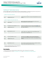
Table of Contents
Admonishments Used in this Document ............................................................................................................... iv
Static Warning ...................................................................................................................................................... v
FCC Information ................................................................................................................................................... vi
General Information and Installation Checklist ...................................................................................................... 1
Preface ....................................................................................................................................................................... 1
Installation Acceptance Checklist ............................................................................................................................... 1
Installing LMS1000 ................................................................................................................................................ 2
Installing the LMS1000 Display Option ....................................................................................................................... 2
Mounting the 586505000/586505500 Main Cabinet and Expansion Cabinet(s) (if furnished) .................................... 2
Mounting............................................................................................................................................................ 2
Grounding Connection ....................................................................................................................................... 2
Mounting the Optional Expansion Assembly(s) (if furnished) ..................................................................................... 2
Mounting............................................................................................................................................................ 2
Grounding Connection ....................................................................................................................................... 2
Installing Circuit Cards ............................................................................................................................................... 2
Circuit Card Handling.......................................................................................................................................... 3
Identifying the Circuit Cards ............................................................................................................................... 3
Installing an Optional Modem Circuit Card.......................................................................................................... 3
Installing the CPU Circuit Card(s) ........................................................................................................................ 7
Installing Input/Output (I/O) Circuit Cards .......................................................................................................... 9
Making Electrical Connections ................................................................................................................................. 16
Observe the Following Admonishment ............................................................................................................. 16
Wiring Considerations ...................................................................................................................................... 16
586505000/586505500 Main and Expansion Cabinet Grounding Connection
(586505000/586505500 only) ......................................................................................................................... 16
586505000/586505500 Main and Expansion Cabinet DC Input Power Connection
(586505000/586505500 only) ......................................................................................................................... 16
External CPU/Hardware Fail Alarm Connections ................................................................................................ 26
Local Terminal Port Connections ...................................................................................................................... 26
Gateway Port Connections (if Gateway Software Option is installed) ................................................................ 27
Internal Modem Port Connections .................................................................................................................... 27
Ethernet Port Connections (10M) ..................................................................................................................... 27
OEM1 Port Connections (if required) (586505000/586505500 Only) ............................................................... 28
OEM2 Port Connections (if required) (586505000/586505500 Only) ............................................................... 28
OEM3 Port Connections (if required) (586505000/586505500 Only) ............................................................... 29
582140000/582140001/582126100 Power System's LMS RS-485 Port Connections (RS-485 Port).................. 31
LMS1000 Input/Output (I/O) Circuit Card Connections ..................................................................................... 31
Interconnecting the Optional 586505000/586505500 Expansion Assembly(s) (if furnished) to
Customer Equipment ....................................................................................................................................... 41
Interconnecting the Expansion Cabinet(s) and Assembly(s) (if furnished) into the LMS1000 Network
(586505000/586505500 Only)......................................................................................................................... 45
Spec. No: 58650500, 586505500
Model No: LMS1000
[i]
Code: Section 5879
Issue BA, April 7, 2014
NetSure™ LMS Data Processing Unit
Installation Instructions, Section 5879 (Issue BA, April 7, 2014)
Energy Management Connections (when used w/ 'traditional' rectifiers external to the system) ....................... 47
Sequential Start Connections ............................................................................................................................ 48
LMS Dual MCA Interface Software Option ................................................................................................................. 49
Powering Up and Checking System Operation .......................................................................................................... 49
Initial Startup Preparation ................................................................................................................................. 49
Powering Up the System ................................................................................................................................... 49
Logging Onto the System .................................................................................................................................. 49
586505000/586505500 Main Cabinet or 582140000/582140001/582126100 Primary Power Bay
I/O Circuit Card Verification ............................................................................................................................... 49
Software Option Verification ............................................................................................................................. 50
Verifying Programmable Status LED Indicator Operation .................................................................................. 50
Verifying Relay Operation.................................................................................................................................. 50
Logging Off of the System ................................................................................................................................. 51
Configuring the System ..................................................................................................................................... 51
Installation Logs/Worksheets ................................................................................................................................... 51
Configuring LMS1000 .......................................................................................................................................... 69
Getting Started ......................................................................................................................................................... 69
Required Password ............................................................................................................................................ 69
What Can Be Changed ....................................................................................................................................... 69
Descriptions of Configuration Attributes .................................................................................................................. 70
Unit Identification ............................................................................................................................................. 70
GET Community String ...................................................................................................................................... 70
TRAPS Community String .................................................................................................................................. 70
SET Community String ...................................................................................................................................... 70
TRAP Addresses ................................................................................................................................................. 70
Gateway Address............................................................................................................................................... 70
Netmask Address .............................................................................................................................................. 71
Host Addresses ................................................................................................................................................. 71
Alarm Classes .................................................................................................................................................... 71
Program Lines ................................................................................................................................................... 71
Examples of Various Types of Program Lines ..................................................................................................... 74
Program Line Time Periods ................................................................................................................................ 75
Common Channel Attributes............................................................................................................................. 75
Analog Channel Attributes ................................................................................................................................ 75
Binary Channel Attributes.................................................................................................................................. 77
Function Channel Attributes.............................................................................................................................. 78
LED Channel Attributes ..................................................................................................................................... 78
Relay Channel Attributes ................................................................................................................................... 79
User Attributes .................................................................................................................................................. 80
Groups .............................................................................................................................................................. 82
System Alarm Reporting ................................................................................................................................... 82
Initial Configuration .................................................................................................................................................. 83
Spec. No: 58650500, 586505500
Model No: LMS1000
[ii]
Code: Section 5879
Issue BA, April 7, 2014
NetSure™ LMS Data Processing Unit
Installation Instructions, Section 5879 (Issue BA, April 7, 2014)
Setting Local Port Communications Parameters ............................................................................................... 83
Setting Gateway Port Parameters (if Gateway Software Option Installed) ......................................................... 83
Setting System Configuration ........................................................................................................................... 83
Setting Email Parameters ................................................................................................................................ 105
Configuring Groups ........................................................................................................................................ 105
Setting User Timeout ...................................................................................................................................... 105
Setting WEB Interface ..................................................................................................................................... 105
Setting the Battery Discharge Timer Feature (if required) ............................................................................... 105
Setting SNMP.................................................................................................................................................. 105
Setting Energy Management (if Energy Management Software Option Installed) ........................................... 106
Setting Sequential Start (if Sequential Start Software Option Installed) .......................................................... 107
Setting TL1 (if TL1 Software Option Installed) ................................................................................................. 110
Configuration Required to Allow Access Door to be Locked and Unlocked Manually via LMS1000 (if
586505000/586505500 List 80 installed) ....................................................................................................... 112
Configuring Battery Thermal Runaway Feature ............................................................................................... 112
Configuring MCA "CAN I/0" Circuit Cards (if installed in a Spec. No. 582140000, 5821400001, or
582126100 Bay) ............................................................................................................................................. 113
Configuring Analog Channels for Use with the 130VDC Monitoring Wire Harness .......................................... 113
LMS Dual MCA Interface Software Option ....................................................................................................... 113
Checking the System Time ............................................................................................................................. 113
Checking for Alarms........................................................................................................................................ 114
Downloading the Configuration ..................................................................................................................... 114
Subsequent Configuration ..................................................................................................................................... 114
Changing the Date, Time, Unit Name, Unit Number, System Identifier, Unit Header, Unit Pager
Code, and Pager Delay .................................................................................................................................... 114
Adding and Configuring LMS1000 Expansion Nodes ....................................................................................... 115
Changing the Analog Channel Configurations ................................................................................................ 117
Changing the Binary Channel Configurations .................................................................................................. 123
Changing the Energy Management Channel Configurations ........................................................................... 126
Changing the Function Channel Configurations .............................................................................................. 128
Changing the LED Channel Configurations...................................................................................................... 133
Changing the Relay Channel Configurations ................................................................................................... 136
Changing the Number of Rings before Answer ............................................................................................... 139
Changing the User Configurations .................................................................................................................. 139
Adding or Deleting Channels from the User Configurations ............................................................................ 144
Setting Alarm Class Names ............................................................................................................................. 145
Changing System Alarm Reporting or Individual User Reports ........................................................................ 146
Configuring Channels Into Groups .................................................................................................................. 147
Resetting Defaults .......................................................................................................................................... 148
NetPerform™ Optimization Services ................................................................................................................. 149
Spec. No: 58650500, 586505500
Model No: LMS1000
[iii]
Code: Section 5879
Issue BA, April 7, 2014
NetSure™ LMS Data Processing Unit
Installation Instructions, Section 5879 (Issue BA, April 7, 2014)
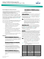
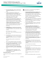
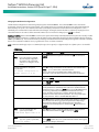
Admonishments Used in this Document
DANGER! Warns of a hazard the reader will be exposed to that will likely result in death or serious injury
if not avoided. (ANSI, OSHA)
Danger
Warning
Caution
WARNING! Warns of a potential hazard the reader may be exposed to that could result in death or
serious injury if not avoided. This admonition is not used for situations that pose a risk only to
equipment, software, data, or service. (ANSI)
CAUTION! Warns of a potential hazard the reader may be exposed to that could result in minor or
moderate injury if not avoided. (ANSI, OSHA) This admonition is not used for situations that pose a risk
only to equipment, data, or service, even if such use appears to be permitted in some of the applicable
standards. (OSHA)
ALERT! Alerts the reader to an action that must be avoided in order to protect equipment, software,
data, or service. (ISO)
Alert
ALERT! Alerts the reader to an action that must be performed in order to prevent equipment damage,
software corruption, data loss, or service interruption. (ISO)
Alert
FIRE SAFETY! Informs the reader of fire safety information, reminders, precautions, or policies, or of the
locations of fire-fighting and fire-safety equipment. (ISO)
Fire Safety
SAFETY! Informs the reader of general safety information, reminders, precautions, or policies not related
to a particular source of hazard or to fire safety. (ISO, ANSI, OSHA)
Safety
Spec. No: 58650500, 586505500
Model No: LMS1000
[iv]
Code: Section 5879
Issue BA, April 7, 2014
NetSure™ LMS Data Processing Unit
Installation Instructions, Section 5879 (Issue BA, April 7, 2014)
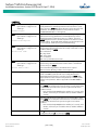
Static Warning
This equipment contains static sensitive components. The warnings listed below must be observed to prevent damage to these
components. Disregarding any of these warnings may result in personal injury or damage to the equipment.
1.
Strictly adhere to the procedures provided in this document.
2.
Before touching any equipment containing static sensitive components, discharge all static electricity from yourself by wearing
a wrist strap grounded through a one megohm resistor. Some wrist straps, such as Emerson Network Power Part Number
631810600, have a built-in one megohm resistor; no external resistor is necessary. Read and follow wrist strap manufacturer’s
instructions outlining use of a specific wrist strap.
3.
Do not touch traces or components on equipment containing static sensitive components.
Handle equipment containing static sensitive components only by the edges that do not have connector pads.
4.
After removing equipment containing static sensitive components, place the equipment only on conductive or anti-static
material such as conductive foam, conductive plastic, or aluminum foil. Do not use ordinary Styrofoam™ or ordinary plastic.
5.
Store and ship equipment containing static sensitive components only in static shielding containers.
6.
If necessary to repair equipment containing static sensitive components, wear an appropriately grounded wrist strap, work on a
conductive surface, use a grounded soldering iron, and use grounded test equipment.
Spec. No: 58650500, 586505500
Model No: LMS1000
[v]
Code: Section 5879
Issue BA, April 7, 2014
NetSure™ LMS Data Processing Unit
Installation Instructions, Section 5879 (Issue BA, April 7, 2014)
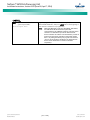
FCC Information
The MCA Interface Modem Option (if installed) has been granted a registration number by the Federal Communications Commission,
under Part 68 rules and regulations for direct connection to the telephone lines. In order to comply with these FCC rules, the following
instructions must be carefully read and applicable portions followed completely:
a.
Direct connection to the telephone lines may be made only through the standard plug- ended cord furnished to the
utility-installed jack. No connection may be made to party or coin phone lines. Prior to connecting the device to the telephone
lines, you must:
b.
Call your telephone company and inform them you have an FCC registered device you desire to connect to their telephone
lines. Give them the number(s) of the line(s) to be used, the make and model of the device, the FCC registration number and
ringer equivalence. This information will be found on the device or enclosed with instructions as well as the jack suitable for
your device.
c.
After the telephone company has been advised of the above you may connect your device if the jack is available, or after the
telephone company has made the installation.
d.
Repairs may be made only by the manufacturer or his authorized service agency. Unauthorized repairs void registration and
warranty. Contact seller or manufacturer for details of permissible user performed routine repairs, and where and how to have
other than routine repairs.
e.
If, through abnormal circumstances, harm to the telephone lines is caused, it should be unplugged until it can be determined if
your device or the telephone line is the source. If your device is the source, it should not be reconnected until necessary repairs
are effected.
f.
Should the telephone company notify you that your device is causing harm, the device should be unplugged. The telephone
company will, where practicable, notify you, that temporary discontinuance of service may be required. However, where prior
notice is not practicable, the telephone company may temporarily discontinue service, if such action is reasonably necessary, in
such cases the telephone company must (A) Promptly notify you of such temporary discontinuance, (B) Afford you the
opportunity to correct the condition and (C) Inform you of your rights to bring a complaint to the FCC under their rules.
g.
The telephone company may make changes in its communications facilities, equipment, operations or procedures, where such
action is reasonably required in the operation of its business and is not inconsistent with FCC rules. If such changes can be
reasonably expected to render any customer’s devices incompatible with telephone company facilities, or require modification
or alteration, or otherwise materially affect its performance, written notification must be given to the user, to allow
uninterrupted service.
The following information is provided here and on a label attached to the outside of the MCA Interface Modem Option (if installed).
Spec. No: 58650500, 586505500
Model No: LMS1000
JACK
RINGER EQUIVALENCE
FCC REGISTRATION NUMBER
RJ-11
0.2A
B46USA-22429-MM-E
[vi]
Code: Section 5879
Issue BA, April 7, 2014
NetSure™ LMS Data Processing Unit
Installation Instructions, Section 5879 (Issue BA, April 7, 2014)
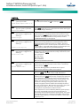
General Information and Installation
Checklist
Optional Expansion Assembly(s) Mounted in Customer
Equipment
Optional Modem Circuit Card Installed
CPU Circuit Card(s) Installed
Four Input Analog Circuit Card Installed after Making any
Jumper Adjustment as Required
Eight Input Analog Circuit Card Installed
Twelve Input Analog Circuit Card Installed
Four Input Binary Circuit Card Installed
Refer to SAG586505000/SAG586505500 (System Application
Guide) for additional information. The SAG can be accessed via the
CD (Electronic Documentation Package) furnished with your
system.
Eight Input Binary Circuit Card Installed after Making any
Jumper Adjustment as Required
Four Output (Form-C) Relay Circuit Card Installed after
Making any Jumper Adjustment as Required
Note: The LMS cabinet (Spec. No. 586505000/586505500) can be
Eight Input Temperature Circuit Card Installed and
Ground Lead Attached to Frame Ground
Main and Expansion Cabinets Grounding Connection
Made (586505000/586505500 only)
Main and Expansion Cabinets DC Input Power Connection
Made (586505000/586505500 only)
External CPU/Hardware Fail Alarm Connections Made
Local Port Connections Made
Modem Port Connections Made
Ethernet Port Connections Made
OEM1 Port Connections Made (586505000/586505500
only)
OEM2 Port Connections Made (586505000/586505500
only)
OEM3 (VPS/NPS) Port Connections Made
(586505000/586505500 only)
Gateway Port (if available) Connections Made
Connections Made to all Four Input Analog Circuit Cards
Installed
Connections Made to all Eight Input Analog Circuit Cards
Installed
Connections Made to all Twelve Input Analog Circuit
Cards Installed
Connections Made to all Four Input Binary Circuit Cards
Installed
Preface
This document (Section 5879) provides Installation Instructions for
Monitoring System Model LMS1000, Spec. Nos. 586505000 and
586505500. These instructions also provide procedures for the
integrated LMS of Spec. Nos. 582140000, 582140001, and
582126100 Power Systems.
For User Instructions, refer to Section 5847 provided on the CD
(Electronic Documentation Package) furnished with your system.
used in Vortex® Power Systems (VPS) and NetSure™ Power
Systems (NPS). The LMS is also factory integrated (w/out using
the Spec. No. 586505000/586505500 cabinet) into Spec. Nos.
582140000, 582140001, and 582126100 NetSure™ Power
Systems (NPS). In this document, reference to an LMS in a VPS
or NPS using the Spec. No. 586505000/586505500 cabinet
will be VPS/NPS (LMS commands and responses specific to this
interface use ‘NETSURE’). Reference to an LMS in a Spec. No.
582140000, 582140001, and 582126100 NPS Power System
will be NPS (LMS commands and responses specific to this
interface use ‘NPS’).
Installation Acceptance Checklist
Provided below is an Installation Acceptance Checklist. This
checklist helps ensure proper installation and initial operation of
the system. As the procedures presented in this document are
completed, check the appropriate box on this list. If the procedure
is not required to be performed for your installation site, also
check the box in this list to indicate that the procedure was read.
When installation is done, ensure that each block in this list has
been checked.
Note: The system is not powered up until the end of this checklist.
Note: Some of these procedures may have been performed at the
factory for you.
Installing LMS1000
LMS1000 Display Option Installed
(586505000/586505500 only)
Main Cabinet and Expansion Cabinet(s) Mounted in a
Relay Rack (586505000/586505500 only)
Spec. No: 58650500, 586505500
Model No: LMS1000
[1 of 149]
Code: Section 5879
Issue BA, April 7, 2014
NetSure™ LMS Data Processing Unit
Installation Instructions, Section 5879 (Issue BA, April 7, 2014)
Connections Made to all Eight Input Binary Circuit Cards
Installed
Connections Made to all Four Output (Form-C) Relay
Circuit Cards Installed
Connections Made to all Eight Input Temperature Circuit
Cards Installed
Optional Expansion Assembly(s) (if furnished)
Interconnected to Customer Equipment
All 586505000/586505500 Expansion Cabinets,
582140000/582140001/582126100 Secondary Bays,
and/or 586505000/586505500 Expansion Assemblies (if
furnished) Interconnected into LMS1000 Network
Energy Management Connections Made, if required
Sequential Start Connections Made, if required
System Powered Up and Checked
Grounding Connection
Main and Expansion Cabinets: The earth ground connection to the
cabinet is made via an external connection brought to the outside
of the cabinet. Refer to "MAKING ELECTRICAL CONNECTIONS" in
this section for details.
Relay Rack: Refer to the National Electrical Code, applicable local
codes, and your specific site requirements.
Mounting the Optional Expansion Assembly(s) (if
furnished)
System Configured
The installer should be familiar with the installation requirements
and technique to be used in mounting the assembly(s).
Installing LMS1000
Mounting
Installing the LMS1000 Display Option
Refer to Section 5942 or Section 5943 to field install an LMS1000
Display option. These are provided in the LMS1000 Installation
Manual, and on the CD provided with your system documentation.
The option is factory installed if ordered with the system.
Mounting the 586505000/586505500 Main Cabinet
and Expansion Cabinet(s) (if furnished)
The installer should be familiar with the installation requirements
and technique to be used in mounting the cabinet(s).
The assembly(s) is to be mounted in customer equipment, as
required.
The assembly(s) is provided with a back sheetmetal panel with
mounting holes. Mount the assembly to a suitable surface. Refer
to SAG586505000/SAG586505500 for mounting hole dimensions.
The SAG can be accessed via the CD (Electronic Documentation
Package) furnished with your system.
Grounding Connection
The earth ground connection to the assembly(s) is to be made
with the hardware used to mount to assembly(s). This requires the
use of a ground washer with the assembly(s) mounting hardware.
A ground washer is an internal-external tooth, dish-type lock
washer.
Note that Spec. Nos. 582140000, 582140001, and 582126100
Power Systems do not use the LMS1000 Cabinets. The LMS is
factory integrated into the Power Systems.
Mounting
The cabinet(s) is to be mounted in a relay rack with 1 or 1-3/4 inch
multiple drilling.
586505000 Lists 1 and 6: The cabinet(s) is provided with
reversible mounting angles to allow mounting in a 19 inch or 23
inch wide relay rack. The mounting angles may also be positioned
for flush front mounting, 5-inch front projection mounting, or
6-inch front projection mounting. If necessary, remove and
reposition the reversible mounting angles to meet your
requirements.
Spec. No: 58650500, 586505500
Model No: LMS1000
Note: A removable label is provided on the front panel of the Main
Cabinet. This allows the user to write the functions of the
programmable LEDs, if desired.
Configuring LMS1000
586505000 and 586505500 Lists 2 and 7: The cabinet(s) is to be
mounted in a 23 inch wide relay rack. The mounting angles may
also be positioned for flush front mounting, 5-inch front projection
mounting, or 6-inch front projection mounting. If necessary,
remove and reposition the reversible mounting angles to meet
your requirements.
Installing Circuit Cards
Circuit cards may have been factory installed for you.
The 586505000/586505500 cabinet(s) should be unpacked and
mounted prior to unpacking and installing the circuit cards. Note
that Spec. Nos. 582140000, 582140001, and 582126100 Power
Systems do not use the LMS1000 Cabinets. The LMS is factory
integrated into the Power Systems.
[2 of 149]
Code: Section 5879
Issue BA, April 7, 2014
NetSure™ LMS Data Processing Unit
Installation Instructions, Section 5879 (Issue BA, April 7, 2014)
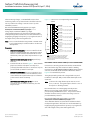
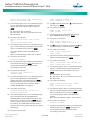
and grounded through the CPU circuit card via a metal
standoff located on the modem circuit card and a
supplied screw.
Circuit Card Handling
Warning
WARNING! Before handling any circuit card, read and
follow the instructions contained on the Static Warning
Page located at the beginning of this document.
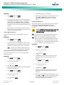
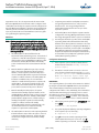
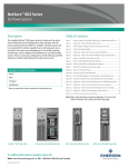
Before performing the next steps, study the diagram in
Figure 1. Locate the mating connectors on the modem
and CPU circuit cards. Locate the mounting holes for the
plastic standoffs on the modem circuit card and the
corresponding holes on the CPU circuit card.
A static wrist strap grounded through a one megohm
resistor should always be worn when handling the
circuit cards.
Identifying the Circuit Cards
Each circuit card associated with the system is shipped in a
separate package. These circuit cards can be identified through
two methods as described below.
a.
the Emerson Network Power part number printed on the
outside of the shipping carton
b.
the Emerson Network Power part number silkscreened
on the component side of the circuit card
5.
Refer to Figure 1, and snap the three supplied plastic
standoffs into the holes provided on the modem circuit
card. Ensure the standoffs protrude towards the
component side of the circuit card.
6.
Hold the modem circuit card by the edges. Orient the
circuit card as shown in Figure 1. Align the mating
connectors on the modem and CPU circuit cards, and the
standoffs on the modem circuit card with the
corresponding holes on the CPU circuit card. Push the
modem circuit card down onto the CPU circuit card,
ensuring the mating connectors are properly aligned,
until all three plastic standoffs snap into holes on the CPU
circuit card.
7.
Refer to Figure 1 and secure the grounding screw into the
proper mounting hole on the CPU circuit card (from the
bottom of the CPU circuit card). This screw secures the
CPU circuit card to the metal standoff located on the
modem circuit card.
8.
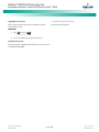
582140000/582140001/582126100 Power System Only:
Install the supplied sheetmetal bracket as shown in
Figure 1. Secure with the supplied flathead screw.
9.
Install the CPU circuit card into the cabinet or bay as
described in the next procedure.
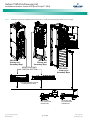
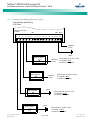
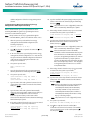
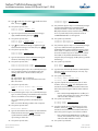
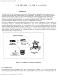
Installing an Optional Modem Circuit Card
The optional modem circuit card plugs onto the top of the
LMS1000 CPU circuit card installed in the 586505000/586505500
LMS1000 Main Cabinet or 582140000/582140001/582126100
Primary Power Bay.
PROCEDURE:
Note: Refer to Figure 1 as this procedure is performed.
1.
Connect an approved grounding strap to your wrist.
Attach the other end to a suitable ground.
2.
Unpack the Modem circuit card (P/N 508951).
3.
586505000/586505500 LMS1000 Main Cabinet: If the
CPU circuit card is not already installed in the Main
Cabinet, unpack the CPU circuit card (P/N 514024). If the
CPU circuit card is already installed, rotate the two
captive fasteners on the front of the Main Cabinet until
the arrow on the fastener points up or down, and pivot
the door open. Remove the CPU circuit card.
or
582140000/582140001/582126100 Power System: If
the CPU circuit card is not already installed in the Primary
Power Bay, unpack the CPU circuit card (P/N 521185). If
the CPU circuit card is already installed, remove the LMS
CPU circuit card from the Primary Power Bay.
4.
The modem circuit card connects to the CPU circuit card
via a connector that contains a set of pins that plug into a
mating connector on the CPU circuit card. The modem
circuit card is secured to the CPU circuit card via three
supplied plastic standoffs that snap into holes located on
the modem circuit card and corresponding holes in the
CPU circuit card. The modem circuit card is also secured
Spec. No: 58650500, 586505500
Model No: LMS1000
[3 of 149]
10. When all circuit cards have been installed, remove the
grounding wrist strap.
11. After all electrical connections are made (as described
later), close the cabinet door and secure with the two
captive fasteners (arrow on fastener points towards
outside of cabinet). In a
582140000/582140001/582126100 Power System,
close the bay's front door.
12. 586505000/586505500 LMS1000 Main Cabinet: Attach
the supplied self-adhesive FCC label to the outside rear
panel of the cabinet near the phone jack.
or
582140000/582140001/582126100 Power System:
Attach the supplied self-adhesive FCC label to the
sheetmetal located at the bottom of the LMS CPU circuit
card housing (near the phone connector on the Modem).
Code: Section 5879
Issue BA, April 7, 2014
NetSure™ LMS Data Processing Unit
Installation Instructions, Section 5879 (Issue BA, April 7, 2014)
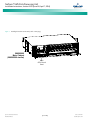
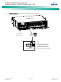
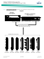
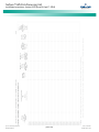
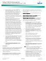
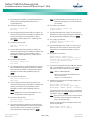
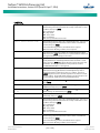
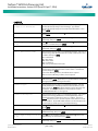
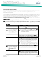
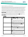
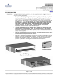
Figure 1. Installing the Modem Circuit Card (cont'd on next page)
586505000
Main Cabinet
(586505500 similar)
Main
CPU Circuit
Card
Spec. No: 58650500, 586505500
Model No: LMS1000
[4 of 149]
Code: Section 5879
Issue BA, April 7, 2014
NetSure™ LMS Data Processing Unit
Installation Instructions, Section 5879 (Issue BA, April 7, 2014)
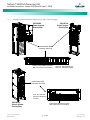
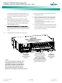
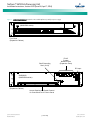
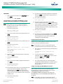
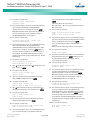
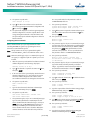
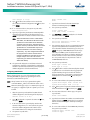
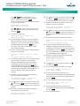
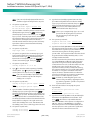
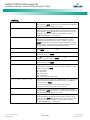
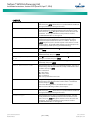
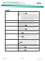
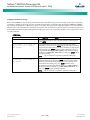
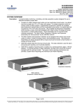
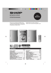
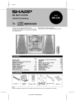
Figure 1. Installing the Modem Circuit Card (cont'd from previous page, cont'd on next page)
582140000
Power System
Primary Bay
582126100
Power System
Primary Bay
MONITORING AND
CONTROL SECTION
Optional LMS Monitoring System
Main CPU Circuit Card Location
Spec. No. 582140000 shown,
Spec. No. 582126100 similar.
MONITORING AND
CONTROL SECTION
Front door assembly
removed in illustration
for clarity.
582140001
Power System
Primary Bay
Spec. No: 58650500, 586505500
Model No: LMS1000
Optional LMS Monitoring System
Main CPU Circuit Card Location
[5 of 149]
Code: Section 5879
Issue BA, April 7, 2014
NetSure™ LMS Data Processing Unit
Installation Instructions, Section 5879 (Issue BA, April 7, 2014)
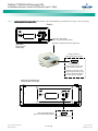
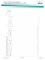
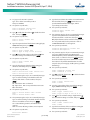
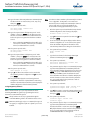
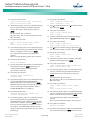
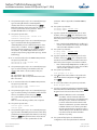
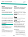
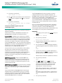
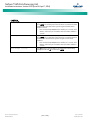
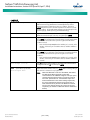
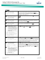
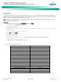
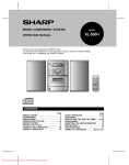
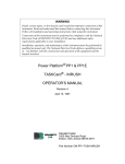
Figure 1. Installing the Modem Circuit Card (cont'd from previous page)
Screw
Sheetmetal
Bracket
582140000/582140001/
582126100 Only
582140000/582140001/
582126100 Only
Modem Circuit
Card P/N 508951
(Trace Side Up)
Plastic
Standoffs (3)
CPU Circuit Card
P/N 514024 or 521185
J10 on CPU Circuit Card.
J1 on Modem Circuit Card.
(Mating Connectors)
Grounding
Screw
586505000/586505500
Main Cabinet:
Attach supplied FCC label
to rear panel near phone jack.
582140000/582140001/
582126100 Primary Bay:
Attach supplied FCC label
to the sheetmetal located
at the bottom of the CPU
circuit card housing.
Spec. No: 58650500, 586505500
Model No: LMS1000
[6 of 149]
Code: Section 5879
Issue BA, April 7, 2014
NetSure™ LMS Data Processing Unit
Installation Instructions, Section 5879 (Issue BA, April 7, 2014)
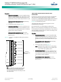
CPU circuit card P/N 506153 is to be installed in the
586505000/586505500 LMS1000 Expansion Cabinet(s)
or 582140000/582140001/582126100 Secondary
Bay(s).
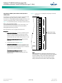
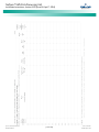
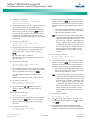
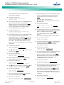
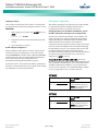
Installing the CPU Circuit Card(s)
Refer to the following procedure, and install the CPU circuit card(s)
into the respective mounting position of the
586505000/586505500 LMS1000 Main and Expansion Cabinet(s)
or 582140000/582140001/582126100 Power System Primary and
Secondary Power Bays.
PROCEDURE:
4.
Slide the CPU circuit card into its mounting location,
ensuring the rear edge connector is firmly seated.
5.
Secure the circuit card by tightening the retaining screw
located on the circuit card assembly (for the Main CPU
card, this is also the RS-232 Connector Grounding
Screw). In a 582140000/582140001/582126100 Power
System, note that if a modem is installed, it also contains
a bracket with a retaining screw.
6.
When all circuit cards have been installed, remove the
grounding wrist strap.
7.
After all electrical connections are made (as described
later), close the cabinet door and secure with the two
captive fasteners (arrow on fastener points towards
outside of cabinet). In a
582140000/582140001/582126100 Power System,
close the bay's front door.
8.
Save several of the static protective bags that the circuit
cards were shipped in. If a circuit card is ever required to
be removed from the system, it should immediately be
placed in a static protective bag.
Note: Refer to Figure 2 as this procedure is performed.
1.
586505000/586505500 LMS1000 Cabinet: To access the
circuit card mounting position, rotate the two captive
fasteners on the front of the cabinet until the arrow on
the fastener points up or down, and pivot the door open.
or
582140000/582140001/582126100 Power System:
Open the bay's front door to access the CPU circuit card
mounting positions.
2.
Connect an approved grounding strap to your wrist.
Attach the other end to a suitable ground.
3.
Unpack the CPU circuit card. CPU circuit card P/N
514024 is to be installed in the 586505000/586505500
LMS1000 Main Cabinet. CPU circuit card P/N 521185 is
to be installed in the
582140000/582140001/582126100 Primary Power Bay.
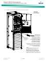
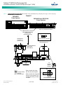
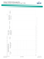
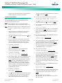
Figure 2. Installing the CPU Circuit Card (Main Cabinet shown, Expansion Cabinet similar) (cont'd on next page)
586505000
Main Cabinet
(586505500 Similar)
CPU Circuit Card
P/N 514024 (Main)
P/N 506153 (Expansion)
Spec. No: 58650500, 586505500
Model No: LMS1000
RS-232 Connector
Grounding Screw
(Main Cabinet Only)
[7 of 149]
Code: Section 5879
Issue BA, April 7, 2014
NetSure™ LMS Data Processing Unit
Installation Instructions, Section 5879 (Issue BA, April 7, 2014)
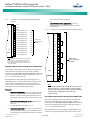
Figure 2. Installing the CPU Circuit Card (Primary Power Bay shown, Secondary Power Bay similar) (cont'd from previous page)
582126100
Primary and
Secondary Bays
582140001
Primary and
Secondary Bays
MONITORING AND
CONTROL SECTION
582140000
Primary and
Secondary Bays
POWER
FA
* ETHERNET
* Main
Bay
Only
3A 3A 3A
CAN BUS
* RS-485
ECH 1
ECH 2
* TEMP
ECH 3
L D M
M S C
S M A
F1 F2 F3
Front door assembly removed
in illustrations for clarity.
Primary LMS
CPU Circuit Card
(P/N 521185)
Spec. No: 58650500, 586505500
Model No: LMS1000
[8 of 149]
Secondary LMS
CPU Circuit Card
(P/N 506153)
Code: Section 5879
Issue BA, April 7, 2014
NetSure™ LMS Data Processing Unit
Installation Instructions, Section 5879 (Issue BA, April 7, 2014)
and sets the input to either monitor 50 mv and 100
mv DC shunt inputs, 0-60 volt DC inputs, or 20 ma
current loop inputs. Refer to Figure 4, and set each
jumper for the type of input to be monitored.
Installing Input/Output (I/O) Circuit Cards
Refer to the following procedure, and install the I/O circuit card(s)
into the respective mounting positions of the
586505000/586505500 LMS1000 Main and Expansion Cabinet(s)
or 582140000/582140001/582126100 Power System Primary and
Secondary Power Bay(s), as required.
6.
If you are installing an eight input binary circuit card,
make the following jumper adjustments.
a.
Note that in 582140000, 582140001, and 582126100 Power
Systems, an LMS CPU circuit card must be installed in a bay that is
to be populated with LMS I/O circuit card(s). LMS I/O circuit card
mounting positions are provided inside the
582140000/582140001/582126100 bays.
PROCEDURE:
Note: Refer to Figure 3 through Figure 6 as this procedure is
performed.
1.
586505000/586505500 LMS1000 Cabinet: To access the
circuit card mounting position, rotate the two captive
fasteners on the front of the cabinet until the arrow on
the fastener points up or down, and pivot the door open.
or
582140000/582140001/582126100 Power System:
Open the bay's front door to access the CPU circuit card
mounting positions.
2.
Connect an approved grounding strap to your wrist.
Attach the other end to a suitable ground.
3.
582140000/582140001/582126100 Power System:
Loosen the two screws securing the circuit card retaining
angle, and slide the retaining angle down.
4.
Unpack the LMS1000 I/O circuit card(s) to be installed.
Note: A maximum of six 12-input analog circuit cards can be
installed in the 586505000/586505500 Main Cabinet or
582140000/582140001/582126100 Primary Power Bay.
DO NOT install 12-input analog circuit cards in
586505000/586505500 Expansion Cabinets or
582140000/582140001/582126100 Secondary Bays.
If you are installing a four input analog circuit card, make
the following jumper adjustments.
a.
Four jumpers are provided on the four input analog
circuit card. Each jumper is associated to an input
Spec. No: 58650500, 586505500
Model No: LMS1000
[9 of 149]
If you are installing a four output (Form-C) relay circuit
card, make the following jumper adjustment.
a.
8.
Four (4) Input Analog Circuit Card (P/N 506336)
Eight (8) Input Analog Circuit Card (P/N 514528)
Twelve (12) Input Analog Circuit Card (P/N 520838)
Eight (8) Input Temperature Circuit Card (P/N 506333)
Four (4) Input Binary Circuit Card (P/N 506332)
Eight (8) Input Binary Circuit Card (P/N 506334)
Four (4) Output Form-C Relay Circuit Card (P/N 506335)
5.
7.
Eight jumpers are provided on the eight input binary
circuit card. Each jumper is associated to an input.
The second connection point for each binary input is
determined by the placement of the appropriate
jumper. These jumpers are factory set to the "-BAT"
position. For each binary input, refer to Figure 5 and
place the appropriate jumper either in the "+BAT" or
"-BAT" connection position. Refer to "Eight Input
Binary Circuit Card Connections, P/N 506334" in this
section for a description of the connection made by
the placement of these jumpers.
A jumper is provided on the four output (Form-C)
relay circuit card. The placement of this jumper
enables or disables the commands SET RLY (Set
Relay) and CLR RLY (Clear Relay). Refer to Figure 6
and set this jumper per site requirements.
Each I/O circuit card can be installed in any of the circuit
card mounting positions in any cabinet or bay, but install
circuit cards from left to right, in the next available empty
mounting position (as viewed from the front of the
cabinet or bay). DO NOT SKIP SLOTS. Circuit cards are
installed in the cabinet or bay with the component side
facing the left as viewed from the front. Slide the circuit
card(s) into its mounting location, ensuring the rear edge
connector is firmly seated.
Note: In 582140000/582140001/582126100 Power Systems,
the recommended method is to populate LMS
Input/Output circuit cards from left to right, and MCA
Customer Alarm Relay circuit cards from right to left.
9.
586505000/586505500 LMS1000 Cabinet: If a
temperature circuit card(s) has been installed, attach the
green wire connected to the circuit card(s) to one of the
grounding studs provided inside the cabinet. Refer to
Figure 3 for location. Place the lug of the green wire
below the flat washer provided on the grounding stud.
Replace the lock washer and resecure the nut.
582140000/582140001/582126100 Power System: If a
Temperature circuit card(s) has been installed, attach the
green wire connected to the circuit card(s) to one of the
Code: Section 5879
Issue BA, April 7, 2014
NetSure™ LMS Data Processing Unit
Installation Instructions, Section 5879 (Issue BA, April 7, 2014)
grounding studs provided inside the bay. Refer to Figure
3 for location. Place the lug of the green wire below the
bottom nut. Tighten the top nut down to lock the
bottom nut.
10. Supplied with your system documentation is an I/O
circuit card label sheet (P/N 520538). These labels allow
circuit card identification without removing a circuit card.
Apply the appropriate labels to the sheetmetal below
each installed I/O circuit card.
11. 582140000/582140001/582126100 Power System:
When all circuit cards have been installed, slide the circuit
card retaining angle up and secure by tightening the two
screws.
12. When all circuit cards have been installed, remove the
grounding wrist strap.
13. After all electrical connections are made (as described
later), close the cabinet door and secure with the two
captive fasteners (arrow on fastener points towards
outside of cabinet). In a
582140000/582140001/582126100 Power System,
close the bay's front door.
14. Save several of the static protective bags that the circuit
cards were shipped in. If a circuit card is ever required to
be removed from the system, it should immediately be
placed in a static protective bag.
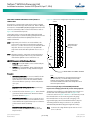
Figure 3. Installing the I/O Circuit Cards (cont'd on next page)
586505000
Main or Expansion Cabinet
(586505500 Similar)
Temperature
Circuit Card
Grounding Stud
Location*
* Note:
Two Grounding Studs are Provided. Each
Grounding Stud Contains a Flat Washer,
Lock Washer, and Nut. If a Temperature
Circuit Card is Installed, Attach the Green
Wire from the Circuit Card to One of the
Grounding Studs below the Flat Washer.
Replace the Lock Washer and Resecure the Nut.
Spec. No: 58650500, 586505500
Model No: LMS1000
I/O Circuit Card
Mounting Positions
Temperature
(Install I/O Circuit Cards
Circuit Card
from Left to Right
Grounding Stud
with Component Side
Location*
of Circuit Card Facing the
Left as Viewed from the Front.
DO NOT SKIP SLOTS.)
[10 of 149]
Code: Section 5879
Issue BA, April 7, 2014
NetSure™ LMS Data Processing Unit
Installation Instructions, Section 5879 (Issue BA, April 7, 2014)
Figure 3. Installing the I/O Circuit Cards (cont'd from previous page, cont’d on next page)
582140000
Power System
LMS Input/Output
(I/O) Circuit Card
Temperature
Circuit Card
Grounding Stud
Locations*
4-Input Analog, P/N 506336
8-Input Analog, P/N 514528
12-Input Analog, P/N 520838
8-Input Temperature, P/N 506333
4-Input Binary, P/N 506332
8-Input Binary, P/N 506334
4-Output Relay, P/N 506335
Install LMS I/O Circuit Cards from Left to Right
with Component Side of Circuit Card Facing
the Left as Viewed from the Front.
DO NOT SKIP SLOTS.
* Note:
Two grounding studs are provided. Each
grounding stud contains two nuts. If a
Temperature circuit card is installed, attach
the Green Wire from the circuit card to one
of the grounding studs, below the bottom nut.
Tighten the top nut down to lock the bottom nut.
Spec. No: 58650500, 586505500
Model No: LMS1000
[11 of 149]
Code: Section 5879
Issue BA, April 7, 2014
NetSure™ LMS Data Processing Unit
Installation Instructions, Section 5879 (Issue BA, April 7, 2014)
Figure 3. Installing the I/O Circuit Cards (cont'd from previous page)
582140001
Primary and
Secondary Bays
582126100
Primary and
Secondary Bays
MONITORING AND
CONTROL SECTION
POWER
FA
* ETHERNET
* Main
Bay
Only
* RS-485
ECH 1
Temperature
Circuit Card
Seven-Slot Card Cage
Grounding Stud
for MCA Customer Alarm
Locations* Relay Circuit Cards and/or LMS
Input/Output (I/O) Circuit Cards
3A 3A 3A
CAN BUS
ECH 2
* TEMP
ECH 3
L D M
M S C
S M A
F1 F2 F3
Temperature
Circuit Card
Grounding Stud
Locations*
LMS Input/Output
(I/O) Circuit Card
Front door assembly removed
in illustrations for clarity.
* Note:
Two grounding studs are provided. Each
grounding stud contains two nuts. If a
Temperature circuit card is installed, attach
the Green Wire from the circuit card to one
of the grounding studs, below the bottom nut.
Tighten the top nut down to lock the bottom nut.
Spec. No: 58650500, 586505500
Model No: LMS1000
Seven-Slot Card Cage
for MCA Customer Alarm
Relay Circuit Cards and/or LMS
Input/Output (I/O) Circuit Cards
4-Input Analog, P/N 506336
8-Input Analog, P/N 514528
12-Input Analog, P/N 520838
8-Input Temperature, P/N 506333
4-Input Binary, P/N 506332
8-Input Binary, P/N 506334
4-Output Relay, P/N 506335
Install LMS I/O Circuit Cards from Left to Right
with Component Side of Circuit Card Facing
the Left as Viewed from the Front.
DO NOT SKIP SLOTS.
[12 of 149]
Code: Section 5879
Issue BA, April 7, 2014
NetSure™ LMS Data Processing Unit
Installation Instructions, Section 5879 (Issue BA, April 7, 2014)
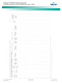
Figure 4. Jumper Location, Four Input Analog Circuit Card, P/N 506336
16
15
3 2 1
14
J2
13
12
3 2 1
Jumper
Input
J2
A4
J102
A3
J202
A2
J302
A1
11
J102
10
3 2 1
J202
TB1
9
8
7
6
3 2 1
J302
5
4
3
2
506336
1
Place jumper ONLY on pin 1 for 50 mv and 100 mv shunt inputs.
Connect inputs to terminals designated "Small Signal".
3 2 1
Place jumper on pins 1 and 2 for 0-60 volt DC inputs.
Connect inputs to terminals designated "Large Signal".
3 2 1
Place jumper on pins 2 and 3 for 20 ma current loop inputs.
Connect inputs to terminals designated "Small Signal".
3 2 1
Spec. No: 58650500, 586505500
Model No: LMS1000
[13 of 149]
+
A4
+
A4
+
A3
+
A3
+
Large
Signal
Small
Signal
Large
Signal
Small
Signal
A2
Large
Signal
A2
Small
Signal
A1
Large
Signal
A1
Small
Signal
+
+
+
Code: Section 5879
Issue BA, April 7, 2014
NetSure™ LMS Data Processing Unit
Installation Instructions, Section 5879 (Issue BA, April 7, 2014)
Figure 5. Jumper Location, Eight Input Binary Circuit Card, P/N 506334
3 2 1
Input
J8
B8
J7
B7
J6
B6
J5
J4
B4
J3
B3
J2
B2
J1
B1
14
J7
13
3 2 1
12
J6
11
3 2 1
J5
B5
3 2 1
10
TB1
J4
3 2 1
J3
3 2 1
J2
3 2 1
J1
506334
Place jumper on pins 1 and 2
to complete a -BAT
connection for this input
Spec. No: 58650500, 586505500
Model No: LMS1000
3 2 1
Place jumper on pins 2 and 3
to complete a +BAT
connection for this input
[14 of 149]
-BAT
15
J8
Jumper
+BAT
16
3 2 1
9
8
B8
7
B7
B6
6
5
B5
4
B4
B3
3
2
B2
1
B1
3 2 1
Code: Section 5879
Issue BA, April 7, 2014
NetSure™ LMS Data Processing Unit
Installation Instructions, Section 5879 (Issue BA, April 7, 2014)
Figure 6. Jumper Location, Four Output (Form-C) Relay Circuit Card, P/N 506335
16
15
14
13
12
To disable the commands SET RLY and CLR RLY,
place the jumper provided on the two pins of J1.
11
10
TB1
J1
9
8
To enable the commands SET RLY and CLR RLY,
remove the jumper from the two pins of J1.
The jumper may be stored on ONE of the pins.
7
6
5
4
3
2
506335
Spec. No: 58650500, 586505500
Model No: LMS1000
1
[15 of 149]
Code: Section 5879
Issue BA, April 7, 2014
NetSure™ LMS Data Processing Unit
Installation Instructions, Section 5879 (Issue BA, April 7, 2014)
Making Electrical Connections
Wiring Considerations
All electrical connections are made without DC input power
applied to the system.
All wiring and branch circuit protection should follow the current
edition of the American National Standards Institute (ANSI)
approved National Fire Protection Association's (NPFA) National
Electrical Code (NEC), and applicable local codes. For operation in
countries where the NEC is not recognized, follow applicable
codes. For field wiring, use wires suitable for at least 75°C.
Observe the Following Admonishment
Danger
Danger
Danger
DANGER! This product requires Safety Extra-Low
Voltage (SELV) Inputs. A SELV input (based on the
safety requirements for Information Technology
Equipment Standards, such as UL1950, IEC 950) is a
secondary circuit which is so designed and protected
that under normal and single-fault conditions, the
voltage between any two paths of the SELV circuit or
circuits and for Class 1 equipment (provided with a
protective earthing conductor from the building),
between any one such part and the equipment
protective earthing terminal does not exceed a safe
value (42.4 V peak or 60 Vdc under normal conditions).
It is separated from the primary or mains supply by
Double (insulation comprising both Basic and
Supplementary insulation) or Reinforced insulation (a
single insulation system which provides a degree of
protection against electric shock equivalent to Double
insulation).
DANGER! DO NOT apply power to the system until all
electrical connections have been completed and
checked.
DANGER! To minimize voltage potentials inside the
cabinet during installation, connect leads to the cabinet
first, before connecting leads to the external source.
Spec. No: 58650500, 586505500
Model No: LMS1000
586505000/586505500 Main and Expansion Cabinet
Grounding Connection (586505000/586505500 only)
A frame ground stud is provided on the rear of the cabinet. Refer
to Figure 7 for location. Recommended wire size is 14 gauge.
Recommended torque is 23 in-lbs. Provide a grounding
connection to this stud.
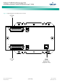
586505000/586505500 Main and Expansion Cabinet
DC Input Power Connection (586505000/586505500 only)
DC input power connections are made to the two-position
terminal block located on the rear of the cabinet. Connections
should be made using 18 gauge or 16 gauge stranded wire. The
ungrounded input lead should be fused at 3 amperes.
Refer to Figure 7 for DC input power terminal block location and
identification. The DC input power terminal block accepts a wire
size in the range of 22 to 14 gauge. Recommended torque is 12
in-lbs.
Connect the positive DC input lead to the terminal designated +
(positive).
Connect the negative DC input lead to the terminal designated (negative).
[16 of 149]
Code: Section 5879
Issue BA, April 7, 2014
NetSure™ LMS Data Processing Unit
Installation Instructions, Section 5879 (Issue BA, April 7, 2014)
Figure 7. 586505000/586505500 Terminal Location and Identification (cont’d on next page)
586505000
(586505500 similar)
J4
(located
behind
bracket)
CPU Circuit Card
in Main Cabinet
J4
1
2
3
4
5
6
External
Hardware Fail Alarm
Spec. No: 58650500, 586505500
Model No: LMS1000
[17 of 149]
Note:
Relay Contacts are Energized
During Normal Operation and
Deenergized During an Alarm
Condition. Relay Contacts are
Shown with the Relay Deenergized.
Code: Section 5879
Issue BA, April 7, 2014
NetSure™ LMS Data Processing Unit
Installation Instructions, Section 5879 (Issue BA, April 7, 2014)
Figure 7. 586505000/586505500 Terminal Location and Identification (cont'd from previous page, cont’d on next page)
586505000
(586505500 similar)
Front View
(Main Cabinet)
RS-232
(Located on CPU Circuit Card,
Accessible through Front Door)
9-Pin Female D-Type Connector
5
1
9 6
For Local Terminal Connection
List 85:
AC Analyzer Port
or
List 86:
TL1/X.25 Port
or
List 88:
Local Port Redirection
or
List 79:
Gateway Port
List 60/61:
LMS Front Panel Display Port
or
List 84:
External GPS Modem Port
RS-232/422
OEM 2 Port*
* Communications Ports
9-Pin Female D-Type Jacks
Always Vortex
(VPS) Port
and
List 80:
Door Access Controller Port
(use 'Y' cable to also connect
VPS to same port)
RS-232
OEM 1 Port*
Shelf Grounding
Stud (10-32)
RS-485 (Vortex)
OEM 3 Port*
RJ-45
System
Network
Ports
(Expansion
Ports)
DC Input
586505000
(586505500 similar)
Rear View
(Main Cabinet)
Access Opening and Cable Channel
for Connections to I/O Circuit Cards
and External CPU/Hardware Fail Alarms
Spec. No: 58650500, 586505500
Model No: LMS1000
[18 of 149]
RJ-45
ETHERNET
Port
RJ-11
Phone Line
(active only if
modem installed)
Code: Section 5879
Issue BA, April 7, 2014
NetSure™ LMS Data Processing Unit
Installation Instructions, Section 5879 (Issue BA, April 7, 2014)
Figure 7. 586505000/586505500 Terminal Location and Identification (cont'd from previous page)
586505000
(586505500 similar)
Front View
(Expansion Cabinet)
Shelf Grounding
Stud (10-32)
RJ-45
System
Network Ports
(Expansion Ports)
DC Input
586505000
(586505500 similar)
Rear View
(Expansion Cabinet)
Access Opening and Cable Channel
for Connections to I/O Circuit Cards
Spec. No: 58650500, 586505500
Model No: LMS1000
[19 of 149]
Code: Section 5879
Issue BA, April 7, 2014
NetSure™ LMS Data Processing Unit
Installation Instructions, Section 5879 (Issue BA, April 7, 2014)
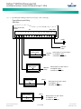
Figure 8. 582140000/582140001/582126100 LMS Terminal Location and Identification (cont'd on next page)
582140001
Power System
582126100
Power System
582140000
Power System
MONITORING AND
CONTROL SECTION
MONITORING AND
CONTROL SECTION
Spec. No. 582140000 shown,
Spec. No. 582126100 similar.
See
Detail B
See
Detail C
LMS Local Port
(on outside of front door
on MCA Control Panel,
Primary Bay only)
(See Detail A)
Spec. No: 58650500, 586505500
Model No: LMS1000
See
Detail D
See Detail B for
LMS Ethernet Port,
LMS RS-485 Port,
LMS Network Ports
See
Detail B
See
Detail C
See Detail C for
LMS Modem Port,
LMS CPU/Hardware
Fail Alarm Connector,
LMS Gateway Port
[20 of 149]
See
Detail D
See Detail D for
LMS Input/Output (I/O)
Circuit Cards
Code: Section 5879
Issue BA, April 7, 2014
NetSure™ LMS Data Processing Unit
Installation Instructions, Section 5879 (Issue BA, April 7, 2014)
Figure 8. 582140000/582140001/582126100 LMS Terminal Location and Identification (cont'd from previous page, cont'd on next page)
Detail A
LMS LOCAL PORT (USB)
(active only if optional LMS installed)
(Provided via a USB to RS-232 Port Adapter Unit)
582140000
Power System
Primary Bay
Mating Connector in
Power System Wiring Harness
5
1
9 6
Mating Connector
in Power System Wire Harness
(9-Pin Female D-Type Jack)
If required to connect to a serial
port, disconnect the factory plug to
the “USB to RS-232 Port Adapter
Unit” and connect to this plug.
582140001 and 582126100
Power System Primary Bay
MINOR
TEST EQ
FUNCTION
SELECT
ENTER
NO
FUNCTION
SET
RS-232
5
LMS LOCAL PORT (RS-232)
(active only if optional LMS installed)
Spec. No: 58650500, 586505500
Model No: LMS1000
[21 of 149]
1
9 6
9-Pin Female D-Type Jack
Code: Section 5879
Issue BA, April 7, 2014
NetSure™ LMS Data Processing Unit
Installation Instructions, Section 5879 (Issue BA, April 7, 2014)
Figure 8. 582140000/582140001/582126100 LMS Terminal Location and Identification (cont'd from previous page, cont'd on next page)
Detail B
582140000 and 582126100
Power Systems
LMS Ethernet Port
(Primary Bay Only)
(RJ-45)
Spec. No. 582140000 shown,
Spec. No. 582126100 similar.
LMS
OEM Port
(RS-485)
(Primary Bay
Only)
LMS
Network
Ports
(Echelon)
(RJ-45)
Primary Bay
Secondary Bay
LMS Network Cable
(BLUE Cable)
5
1
9 6
9-Pin Female D-Type Jack
Secondary Bay
LMS Network Cable
(BLUE Cable)
LMS NETWORK PORT
Typical Interconnections
Secondary Bay
LMS Network Cable
(BLUE Cable)
LMS Network Cable
(BLUE Cable)
LMS Network Cable
(BLUE Cable)
LMS Expansion Assembly
LMS Expansion Assembly
Spec. No: 58650500, 586505500
Model No: LMS1000
[22 of 149]
Code: Section 5879
Issue BA, April 7, 2014
NetSure™ LMS Data Processing Unit
Installation Instructions, Section 5879 (Issue BA, April 7, 2014)
Figure 8. 582140000/582140001/582126100 LMS Terminal Location and Identification (cont'd from previous page, cont'd on next page)
Detail B
582140001
Power System
LMS Ethernet Port
(Primary Power Bay Only)
(RJ-45)
LMS OEM Port
(RS-485)
(Primary Power
Bay Only)
LMS Network Ports
(Echelon) (RJ-45)
Primary Bay
Secondary Bay
LMS Network Cable
(BLUE Cable)
5
1
9 6
9-Pin Female D-Type Jack
Secondary Bay
LMS Network Cable
(BLUE Cable)
LMS NETWORK PORT
Typical Interconnections
Secondary Bay
LMS Network Cable
(BLUE Cable)
LMS Network Cable
(BLUE Cable)
LMS Network Cable
(BLUE Cable)
LMS Expansion Assembly
LMS Expansion Assembly
Spec. No: 58650500, 586505500
Model No: LMS1000
[23 of 149]
Code: Section 5879
Issue BA, April 7, 2014
NetSure™ LMS Data Processing Unit
Installation Instructions, Section 5879 (Issue BA, April 7, 2014)
Figure 8. 582140000/582140001/582126100 LMS Terminal Location and Identification (cont'd from previous page, cont'd on next page)
Detail C
582140001
Power System
582140000 and 582126100
Power Systems
Spec. No. 582140000 shown,
Spec. No. 582126100 similar.
LMS Monitoring System
Main CPU Circuit Card
(P/N 521185)
(Primary Bay Only)
5
1
9 6
9-Pin Female D-Type Jack
LMS Modem
Port (RJ-11)
(Phone Line)
RS-232
LMS Gateway Port
Piggy-Back Modem
Circuit Card
(P/N 508951)
J4
(located
behind
bracket)
NO
Notes
NC = Normally Closed
C = Common
NO = Normally Open
Spec. No: 58650500, 586505500
Model No: LMS1000
Relay contacts are shown
with the relay deenergized.
Relay contacts are energized
during normal operation and
deenergized during an alarm
condition.
[24 of 149]
J4
1
2
3
4
C
5
NC
6
External
CPU/Hardware Fail Alarm
Code: Section 5879
Issue BA, April 7, 2014
NetSure™ LMS Data Processing Unit
Installation Instructions, Section 5879 (Issue BA, April 7, 2014)
Figure 8. 582140000/582140001/582126100 LMS Terminal Location and Identification (cont'd from previous page)
Detail D
582140001
Power System
582140000 and 582126100
Power Systems
Spec. No. 582140000 shown,
Spec. No. 582126100 similar.
Seven-Slot Card Cage for MCA
Customer Alarm Relay Circuit Cards
and/or LMS Input/Output (I/O) Circuit Cards
Available LMS I/O Circuit Cards
4-Input
Analog
(P/N 506336)
Spec. No: 58650500, 586505500
Model No: LMS1000
8-Input
Analog
(P/N 514528)
12-Input
Analog
(P/N 520838)
8-Input
Temperature
(P/N 506333)
[25 of 149]
4-Input
Binary
(P/N 506332)
8-Input
Binary
(P/N 506334)
4-Output
Relay
(P/N 506335)
Code: Section 5879
Issue BA, April 7, 2014
NetSure™ LMS Data Processing Unit
Installation Instructions, Section 5879 (Issue BA, April 7, 2014)
582140000/582140001/582126100 Power System: If
no more connections are to be made inside the bay, close
the front door.
External CPU/Hardware Fail Alarm Connections
The external CPU/hardware fail alarm connections are made to
terminal block J4 located on the CPU circuit card installed in the
586505000/586505500 LMS1000 Main Cabinet or
582140000/582140001/582126100 Primary Power Bay.
Recommended wire size is 22 gauge for loop lengths up to 200
feet, and 18-20 gauge for loop lengths over 200 feet. Stranded
twisted pair wire is recommended. To minimize voltage potentials
inside the cabinet during installation, alarm relay leads should be
connected at the cabinet or bay first. Refer to Figure 7 or Figure 8
for terminal block location.
Local Terminal Port Connections
586505000/586505500: The local terminal is connected to the 9pin female D-type jack located on the front of the Main Cabinet,
labeled "RS-232". Refer to Figure 7 for jack location. Refer to Table
1 for jack configuration. This jack is configured as a DCE (Data
Communication Equipment).
Note: When 586505000/586505500 List 88 is ordered, the port on
the front of the 586505000/586505500 cabinet is inactive,
and the local port is redirected to OEM1 located on the rear of
the cabinet. List 88 cannot be used in conjunction with
586505000/586505500 List 79 (Gateway Port), List 85 (AC
Analyzer Interface), or List 86 (TL1/X.25).
These leads enter the 586505000/586505500 LMS1000 cabinet at
the rear of the cabinet and are routed through a cable channel
located on the bottom of the cabinet.
•
•
•
Terminal block J4 consists of two pieces snapped
together. The two pieces can be separated by gently
pulling the one half from the other. This feature
facilitates circuit card wiring and circuit card
replacement, if required.
Wires are connected to the terminals of J4 by inserting
the stripped wire into the wire opening, and then
tightening the screw. The wires should be checked for
proper installation by gently attempting to pull the wires
from the terminal.
Terminal block J4 accepts a wire size in the range of 28 to
16 gauge. Recommended torque is 4 in-lbs.
PROCEDURE:
1.
2.
3.
586505000/586505500 LMS1000 Main Cabinet: To
access terminal block J4 located on the Main Cabinet CPU
circuit card, rotate the two captive fasteners on the front
of the cabinet until the arrow on the fastener points up or
down, and pivot the door open.
or
582140000/582140001/582126100 Power System:
Open the front door of the Primary Power Bay to access
the LMS Main CPU circuit card.
582140001/582126100: A 9-pin female D-type jack (labeled
"RS-232") is provided on the front door of the Primary Power Bay
(on the MCA Control Panel) for LMS local terminal connection.
Refer to Figure 8 for location. Refer to Table 1 for jack
configuration. This jack is configured as a DCE (Data
Communication Equipment).
582140000: The 9-pin female D-type jack (LMS RS-232 Local Port)
provided in the system wiring harness is factory connected to a
USB to RS-232 Port Adapter Unit. The USB to RS-232 Port Adapter
Unit is factory connected to the USB port provided on the front
door of the Primary Power Bay (on the MCA Control Panel) for LMS
local terminal connection. (A device driver CD is supplied with the
USB to RS-232 Port Adapter Unit. The proper driver must be
installed on the computer to be connected to the USB port.)
Note: If required to connect to a serial port, disconnect the factory
RS-232 jack from the “USB to RS-232 Port Adapter Unit” and
connect to this jack. Refer to Table 1 for jack configuration.
This jack is configured as a DCE (Data Communication
Equipment).
Table 1.
Local Port Pin Assignments (9-Pin Female D-Type Jack)
RS-232 Configured as DCE
Connect the external CPU/hardware fail alarm to
terminals 4 through 6 of J4. An open loop circuit is
provided between terminals 4 and 5 of J4, and a closed
loop circuit is provided between terminals 5 and 6 of J4
during a CPU/hardware fail alarm condition.
Port Pin Number
Application
1
-
-
2
Transmitted Data (TxD)
Output from System
586505000/586505500 LMS1000 Main Cabinet: If no
more connections are to be made inside the cabinet,
close the cabinet door and secure with the two captive
fasteners (arrow on fastener points towards outside of
cabinet).
or
Spec. No: 58650500, 586505500
Model No: LMS1000
[26 of 149]
Input/Output
3
Received Data (RxD)
Input to System
4
Data Set Ready (/DSR)
Output from System
5
Signal Ground (Gnd)
-
6
Data Terminal Ready
(/DTR)
Input to System
7
Clear to Send (/CTS)
Input to System
8
Request to Send (/RTS)
Output from System
9
-
Code: Section 5879
Issue BA, April 7, 2014
NetSure™ LMS Data Processing Unit
Installation Instructions, Section 5879 (Issue BA, April 7, 2014)
Gateway Port Connections (if Gateway Software Option is
installed)
Internal Modem Port Connections
The Gateway Software Option allows the LMS1000 to emulate a
“dumb” RS-232 asynchronous terminal interface. When installed,
user input through either a local or remote LMS1000 port is
directed to the customer equipment connected to the LMS1000
Gateway port.
Warning
The cable from the LMS1000 Gateway port to the customer
equipment must not exceed 50 feet. This cable must be provided
by the customer.
586505000/586505500: In the 586505000/586505500 system,
the Gateway port is provided via the OEM1 port. Refer to Figure 7
for port location. Refer to Table 3 for port pin assignments. See
"OEM1 Port Connections (if required) (586505000/586505500
Only)" later in these instructions.
582140000/582140001/582126100: In the
582140000/582140001/582126100 system, the Gateway port is
provided via the port located on the front of the LMS CPU circuit
card installed in the Primary Power Bay. This is a 9-pin female Dtype jack (RS-232). Refer to Figure 8 for location. Refer to Table 2
for port pin assignments.
Table 2.
Port Located on Front of Main LMS CPU Circuit Card
Installed in Primary Power Bay (9-Pin Female D-Type Jack)
RS-232 Configured as DCE
Port Pin Number
Application
Input/Output
1
-
-
2
Transmitted Data (TxD)
Output from System
3
Received Data (RxD)
Input to System
4
Data Set Ready (/DSR)
Output from System
5
Signal Ground (Gnd)
-
6
Data Terminal Ready
(/DTR)
Input to System
7
Clear to Send (/CTS)
Input to System
8
Request to Send (/RTS)
Output from System
9
-
-
WARNING! The intra-building port(s) of the equipment
or subassembly is suitable for connection to intrabuilding or unexposed wiring or cabling only. The intrabuilding port(s) of the equipment or subassembly MUST
NOT be metallically connected to interfaces that
connects to the OSP or its wiring. These interfaces are
designed for use as intra-building interfaces only (Type
2 or Type 4 ports as described in GR-1089-CORE, Issue
4) and require isolation from the exposed OSP cabling.
The addition of Primary Protectors is not sufficient
protection in order to connect these interfaces
metallically to OSP wiring. Use shielded phone cable
(grounded at both ends). Note that the LMS1000 RJ-11
jack is connected to chassis ground.
586505000/586505500: If a modem circuit card is installed, the
remote communications phone line connection is made to the
RJ-11 jack located on rear of the Main Cabinet. Refer to Figure 7 for
RJ-11 location.
582140000/582140001/582126100 System: An internal modem
circuit card may be installed on the LMS Main CPU circuit card. The
modem circuit provides an RJ-11 phone jack for customer phone
line connection. Refer to Figure 8 for location.
Ethernet Port Connections (10M)
Note: The LMS supports an Ethernet connection speed up to
10mbps.
Note: Also used for the TL1 Port if 'TL1 over Ethernet' software option
installed.
586505000/586505500: The Main Cabinet is connected to the
customer's network running TCP/IP via the RJ-45 jack located on
the rear of the cabinet, labeled "ETHERNET". Refer to Figure 7 for
jack location. Jack pin configuration is a standard Ethernet
scheme, twisted pair (T568A or T568B), 10BaseT, and half duplex.
Use shielded Ethernet cable (grounded at both ends). Note that
the LMS1000 RJ-45 jack is connected to chassis ground.
582140000/582140001/582126100: An RJ-45 jack (labeled
"ETHERNET") is provided inside the Primary Power Bay (near the
LMS Main CPU circuit card) for connection into a customer's
network running TCP/IP. Refer to Figure 8 for location. Jack pin
configuration is a standard Ethernet scheme, twisted pair (T568A
or T568B), 10BaseT, and half duplex.
Use shielded Ethernet cable (grounded at both ends). Note that
the LMS RJ-45 jack is connected to chassis ground.
Spec. No: 58650500, 586505500
Model No: LMS1000
[27 of 149]
Code: Section 5879
Issue BA, April 7, 2014
NetSure™ LMS Data Processing Unit
Installation Instructions, Section 5879 (Issue BA, April 7, 2014)
OEM1 Port Connections (if required) (586505000/586505500
Only)
Connections to the OEM1 port are made to a 9-pin female D-type
jack located on the rear of the Main Cabinet, labeled "OEM1
(RS-232)". Refer to Figure 7 for jack location. Refer to Table 3 for
jack configuration. The port's function is determined by the
LMS1000 Software Options or LMS1000 Specialty Interfaces
installed.
Local Port Redirection (if 586505000/586505500 List 88
installed), (Cannot be used in conjunction with
586505000/586505500 List 79 [Gateway Port], List 85 [AC
Analyzer Interface], or List 86 [TL1/X.25].)
AC Analyzer Interface Port (if 586505000/586505500 List 85
installed), (Cannot be used in conjunction with
586505000/586505500 List 79 [Gateway Port], List 86
[TL1/X.25], or List 88 [Local Port Redirection].)
Connect the OEM1 Port to a Dossena AC Analyzer Model MV3DL.
OEM1 port pin assignments are as shown in Table 3.
Table 3.
Port Pin Number
Application
1
-
-
2
Received Data (RxD)
Input to System
3
Transmitted Data (TxD)
Output from System
4
Data Terminal Ready
(/DTR)
Output from System
The port on the front of the cabinet is inactive, and the local port is
redirected to OEM1 located on the rear of the cabinet. Make local
terminal connection here, not to the front panel jack. OEM1 port
pin assignments are as shown in Table 3.
TL1/X.25 Port (if 586505000/586505500 List 86 installed),
(Cannot be used in conjunction with 586505000/586505500
List 79 [Gateway Port], List 85 [AC Analyzer Interface], or List
88 [Local Port Redirection].)
The OEM1 port provides asynchronous output for interfacing to a
network interface device (an X.25 PAD or similar device). Connect
the OEM1 port to a network interface device of a PSDN (Packet
Switched DATA Network). Maximum cable length from the
network device to the OEM1 port is 50 feet. The customer must
provide this cable. OEM1 port pin assignments are as shown in
Table 2-3.
A feature of the LMS1000 TL1/X.25 port is to provide customer
control of the port's output data flow. The output data flow is
enabled or disabled based on the state of a hardware handshake
signal. If this signal is present, the port's data flow is enabled. If a
hardware handshake signal is to be provided by the customer,
connect this signal to the LMS1000 TL1/X.25 port on Pin 8 "Clear to
Send (CTS)".
If a hardware handshake signal is not provided by the customer,
jumper Pin 7 "Request to Send (RTS)" to Pin 8 "Clear to Send (CTS)".
Warning
WARNING! The handshake signal is used to prevent
the system from transmitting reports when the
network connection is not available. If no handshake
signal is provided, reports will be transmitted
immediately upon alarm/errant occurrence and may
be lost if the network device is not ready to receive
them.
Spec. No: 58650500, 586505500
Model No: LMS1000
OEM1 Port Pin Assignments (9-Pin Female D-Type Jack)
RS-232 Configured as DTE
Input/Output
5
Signal Ground (Gnd)
-
6
Data Set Ready (/DSR)
Input to System
7
Request to Send (/RTS)
Output from System
8
Clear to Send (/CTS)
Input to System
9
-
-
Gateway Port (if 586505000/586505500 List 79 installed),
(Cannot be used in conjunction with 586505000/586505500
List 85 [AC Analyzer Interface], List 86 [TL1/X.25], or List 88
[Local Port Redirection].)
See "Gateway Port Connections" earlier in this document.
OEM2 Port Connections (if required) (586505000/586505500
Only)
Connections to the OEM2 port are made to a 9-pin female D-type
jack located on the rear of the Main Cabinet, labeled "OEM2
(RS-232/422)". Refer to Figure 7 for jack location. Refer to Table 4
and Table 5 for jack configuration. The port's function is
determined by the LMS1000 Software Options or LMS1000
Specialty Interfaces installed.
External Modem Interface Port (if 586505000/586505500 List
84 installed), (Cannot be used in conjunction with
586505000/586505500 List 60, 61, 62, or 63 [LMS1000 Front
Panel Display Option].)
Connect the OEM2 Port to an Enfora GPS Modem. OEM2 port pin
assignments are as shown in Table 4.
[28 of 149]
Code: Section 5879
Issue BA, April 7, 2014
NetSure™ LMS Data Processing Unit
Installation Instructions, Section 5879 (Issue BA, April 7, 2014)
Table 4.
OEM2 Port Pin Assignments (9-Pin Female D-Type Jack)
Software Selected for RS-232 Connection, Configured as
DTE
Port Pin Number
Application
Input/Output
1
Data Carrier Detect
(/DCD)
Input to System
2
Received Data (RxD)
Input to System
3
Transmitted Data (TxD)
Output from System
4
Data Terminal Ready
(/DTR)
Output from System
5
Signal Ground (Gnd)
-
6
Data Set Ready (/DSR)
Input to System
7
Request to Send (/RTS)
Output from System
8
Clear to Send (/CTS)
Input to System
9
-
-
Table 5.
OEM2 Port Pin Assignments (9-Pin Female D-Type Jack)
Software Selected for RS-422 Connection, Configured as
DTE
Port Pin Number
Application
Input/Output
1
Received Data (RxD-)
Input to System
2
Received Data (RxD+)
Input to System
3
Transmitted Data (TxD+)
Output from System
4
Transmitted Data (TxD-)
Output from System
5
Signal Ground (Gnd)
-
6
Handshake Out (HSO-)
Output from System
7
Handshake Out (HSO+)
Output from System
8
Handshake In (HSI+)
Input to System
9
Handshake In (HSI-)
Input to System
Note: At this time install the supplied ferrite cable clamp onto the
cable at any convenient location near the VPS/NPS.
VPS/NPS INTERFACE CABLE SPECIFICATIONS
LMS1000 is connected to the VPS/NPS with a multi-conductor
cable that is terminated on one end with a 9-pin male D-type plug,
and on the other end with an RJ-45 plug. These plugs mate with
the 9-pin female D-type VPS/NPS Port jack provided on LMS1000
(refer to Figure 7) and the appropriate RJ-45 jack provided on the
VPS/NPS.
A cable with the appropriate plugs attached to both ends may be
supplied, or a length of cable with two unconnected plugs may be
supplied, as ordered. If required, the installer is to assemble the
cable per these specifications and per site requirements.
The recommended cable is a category 5, four twisted pair
conductor, 24 gauge solid copper cable. Emerson Network Power
P/N 156202100. Belden P/N 1585AD15. If this cable is ordered
through Emerson Network Power, specify the required length in 5
feet increments. A six foot cable with appropriate plugs preattached is also available (P/N 421843500).
The required components necessary to terminate the cable are
provided in a kit offered by Emerson Network Power. The Emerson
Network Power part number of this kit is 483590800 and consists
of:
a.
One (1) RJ-45 plug. Emerson Network Power P/N
247809900. AMP P/N 557315.
b.
One (1) 9-pin male D-type plug. Emerson Network Power
P/N 247882220. AMP P/N 205204-4.
OEM3 Port Connections (if required) (586505000/586505500
Only)
c.
Four (4) snap-in crimp type contacts. Emerson Network
Power P/N 245381800. AMP P/N 66506-3.
This port always functions as a Vortex Power System (VPS) or
NETSURE Power System (NPS) Interface Port. The port may also
have other functions as determined by the LMS1000 Software
Options or LMS1000 Specialty Interfaces installed.
d.
One (1) cable clamp assembly kit. Emerson Network
Power P/N 247835712. AMP P/N 207908-1.
Vortex Power System (VPS) or NETSURE Power System (NPS)
Port
VPS/NPS INTERFACE CABLE ASSEMBLY
Attach a plug to each end of the cable per Table 6, and the
following instructions.
Attaching RJ-45 Plug
A cable is connected between the 9-pin female D-type VPS/NPS
Port jack (labeled "OEM3 [VORTEX RS-485]") located on the rear of
the Main Cabinet, and the appropriate RJ-45 jack located on the
VPS/NPS cabinet. Refer to Figure 7 for location of the VPS/NPS
Port jack on the rear of the Main Cabinet. Refer to the VPS/NPS
documentation for location of the RJ-45 jack on the VPS/NPS.
Refer to the next section for cable specifications and assembly
instructions. Maximum cable length from LMS1000 to the
VPS/NPS is 4,000 feet.
Spec. No: 58650500, 586505500
Model No: LMS1000
[29 of 149]
1.
Trim and strip (0.5 - 0.56 inch) jacketed cable using
appropriate, commercially available tools.
Note: Do not strip insulated wires.
2.
Insert the wires completely into the RJ-45 plug. Visually
inspect the assembly to ensure proper routing of the
individual conductors. If using the recommended cable,
follow the color scheme shown in Table 6. Refer to Figure
9 for the pin numbering scheme of the RJ-45 plug.
Code: Section 5879
Issue BA, April 7, 2014
NetSure™ LMS Data Processing Unit
Installation Instructions, Section 5879 (Issue BA, April 7, 2014)
3.
Terminate the cable using appropriate crimp tool, AMP
P/N 2-231652-1 with die set AMP P/N 853400-1.
Figure 9. RJ-45 Plug
Attaching 9-Pin Male D-Type Plug
1.
Trim and strip (0.75 inch) jacketed cable using
appropriate, commercially available tools.
2.
Attach the crimp type contacts to the wires of the cable
using a crimp tool, AMP P/N 90302-1, or 90312-1, or
404494-7. (Strip the wires approximately one quarter of
an inch.) If using the recommended cable, follow the
color scheme shown in Table 2-6.
3.
Insert the crimp type contacts (with wires attached) into
the plug housing using an insertion/extraction tool, AMP
P/N 91067-2. A single ended insertion tool is also
available, AMP P/N 91234-1.
4.
Assemble the retaining clips onto the receptacle flanges
with the threaded hole facing toward the wire side of the
connector.
1
8
Rear View
Figure 10. Assembling Cable Clamp Assembly
UNUSED SLOT
Attaching Cable Clamp Assembly
1.
A carrier strip with strain-relief gates is packaged with
each assembly. Remove the curved gate and large blank
gate from the carrier strip.
2.
Insert the curved gate into the cable clamp slot as shown
in Figure 10. Insert the large blank gate into the unused
slot.
3.
Insert the plug into the clamp with the longer row of
contacts in the bottom (portion of cable clamp which is
slotted for cable). Position the cable in the strain relief
channel.
4.
CABLE CLAMP ASSEMBLY
CABLE CLAMP SLOT
LARGE BLANK GATE
CURVED GATE
Position the cable over the curved gate and close the
cable clamp.
5.
Note:
Cable clamp assembly
may be used for 90° mounting
by exchanging BLANK GATE
and CURVE GATE.
Thread the screws into the holes in the cable clamp and
tighten them to complete the assembly.
Table 6.
Isometric View
PLUG
VPS/NPS Interface Cable Wiring
Recommended
Wire Color
From RJ-45 Jack
Located on VPS/NPS
Pin Number
To 9-Pin D-Type Jack
Located on LMS1000
Pin Number
white/blue stripe
1
3
2
blue
2
white/orange stripe
3
-
orange
4
-
white/green stripe
5
-
green
6
-
white/brown stripe
7
-
brown
8
5
Spec. No: 58650500, 586505500
Model No: LMS1000
[30 of 149]
Code: Section 5879
Issue BA, April 7, 2014
NetSure™ LMS Data Processing Unit
Installation Instructions, Section 5879 (Issue BA, April 7, 2014)
Door Access Controller (DAC) Port (if 586505000/586505500
List 80 installed)
Connect the OEM3 Port to a Desarrollos Digitales Door Access
Controller Model MKC-1. OEM3 port pin assignments are as shown
in Table 7.
Note: Recommended to use a Desarrollos Digitales Isolation Board
(Model DTP-1-485 / 96-DC24-T, E) between the DAC and
LMS1000.
If you need to also connect the LMS1000 to a Vortex Power System
or NETSURE Power System, customer must assemble a "Y" cable to
allow both the Door Access Controller and the Power System to be
connected to the LMS1000 OEM3 Port.
You will also have to connect an LMS1000 output relay to the
Access Door's electronic strike. This allows you to manually bypass
the Door Access Controller to lock and unlock the door if the Door
Access Controller should fail.
Table 7.
OEM3 Port Pin Assignments (9-Pin Female D-Type Jack)
RS-232 Configured as DCE
Port Pin Number
Application
Input/Output
1
--
--
2
Transmitted Data (TxD)
Output from System
3
Received Data (RxD)
Input to System
4
--
--
5
Signal Ground (Gnd)
--
6
--
--
7
--
--
8
--
--
9
--
--
Making Connections to an LMS1000 Input/Output (I/O) Circuit
Card
Each LMS1000 I/O circuit card installed in the system contains a 16
position terminal block located at the edge of the circuit card. The
terminal blocks consists of two pieces snapped together. The two
pieces can be separated by first loosening the two screws, then
gently pulling the one half from the other. This feature facilitates
circuit card wiring and circuit card replacement, if required.
Wires are connected to the terminals by inserting the stripped wire
into the wire opening, and then tightening the screw. The wire
should be checked for proper installation by gently attempting to
pull the wire from the terminal. Leave enough slack in the wires to
allow the I/O circuit card connector to be removed without
stretching the wires.
The terminal blocks accept a wire size in the range of 28 to 16
gauge. Recommended torque is 4 in-lbs.
To minimize voltage potentials inside the cabinet or bay during
installation, leads should be connected at the cabinet or bay first,
and then connected to the monitored source.
586505000/586505500: Leads enter the cabinet at the rear of the
cabinet and are routed through a cable channel located on the
bottom of the cabinet. Leave enough slack in the wires to allow
the I/O circuit card connector to be removed without stretching
the wires. Ensure the wires cannot be pinched when the cabinet
door is opened or closed.
Note: Using wire sizes greater than those recommended in the next
sections may cause mechanical interference.
FOUR INPUT ANALOG CIRCUIT CARD P/N 506336 CONNECTIONS
582140000/582140001/582126100 Power System's
LMS RS-485 Port Connections (RS-485 Port)
A 9-pin female D-type jack (labeled "RS-485") is provided inside the
Primary Power Bay (near the LMS1000 Main CPU circuit card) for
customer OEM connections. Refer to Figure 8 for location. This
port is not active at this time. It is for future enhancements.
LMS1000 Input/Output (I/O) Circuit Card Connections
The input/output (I/O) connections are made to terminal blocks
located on the front of each LMS1000 I/O circuit card.
Note: Refer to " Operating LMS1000" in the User Instructions
(Section 5847) for a description of the I/O Numbering Scheme.
Section 5847 can be accessed via the CD (Electronic
Documentation Package) furnished with your system.
As a help in later identifying the installed LMS1000 I/O circuit cards
and programming the various channels of the system, the
Spec. No: 58650500, 586505500
Model No: LMS1000
worksheets (or copies of) located at the end of this section can be
filled out as the various LMS1000 I/O circuit cards are wired.
Connections to an analog circuit card are made to terminal block
TB1 located at the edge of the circuit card. Refer to "Making
Connections to an LMS1000 Input/Output (I/O) Circuit Card" in this
section for terminal block TB1 connection information. Refer to
Figure 11 for terminal block pinouts.
The four input analog circuit card is designed with two pairs of
terminals for each input. This allows the circuit card to monitor a
variety of sources. One pair of terminals is provided for connection
of DC voltages from 0 to 60 volts DC, designated as "large signal".
A second pair of terminals is provided for connection of 50 mv
shunts, 100 mv shunts, and 20 ma current loop signals, designated
as "small signal".
Recommended wire size is 20-22 gauge, twisted pair wire.
Observe correct polarity when connecting shunts and voltages.
Twenty milliamp loops should be connected in reverse polarity.
Each of the two leads should be protected using a 1.0 ampere fuse
[31 of 149]
Code: Section 5879
Issue BA, April 7, 2014
NetSure™ LMS Data Processing Unit
Installation Instructions, Section 5879 (Issue BA, April 7, 2014)
Figure 11. Connection to a Four Input Analog Circuit Card, P/N
506336
when monitoring voltages, or a 49.9Ω fusible resistor when
monitoring shunts. The protection devices should be located as
near as possible to the voltage or current source to provide
maximum protection.
16
15
Recommended Maximum Analog Input Loop Lengths:
Shunt Inputs: maximum 2,000 ft. loop length.
Voltage Inputs: maximum 1,000 ft. loop length.
These maximum distances are derived from calculations which
would yield a typical 0.1% of full scale error at the maximum loop
length (using 22 gauge hook-up wire). Loop length is the sum of
the lengths of the positive and negative leads.
14
13
12
A4
+
A4
+
A3
11
10
+
A3
9
8
Note: No error is introduced when using 0-20mA or 4-20mA current
7
loops less than 20,000 ft. Assumes transducer can drive 500
ohm impedance.
6
5
4
TB1
Procedure:
1.
+
+
2.
Connect the leads as shown in Figure 11. Ensure that the
jumper associated to each input is correctly set, as
previously described in this section. Connect to only one
pair of terminals provided for each input.
3.
586505000/586505500: If no more connections are to
be made inside the cabinet, close the cabinet door and
secure with the two captive fasteners (arrow on fastener
points towards outside of cabinet).
or
582140000/582140001/582126100: If no more
connections are to be made inside the bay, close the
bay's front door.
506336
2
1
SMALL SIGNAL
(50 mv shunts, 100 mv shunts, 20 ma current loops)
(Refer to Figure 2-4 for proper jumper placement.)
LARGE SIGNAL
(0-60 volts DC)
(Refer to Figure 2-4 for proper jumper placement.)
SMALL SIGNAL
(50 mv shunts, 100 mv shunts, 20 ma current loops)
(Refer to Figure 2-4 for proper jumper placement.)
A2
LARGE SIGNAL
(0-60 volts DC)
(Refer to Figure 2-4 for proper jumper placement.)
A2
SMALL SIGNAL
(50 mv shunts, 100 mv shunts, 20 ma current loops)
(Refer to Figure 2-4 for proper jumper placement.)
A1
LARGE SIGNAL
(0-60 volts DC)
(Refer to Figure 2-4 for proper jumper placement.)
A1
SMALL SIGNAL
(50 mv shunts, 100 mv shunts, 20 ma current loops)
(Refer to Figure 2-4 for proper jumper placement.)
+
+
3
586505000/586505500: To access terminal block TB1
located on an analog circuit card, rotate the two captive
fasteners on the front of the cabinet until the arrow on
the fastener points up or down, and pivot the door open.
or
582140000/582140001/582126100: Open the bay's
front door.
LARGE SIGNAL
(0-60 volts DC)
(Refer to Figure 2-4 for proper jumper placement.)
+
Analog input
wiring connection
terminals
Note:
Analog input designations A1 through A4 as shown are for
the circuit card only. The actual analog channel number
depends upon the quantity of analog and temperature
circuit cards installed and location of this analog circuit card
in the system network.
EIGHT INPUT ANALOG CiRCUIT CARD P/N 514528 CONNECTIONS
Connections to an analog circuit card are made to terminal block
TB1 located at the edge of the circuit card. Refer to "Making
Connections to an LMS1000 Input/Output (I/O) Circuit Card" in this
section for terminal block TB1 connection information. Refer to
Figure 12 for terminal block pinouts.
The eight input analog circuit card is designed with one pair of
terminals for each input. Only connect 50 mv shunt inputs to this
circuit card.
Note: Common mode voltage between inputs must not exceed –
0.15 to +0.95 volts. The negative input to channel 1 serves as
the reference to all analog channels.
Recommended wire size is 20-22 gauge, twisted pair wire.
Observe correct polarity. Each of the two leads should be
protected using a 49.9Ω fusible resistor. The protection devices
should be located as near as possible to the voltage source to
provide maximum protection.
Recommended Maximum Analog Input Loop Lengths:
Shunt Inputs: maximum 2,000 ft. loop length.
These maximum distances are derived from calculations which
would yield a typical 0.1% of full scale error at the maximum loop
length (using 22 gauge twisted hook-up wire). Loop length is the
sum of the lengths of the positive and negative leads.
Spec. No: 58650500, 586505500
Model No: LMS1000
[32 of 149]
Code: Section 5879
Issue BA, April 7, 2014
NetSure™ LMS Data Processing Unit
Installation Instructions, Section 5879 (Issue BA, April 7, 2014)
Procedure:
1.
586505000/586505500: To access terminal block TB1
located on an analog circuit card, rotate the two captive
fasteners on the front of the cabinet until the arrow on
the fastener points up or down, and pivot the door open.
or
582140000/582140001/582126100: Open the bay's
front door.
2.
Connect the leads as shown in Figure 12.
3.
586505000/586505500: If no more connections are to
be made inside the cabinet, close the cabinet door and
secure with the two captive fasteners (arrow on fastener
points towards outside of cabinet).
or
582140000/582140001/582126100: If no more
connections are to be made inside the bay, close the
bay's front door.
TWELVE INPUT ANALOG CIRCUIT CARD P/N 520838
CONNECTIONS
Connections to an analog circuit card are made to terminal block
TB1 located at the edge of the circuit card. Refer to "Making
Connections to an LMS1000 Input/Output (I/O) Circuit Card" in this
section for terminal block TB1 connection information. Refer to
Figure 13 for terminal block pinouts.
The twelve input analog circuit card is designed to monitor
individual battery cell voltages.
Recommended wire size is 20-22 gauge, twisted pair wire.
Observe correct polarity when connecting leads. Each of the two
leads should be protected using a 1.0 ampere fuse. The protection
devices should be located as near as possible to the voltage source
to provide maximum protection.
Procedure:
1.
586505000/586505500: To access terminal block TB1
located on an analog circuit card, rotate the two captive
fasteners on the front of the cabinet until the arrow on
the fastener points up or down, and pivot the door open.
or
582140000/582140001/582126100: Open the bay's
front door.
2.
Connect the leads as shown in Figure 13.
Figure 12. Connection to an Eight Input Analog Circuit Card, P/N
514528
16
15
14
13
12
11
10
9
8
7
6
5
TB1
4
+
+
+
+
+
+
-
2
+
-
1
+
3
514528
A8
50 mv Shunts Only
A7
50 mv Shunts Only
Note: If wiring less than 12 inputs, wire in order (starting
A6
50 mv Shunts Only
A5
50 mv Shunts Only
A4
50 mv Shunts Only
A3
50 mv Shunts Only
A2
50 mv Shunts Only
A1
50 mv Shunts Only
with input #1 and working your way towards input
#12). DO NOT skip any input positions.
3.
Analog input
wiring connection
terminals
586505000/586505500: If no more connections are to
be made inside the cabinet, close the cabinet door and
secure with the two captive fasteners (arrow on fastener
points towards outside of cabinet).
or
582140000/582140001/582126100: If no more
connections are to be made inside the bay, close the
bay's front door.
Note:
Analog input designations A1 through A8 as shown are for
the circuit card only. The actual analog channel number
depends upon the quantity of analog and temperature
circuit cards installed and location of this analog circuit card
in the system network.
Spec. No: 58650500, 586505500
Model No: LMS1000
[33 of 149]
Code: Section 5879
Issue BA, April 7, 2014
NetSure™ LMS Data Processing Unit
Installation Instructions, Section 5879 (Issue BA, April 7, 2014)
points towards outside of cabinet).
or
582140000/582140001/582126100: If no more
connections are to be made inside the bay, close the
bay's front door.
Figure 13. Connection to a Twelve Input Analog Circuit Card, P/N
520838
16
TB1
520838
unused
15
unused
14
unused
13
+ Terminal Battery Cell 12
(A12)
12
+ Terminal Battery Cell 11
(A11)
11
+ Terminal Battery Cell 10
(A10)
10
+ Terminal Battery Cell 9
(A9)
9
+ Terminal Battery Cell 8
(A8)
8
+ Terminal Battery Cell 7
(A7)
7
+ Terminal Battery Cell 6
(A6)
6
+ Terminal Battery Cell 5
(A5)
5
+ Terminal Battery Cell 4
(A4)
4
+ Terminal Battery Cell 3
(A3)
3
+ Terminal Battery Cell 2
(A2)
+ Terminal Battery Cell 1
_ Terminal Battery Cell 1
(A1)
2
1
Figure 14. Connection to a Four Input Binary Circuit Card, P/N 506332
16
15
Analog input
wiring connection
terminals
14
12
11
10
Binary input
wiring connection
terminals
8
7
6
FOUR INPUT BINARY CIRCUIT CARD P/N 506332 CONNECTIONS
Connections to a binary circuit card are made to terminal block
TB1 located at the edge of the circuit card. Refer to "Making
Connections to an LMS1000 Input/Output (I/O) Circuit Card" in this
section for terminal block TB1 connection information. Refer to
Figure 14 for terminal block pinouts.
B2
5
TB1
4
3
506332
2
B1
1
Recommended wire size is 20-22 gauge, twisted pair wire. A
49.9Ω fusible resistor, located in each input lead, may be used to
protect leads from unintentional shorts during installation or
service. These resistors should be located as near as possible to
the voltage source to provide maximum protection.
Note:
Binary input designations B1 through B4 as shown are for
the circuit card only. The actual binary channel number
depends upon the quantity of binary circuit cards installed
and the location of this binary circuit card in the
system network.
Procedure:
586505000/586505500: To access terminal block TB1
located on a binary circuit card, rotate the two captive
fasteners on the front of the cabinet until the arrow on
the fastener points up or down, and pivot the door open.
or
582140000/582140001/582126100: Open the bay's
front door.
2.
Connect the leads as shown in Figure 14.
3.
586505000/586505500: If no more connections are to
be made inside the cabinet, close the cabinet door and
secure with the two captive fasteners (arrow on fastener
Spec. No: 58650500, 586505500
Model No: LMS1000
B3
9
Note:
Analog input designations A1 through A12 as shown are for
the circuit card only. The actual analog channel number
depends upon the quantity of analog and temperature
circuit cards installed and location of this analog circuit card
in the system network.
1.
B4
13
EIGHT INPUT BINARY CIRCUIT CARD P/N 506334 CONNECTIONS
Connections to a binary circuit card are made to terminal block
TB1 located at the edge of the circuit card. Refer to "Making
Connections to an LMS1000 Input/Output (I/O) Circuit Card" in this
section for terminal block TB1 connection information. Refer to
Figure 15 for terminal block pinouts.
Recommended wire size is 20-22 gauge. A 49.9Ω fusible resistor,
located in each single ended input lead, may be used to protect
[34 of 149]
Code: Section 5879
Issue BA, April 7, 2014
NetSure™ LMS Data Processing Unit
Installation Instructions, Section 5879 (Issue BA, April 7, 2014)
3.
leads from unintentional shorts during installation or service.
These resistors should be located as near as possible to the voltage
source to provide maximum protection.
Procedure:
1.
2.
586505000/586505500: To access terminal block TB1
located on a binary circuit card, rotate the two captive
fasteners on the front of the cabinet until the arrow on
the fastener points up or down, and pivot the door open.
or
582140000/582140001/582126100: Open the bay's
front door.
586505000/586505500: If no more connections are to
be made inside the cabinet, close the cabinet door and
secure with the two captive fasteners (arrow on fastener
points towards outside of cabinet).
or
582140000/582140001/582126100: If no more
connections are to be made inside the bay, close the
bay's front door.
Figure 15. Connection to an Eight Input Binary Circuit Card, P/N
506334
16
Connect the leads as shown in Figure 15. Ensure that the
jumper associated to each input is correctly set, as
previously described in this section. Make connections to
terminals 15 and/or 16 of each binary circuit, as required.
15
-BAT
14
13
12
Note: A single ended connection is required for each binary
input. Battery (+BAT and/or -BAT) is also connected
to the circuit card as determined by the alarm wiring
method used and plant polarity. This is needed only
to complete the binary input path. Completion of
the binary input path creates a contact closure on
the binary channel. +BAT or -BAT is selected for each
input by jumper placement. If all binary inputs
require the same battery potential, only that
potential needs to be connected to the circuit card.
Refer to Figure 16 for typical binary input wiring.
+BAT
11
10
Connections to Battery, as required
Note:
Needed only to complete binary input
path as determined by placement of
appropriate jumper. If all binary
inputs require the same battery
potential, only that potential needs to
be connected. (see text for additional
clarification)
9
TB1
506334
8
B8
7
B7
6
B6
5
B5
4
B4
3
B3
2
B2
1
B1
Binary input
wiring connection
terminals
(Refer to Figure 2-5 for proper jumper placement.
This jumper determines the second connection for this input.)
Note:
Binary input designations B1 through B8 as shown are for
the circuit card only. The actual binary channel number
depends upon the quantity of binary circuit cards installed
and the location of this binary circuit card in the
system network.
Spec. No: 58650500, 586505500
Model No: LMS1000
[35 of 149]
Code: Section 5879
Issue BA, April 7, 2014
NetSure™ LMS Data Processing Unit
Installation Instructions, Section 5879 (Issue BA, April 7, 2014)
Figure 16. Typical Binary Input Wiring (cont'd on next page)
Typical Binary Input Wiring
-48V Plant
Binary Circuit Card
506334
1
2
3
4
-BAT +BAT
TB1
5
6
7
8
9
10 11 12 13 14 15
16
Place jumper J1 on pins 2 and 3
to complete a +BAT
connection for this input
(+BAT)
Alarm Contact
ABS BAT
(-48V)
Alarm
Furnishing
Battery
OR
Binary Circuit Card
506334
1
2
3
4
-BAT +BAT
TB1
5
6
7
8
9
10 11 12 13 14 15
16
Place jumper J1 on pins 1 and 2
to complete a -BAT
connection for this input
ABS BAT
(-48V)
Alarm Contact
Alarm
Furnishing
Ground
(+BAT)
Spec. No: 58650500, 586505500
Model No: LMS1000
[36 of 149]
Code: Section 5879
Issue BA, April 7, 2014
NetSure™ LMS Data Processing Unit
Installation Instructions, Section 5879 (Issue BA, April 7, 2014)
Figure 16. Typical Binary Input Wiring (cont'd from previous page, cont'd on next page)
Typical Binary Input Wiring
-48V Plant
Binary Circuit Card
506334
1
2
3
4
-BAT +BAT
TB1
5
6
7
8
9
10 11 12 13 14 15
16
(+BAT)
ABS BAT
(-48V)
Alarm Contact
ABS BAT
(-48V)
Alarm Contact
Alarm Contact
Alarm Contact
Spec. No: 58650500, 586505500
Model No: LMS1000
ABS BAT
(-48V)
(+BAT)
(+BAT)
[37 of 149]
Place jumper J4 on pins 2 and 3
to complete a +BAT
connection for this input
Place jumper J3 on pins 2 and 3
to complete a +BAT
connection for this input
Place jumper J2 on pins 1 and 2
to complete a -BAT
connection for this input
Place jumper J1 on pins 1 and 2
to complete a -BAT
connection for this input
Code: Section 5879
Issue BA, April 7, 2014
NetSure™ LMS Data Processing Unit
Installation Instructions, Section 5879 (Issue BA, April 7, 2014)
Figure 16. Typical Binary Input Wiring (cont'd from previous page, cont'd on next page)
Typical Binary Input Wiring
+24V Plant
Binary Circuit Card
506334
1
2
3
4
-BAT +BAT
TB1
5
6
7
8
9
10 11 12 13 14 15
16
Place jumper J1 on pins 1 and 2
to complete a -BAT
connection for this input
(-BAT)
Alarm Contact
ABS BAT
(+24V)
Alarm
Furnishing
Battery
OR
Binary Circuit Card
506334
1
2
3
4
-BAT +BAT
TB1
5
6
7
8
9
10 11 12 13 14 15
16
Place jumper J1 on pins 2 and 3
to complete a +BAT
connection for this input
ABS BAT
(+24V)
Alarm Contact
Alarm
Furnishing
Ground
(-BAT)
Spec. No: 58650500, 586505500
Model No: LMS1000
[38 of 149]
Code: Section 5879
Issue BA, April 7, 2014
NetSure™ LMS Data Processing Unit
Installation Instructions, Section 5879 (Issue BA, April 7, 2014)
Figure 16. Typical Binary Input Wiring (cont'd from previous page)
Typical Binary Input Wiring
+24V Plant
Binary Circuit Card
506334
1
2
3
4
-BAT +BAT
TB1
5
6
7
8
9
10 11 12 13 14 15
16
ABS BAT
(+24V)
(-BAT)
Alarm Contact
ABS BAT
(+24V)
Alarm Contact
Alarm Contact
Alarm Contact
Spec. No: 58650500, 586505500
Model No: LMS1000
ABS BAT
(+24V)
(-BAT)
(-BAT)
[39 of 149]
Place jumper J4 on pins 1 and 2
to complete a -BAT
connection for this input
Place jumper J3 on pins 1 and 2
to complete a -BAT
connection for this input
Place jumper J2 on pins 2 and 3
to complete a +BAT
connection for this input
Place jumper J1 on pins 2 and 3
to complete a +BAT
connection for this input
Code: Section 5879
Issue BA, April 7, 2014
NetSure™ LMS Data Processing Unit
Installation Instructions, Section 5879 (Issue BA, April 7, 2014)
Figure 17. Connection to a Four Output (Form-C) Relay Circuit Card,
P/N 506335
FOUR OUTPUT (FORM-C) RELAY CIRCUIT CARD P/N 506335
CONNECTIONS
Connections to a relay circuit card are made to terminal block TB1
located at the edge of the circuit card. Refer to "Making
Connections to an LMS1000 Input/Output (I/O) Circuit Card" in this
section for terminal block TB1 connection information. Refer to
Figure 17 for terminal block pinouts. All relays are shown released.
16
15
14
Refer to System Application Guide
SAG586505000/SAG586505500 for relay contact ratings. The
SAG can be accessed via the CD (Electronic Documentation
Package) furnished with your system.
13
C
K4
NO
12
Recommended wire size is 22 gauge, twisted pair wire.
Procedure:
1.
NC
586505000/586505500: To access terminal block TB1
located on a relay circuit card, rotate the two captive
fasteners on the front of the cabinet until the arrow on
the fastener points up or down, and pivot the door open.
or
582140000/582140001/582126100: Open the bay's
front door.
2.
Connect the leads as shown in Figure 17.
3.
586505000/586505500: If no more connections are to
be made inside the cabinet, close the cabinet door and
secure with the two captive fasteners (arrow on fastener
points towards outside of cabinet).
or
582140000/582140001/582126100: If no more
connections are to be made inside the bay, close the
bay's front door.
11
NC
10
C
9
NO
K3
Relay output wiring
connection terminals
8
TB1
506335
7
NC
6
C
5
NO
K2
4
3
NC
2
C
1
NO
K1
Note:
Relay designations K1 through K4 as shown are for the
circuit card only. The actual relay channel number depends
upon the number of relay circuit cards installed and the
location of this relay circuit card in the system network.
Relay contacts are shown with the relays deenergized.
Spec. No: 58650500, 586505500
Model No: LMS1000
[40 of 149]
Code: Section 5879
Issue BA, April 7, 2014
NetSure™ LMS Data Processing Unit
Installation Instructions, Section 5879 (Issue BA, April 7, 2014)
Figure 18. Connection to an Eight Input Temperature Circuit Card, P/N
506333
EIGHT INPUT TEMPERATURE CIRCUIT CARD P/N 506333
CONNECTIONS
Connections to a temperature circuit card are made to terminal
block TB1 located at the edge of the circuit card. Refer to "Making
Connections to an LMS1000 Input/Output (I/O) Circuit Card" in this
section for terminal block TB1 connection information. Refer to
Figure 18 for terminal block pinouts.
16
15
14
Temperature probes connect to TB1 with a white (yellow) and
violet (black) lead pair. Connect the white (yellow) lead to the odd
numbered terminals and the violet (black) lead to the even
numbered terminals.
13
Note: Temperature probe lead colors are violet and white. This
10
12
11
probe requires Temperature Circuit Card 506333 firmware
version 1.1.0, or later. Previous version probe leads were black
and yellow. Previous version probes are compatible with
Temperature Circuit Card 506333 firmware version 1.0.1, or
later.
9
8
7
6
Note: A firmware upgrade to Temperature Circuit Card 506333 is
5
required when using the newer version probes with circuit
cards that have firmware versions earlier than 1.1.0.
TB1
506333
LMS1000 Temperature Probe Wire Specifications:
•
•
4
3
2
Preferred wire is P/N 1562077, 18 Ga. solid twisted pair,
maximum length is 200 feet.
1
Optional wire is P/N 1562001, 20 Ga. shielded twisted
pair (shield grounded at one end), maximum length is
100 feet.
A8
A7
A6
A5
A4
Temperature input
wiring connection
terminals
A3
A2
A1
GREEN WIRE TO CABINET GROUND
Procedure:
1.
586505000/586505500: To access terminal block TB1
located on a temperature circuit card, rotate the two
captive fasteners on the front of the cabinet until the
arrow on the fastener points up or down, and pivot the
door open.
or
582140000/582140001/582126100: Open the bay's
front door.
2.
Connect the leads as shown in Figure 18. Ensure that the
green wire from the circuit card is attached to cabinet
ground as detailed in Figure 3.
3.
586505000/586505500: If no more connections are to
be made inside the cabinet, close the cabinet door and
secure with the two captive fasteners (arrow on fastener
points towards outside of cabinet).
or
582140000/582140001/582126100: If no more
connections are to be made inside the bay, close the
bay's front door.
Spec. No: 58650500, 586505500
Model No: LMS1000
Note:
Analog input designations A1 through A8 as shown are for
the circuit card only. The actual analog channel number
depends upon the quantity of analog and temperature
circuit cards installed and location of this temperature circuit
card in the system network.
Interconnecting the Optional 586505000/586505500
Expansion Assembly(s) (if furnished) to Customer Equipment
The Expansion Assembly(s) is provided with D-type connectors to
interface with customer equipment. Refer to Figure 19 for
connector locations and Table 8 and Table 9 for connector pinouts.
Recommended wire size for monitoring leads is 22 gauge.
Recommended wire size for power leads is 22 gauge. The
ungrounded input power lead should be fused at 0.5 amperes.
The mating half for the D-type connectors is as specified in
SAG586505000/SAG586505500 (System Application Guide).
Note: Common mode voltage between inputs must not exceed –
[41 of 149]
0.15 to +0.95 volts.
Code: Section 5879
Issue BA, April 7, 2014
NetSure™ LMS Data Processing Unit
Installation Instructions, Section 5879 (Issue BA, April 7, 2014)
Table 8.
Optional Expansion Assembly Connector Pinouts (J18)
CONNECTOR J18
PIN
FUNCTION
CONNECTOR J18
PIN
FUNCTION
1
Binary Input Channel 4
26
Shunt Input, Channel 4 (+)
2
Binary Input Channel 3
27
Shunt Input, Channel 2 (−)
3
Binary Input Channel 1
28
Shunt Input, Channel 1 (+)
4
Battery Return
29
not used
5
Battery
30
not used
6
Circuit Ground
31
not used
7
Shunt Input, Channel 8 (+)
32
not used
8
Shunt Input, Channel 6 (−)
33
not used
9
Shunt Input, Channel 5 (+)
34
Frame Ground
10
Shunt Input, Channel 3 (−)
35
Frame Ground
11
Shunt Input, Channel 2 (+)
36
Binary Input Channel 6
12
not used
37
Binary Input Channel 8
13
not used
38
not used
14
not used
39
not used
15
not used
40
not used
16
not used
41
Shunt Input, Channel 7 (−)
17
not used
42
Shunt Input, Channel 6 (+)
18
Binary Input Channel 5
43
Shunt Input, Channel 4 (−)
19
Binary Input Channel 7
44
Shunt Input, Channel 3 (+)
20
Binary Input Channel 2
45
Shunt Input, Channel 1 (−)
21
Battery Return
46
not used
22
Battery
47
not used
23
Shunt Input, Channel 8 (−)
48
not used
24
Shunt Input, Channel 7(+)
49
not used
25
Shunt Input, Channel 5 (−)
50
not used
Spec. No: 58650500, 586505500
Model No: LMS1000
[42 of 149]
Code: Section 5879
Issue BA, April 7, 2014
NetSure™ LMS Data Processing Unit
Installation Instructions, Section 5879 (Issue BA, April 7, 2014)
Table 9.
Optional Expansion Assembly Connector Pinouts (J19)
CONNECTOR J19
PIN
FUNCTION
CONNECTOR J19
PIN
FUNCTION
1
2
Shunt Input, Channel 23 (−)
26
Shunt Input, Channel 12 (+)
Shunt Input, Channel 22 (+)
27
Shunt Input, Channel 9 (−)
3
Shunt Input, Channel 20 (−)
28
Shunt Input, Channel 9 (+)
4
Shunt Input, Channel 19 (+)
29
not used
5
Shunt Input, Channel 17 (−)
30
not used
6
Shunt Input, Channel 17 (+)
31
not used
7
Shunt Input, Channel 15 (−)
32
not used
8
Shunt Input, Channel 14 (+)
33
not used
9
Shunt Input, Channel 12 (−)
34
Shunt Input, Channel 24 (−)
10
Shunt Input, Channel 11 (+)
35
Shunt Input, Channel 24 (+)
11
Shunt Input, Channel 10 (−)
36
Shunt Input, Channel 21 (−)
12
not used
37
Shunt Input, Channel 20 (+)
13
not used
38
Shunt Input, Channel 18 (−)
14
not used
39
Shunt Input, Channel 16 (+)
15
not used
40
Shunt Input, Channel 14 (−)
16
not used
41
Shunt Input, Channel 13 (+)
17
not used
42
Shunt Input, Channel 11 (−)
18
Shunt Input, Channel 23 (+)
43
Shunt Input, Channel 10 (+)
19
Shunt Input, Channel 22 (−)
44
not used
20
Shunt Input, Channel 21 (+)
45
not used
21
Shunt Input, Channel 19 (−)
46
not used
22
Shunt Input, Channel 18 (+)
47
not used
23
Shunt Input, Channel 16 (−)
48
not used
24
Shunt Input, Channel 15 (+)
49
not used
25
Shunt Input, Channel 13 (−)
50
not used
Spec. No: 58650500, 586505500
Model No: LMS1000
[43 of 149]
Code: Section 5879
Issue BA, April 7, 2014
NetSure™ LMS Data Processing Unit
Installation Instructions, Section 5879 (Issue BA, April 7, 2014)
Figure 19. Optional Expansion Assembly Connector Locations
I/O Ports
J19
34
18
1
50
33
17
17
33
50
1
18
34
RJ-45
System
Network Port
(Expansion Port)
I/O Ports
J18
Spec. No: 58650500, 586505500
Model No: LMS1000
[44 of 149]
Code: Section 5879
Issue BA, April 7, 2014
NetSure™ LMS Data Processing Unit
Installation Instructions, Section 5879 (Issue BA, April 7, 2014)
Interconnecting the Expansion Cabinet(s) and Assembly(s) (if
furnished) into the LMS1000 Network (586505000/586505500
Only)
In a 582140000/582140001/582126100 Power System, refer to
the Power System's Installation Instructions for LMS Network
interconnections between Bays and optional LMS Expansion
Assembly(s).
Located on the back of the Main and Expansion Cabinets are four
RJ-45 Expansion Ports. Refer to Figure 7 for location. Located on
the Expansion Assembly(s) is one RJ-45 Expansion Port. Refer to
Figure 20 for location. Interconnect these ports as required for
your installation so that each Expansion Cabinet and Expansion
Assembly is connected to the LMS1000 Network (path from each
Expansion Cabinet or Assembly can be traced back to Main
Cabinet). Refer to the next section for cable specifications and
assembly instructions. Refer to Figure 20 for a typical network
interconnect diagram. Refer to SAG586505000/SAG586505500
for maximum cable length specifications. The SAG can be
accessed via the CD (Electronic Documentation Package)
furnished with your system.
feet increments. A six foot cable with appropriate plugs preattached is also available (P/N 421842700).
The required components necessary to terminate the cable are
provided in a kit offered by Emerson Network Power. The Emerson
Network Power part number of this kit is 483589500 and consist
of:
a.
LMS1000 Network Cable Assembly
Attach a plug to each end of the cable per Table 10, and the
following instructions:
1.
Trim and strip (0.5 – 0.56 inch) jacketed cable using
appropriate, commercially available tools.
Note: Do not strip insulated wires.
2.
Insert the wires completely into the RJ-45 plug. Visually
inspect the assembly to ensure proper routing of the
individual conductors. If using the recommended cable,
follow the color scheme shown in Table 10. Refer to
Figure 9 for the pin numbering scheme of the RJ-45 plug.
3.
Terminate the cable using appropriate crimp tool, AMP
P/N 2-231652-1 with die set AMP P/N 853400-1.
LMS1000 Network Cable Specifications
LMS1000 Expansion Cabinets and Expansion Assemblies are
connected to the LMS1000 Main Cabinet network with a multiconductor cable that is terminated on both ends with a RJ-45 plug.
These plugs mate with RJ-45 jacks provided throughout the
LMS1000 network.
Two (2) RJ-45 plugs. Emerson Network Power P/N
247803300. AMP P/N 557315.
Table 10. LMS1000 Network Cable Wire Color Scheme
PIN NO.
WIRE COLOR
1
White / Blue Stripe
A cable with RJ-45 plugs attached to both ends may be supplied, or
a length of cable with two unconnected RJ-45 plugs may be
supplied, as ordered. If required, the installer is to assemble the
cable per these specifications and per site requirements.
2
Blue
3
White / Orange Stripe
The recommended cable is a category 5, four twisted pair
conductor, 24 gauge solid copper cable. Emerson Network Power
P/N 156202100. Belden P/N 1585AD15. If this cable is ordered
through Emerson Network Power, specify the required length in 5
Spec. No: 58650500, 586505500
Model No: LMS1000
[45 of 149]
4
Orange
5
White / Green Stripe
6
Green
7
White / Brown Stripe
8
Brown
Code: Section 5879
Issue BA, April 7, 2014
NetSure™ LMS Data Processing Unit
Installation Instructions, Section 5879 (Issue BA, April 7, 2014)
Figure 20. Typical LMS1000 Network Interconnects
+
-
Main Cabinet
+
-
Expansion Cabinet
Expansion Assembly
Expansion Assembly
+
-
Expansion Cabinet
+
-
Expansion Cabinet
Expansion Assembly
Spec. No: 58650500, 586505500
Model No: LMS1000
[46 of 149]
Code: Section 5879
Issue BA, April 7, 2014
NetSure™ LMS Data Processing Unit
Installation Instructions, Section 5879 (Issue BA, April 7, 2014)
Note: When the LMS1000 is used in a 582140000,
Energy Management Connections (when used w/ 'traditional'
rectifiers external to the system)
582140001, and 582126100 NETSURE Power System
that communicates to the LMS1000 using the LISP
port option, Energy Management RFA’s are summed
together and total number of rectifiers failures is
passed to the MCA and used in determining ‘Rectifier
Minor’ and ‘Rectifier Major’ alarms. This only applies
to Energy Management channels not associated to
Vortex/NETSURE PCU’s.
Note: The LMS1000 Energy Management and Sequencing features
are not for use in Spec. Nos. 582140000, 582140001, or
582126100 Power Systems.
Note: When used with VPS/NPS Power Conversion Units (PCUs), NO
customer connections are required. The following describes
required connections when the LMS1000 is used with
'traditional' rectifiers external to a VPS/NPS Power System.
•
Note: Requires the Energy Management software option.
When the LMS1000 is used with 'traditional' rectifiers, the
LMS1000 requires dedicated analog, binary, and relay
inputs/outputs to manage the power plant as described below.
Refer also to Figure 21.
•
Analog inputs connected to each rectifier’s output shunt.
•
Analog input connected to the plant voltage.
•
Binary inputs connected to each rectifier’s RFA alarm
output.
Relay outputs connected to each rectifier and wired to
turn the respective rectifier ON or OFF through its TR
(RCC) leads.
Note: Only wire to relay circuit cards installed in the
586505000/586505500 Main Cabinet. DO NOT use
relay circuit cards installed in
586505000/586505500 Expansion Cabinets for
controlling rectifiers.
Note: Relay outputs configured for programmable event
control cannot be used to control a rectifier.
Figure 21. Energy Management Option Connections when Used with 'Traditional' Rectifiers
Relay Outputs
(Main Cabinet
[586505000/586505500]
only)
to Rectifier's
TR or RCC Leads
(one per rectifier,
maximum 32 rectifiers)
(not required for PCUs,
maximum does NOT
apply to PCUs)
Spec. No: 58650500, 586505500
Model No: LMS1000
LMS1000
Binary Inputs
Analog Inputs
Analog Input
from Rectifier's
RFA Alarm Output
(resistive battery)
(one per rectifier,
maximum 32 rectifiers)
(customer connection
not required for PCUs,
connection internally made,
maximum does NOT
apply to PCUs)
from Rectifier's
Output Shunt
(one per rectifier,
maximum 32 rectifiers)
(customer connection
not required for PCUs,
connection internally made,
maximum does NOT
apply to PCUs)
from Plant
Input Voltage Source
(may use MCA Interface
dedicated 'virtual' channel)
(customer connection
not required for PCUs
or when using 'virtual'
MCA Interface channel)
[47 of 149]
Code: Section 5879
Issue BA, April 7, 2014
NetSure™ LMS Data Processing Unit
Installation Instructions, Section 5879 (Issue BA, April 7, 2014)
for energy management (as described in the previous
procedure), these binary inputs are also used for
sequential start and no additional binary input
connections are required.
Sequential Start Connections
Note: The LMS1000 Energy Management and Sequencing features
are not for use in Spec. Nos. 582140000, 582140001, or
582126100 Power Systems.
•
Note: Requires the Sequential Start software option.
LMS1000 requires dedicated binary and relay ('traditional rectifiers
only) inputs/outputs which are connected as described below.
Refer also to Figure 22.
VPS/NPS Power System's PCUS and External 'Traditional'
Rectifiers
Relay outputs connected to each rectifier and wired to
turn the respective rectifier ON or OFF through its TR
(RCC) leads. If the rectifiers were connected to relay
outputs for energy management (as described in the
previous procedure), these relays are also used for
sequential start and no additional relay output
connections are required.
Note: Only wire to relay circuit cards installed in the
•
To use the standby sequence and/or commercial AC
sequence option, you must connect a dedicated binary
input to a commercial AC fail or transfer circuit.
•
For standby sequencing, an additional binary input must
be connected to a standby on or proper operate signal.
586505000/586505500 Main Cabinet. DO NOT use
relay circuit cards installed in
586505000/586505500 Expansion Cabinets for
controlling rectifiers.
Note: Relay outputs configured for programmable event
control cannot be used to control a rectifier.
External 'Traditional' Rectifiers Only
•
Binary inputs connected to each rectifier’s RFA alarm
output. If the rectifiers were connected to binary inputs
Figure 22. Sequential Start Option Connections
Relay Outputs
(Main Cabinet
[586505000/586505500]
only)
to Rectifier's
TR or RCC Leads
(one per rectifier,
maximum 32 rectifiers)
(not required for PCUs,
maximum does NOT
apply to PCUs)
Spec. No: 58650500, 586505500
Model No: LMS1000
LMS1000
Binary Inputs
Binary Input
Binary Input
from Rectifier's
RFA Alarm Output
(resistive battery)
(one per rectifier,
maximum 32 rectifiers)
(customer connection
not required for PCUs,
connection internally made,
maximum does NOT
apply to PCUs)
from Commercial
AC Failure/Transfer
Detection Circuit
from Standby
On/Proper Operate
Detection Circuit,
if necessary
[48 of 149]
Code: Section 5879
Issue BA, April 7, 2014
NetSure™ LMS Data Processing Unit
Installation Instructions, Section 5879 (Issue BA, April 7, 2014)
LMS Dual MCA Interface Software Option
Logging Onto the System
Refer to the LMS documentation (especially Section 5847) for
description, configuration, and operation of the LMS Dual MCA
Interface feature. Refer to Spec. Nos. 582140000, 582140001, or
582126100 Power System documentation for system
interconnections information.
Note: For WEB Interface, refer to the OPERATING section in the User
Powering Up and Checking System Operation
Instructions (Section 5847). Section 5847 can be accessed via
the CD (Electronic Documentation Package) furnished with
your system.
PROCEDURE:
If using a local terminal, press the ENTER key.
Initial Startup Preparation
Ensure that all blocks (except the last block) in the "Installation
Acceptance Checklist", located at the beginning of this document,
have been checked.
If communicating through a modem, the user must call the system
and wait for it to answer. A remote communication link is
automatically established after the modem connects.
For a Telnet session, simply connect to the system.
This procedure requires a terminal to be connected to the system,
either locally or remotely, as described in this section.
1.
If a local terminal is used, the communications parameters must
be initially set for 19200 bits/s, 8 data bits, 1 stop bit, and no
parity.
ENTER PASSWORD
*
2.
The system has asked for a password. As shipped, the
password for each command access level of the system is
the same number as the level of access requested.
Therefore, the password for level 1 is 1, level 2 is 2, etc. In
this procedure, the password (command access level)
that is required is 6. Type 6, then press ENTER. The
character 6 will not appear on the screen as it is typed.
3.
The system responds with the command prompt ...
If a remote terminal is used, the communications parameters must
be initially set for 8 data bits, 1 stop bit, and no parity.
Powering Up the System
This procedure verifies the correct status and operation of all
indicators after power is first applied. These indicators are located
on the LMS1000 CPU circuit cards. In a 586505000/586505500
LMS1000 System, these indicators are visible through the front
panel of the Main and Expansion Cabinets. In the
582140000/582140001/582126100 Power System, open the
bay's front door to view the indicators on the LMS CPU circuit card.
PROCEDURE:
1.
Apply DC input power to the system by closing the
external fuse(s) or circuit breaker(s) which supplies power
to each component of the LMS1000 system.
2.
Verify that the ON indicator is illuminated green (on the
Main LMS1000 CPU circuit card, and each LMS1000
Expansion CPU circuit card).
3.
Verify that the FAIL indicator is not illuminated (on the
Main LMS1000 CPU circuit card, and each LMS1000
Expansion CPU circuit card).
4.
Command <6>:
4.
The user is now logged onto the system.
586505000/586505500 Main Cabinet or
582140000/582140001/582126100 Primary Power Bay I/O
Circuit Card Verification
This procedure verifies correct installation of the I/O circuit cards in
the 586505000/586505500 Main Cabinet or
582140000/582140001/582126100 Primary Power Bay, and
confirms that the CPU circuit card is communicating with these
circuit cards.
Note: I/O circuit cards installed in 586505000/586505500
Verify that the programmable status LED indicators are
extinguished (on the Main LMS1000 CPU circuit card
only).
Spec. No: 58650500, 586505500
Model No: LMS1000
When the communication link is established, the system
prompts the user to ...
[49 of 149]
Expansion Cabinets or 582140000/582140001/582126100
Secondary Bays and the I/O circuits in optional
586505000/586505500 Expansion Assemblies are displayed
as unmapped nodes in an order based on serial#, spec#, and
cabinet location parameters until these Nodes are established
in the LMS1000 Network. This is covered in the System
Configuration section.
Code: Section 5879
Issue BA, April 7, 2014
NetSure™ LMS Data Processing Unit
Installation Instructions, Section 5879 (Issue BA, April 7, 2014)
PROCEDURE:
1.
Type BOARDS, then press ENTER.
Command <6>:
2.
3.
8.
Verify that LED indicator 1 extinguishes.
9.
Repeat Steps 1) through 8) entering the numbers, one at
a time, 2 through 8. Verify that the associated LED
indicator illuminates and extinguishes as described
above.
BOARDS
The system displays a list of circuit cards installed in the
586505000/586505500 Main Cabinet or LMS1000 cards
installed in the 582140000/582140001/582126100
Primary Power Bay. Check this list to verify that the type
and number of the circuit cards identified match the ones
installed.
If circuit cards are not correctly listed, the user should
check to be sure each circuit card is seated properly in the
cabinet or bay mounting connector.
Verifying Relay Operation
This procedure verifies correct operation of the relay circuit cards
installed in the 586505000/586505500 Main Cabinet or
582140000/582140001/582126100 Primary Power Bay, if
provided.
Caution
Software Option Verification
CAUTION! DO NOT perform this procedure on any relay
channel that controls an entity that could cause a
service interruption.
This procedure verifies that the required software options are
installed.
Note: The relay circuit card contains a jumper which may be set to
PROCEDURE:
Note: Relay circuit cards installed in 586505000/586505500
1.
Expansion Cabinets or 582140000/582140001/582126100
Secondary Bays cannot be tested until the Expansion Cabinet
or Secondary Bay Node is established in the LMS1000 Network.
This is covered in the System Configuration section.
Type OPTIONS, then press ENTER.
Command <6>:
2.
disable the use of the SET RLY and CLR RLY commands.
OPTIONS
The system displays a list of all available software options,
and indicates which ones are installed. Check this list to
verify that the required software options are installed.
PROCEDURE:
1.
Note: Also listed are the LMS1000 communications ports
Command <6>: SET RLY
associated with each installed option, if applicable.
2.
Verifying Programmable Status LED Indicator Operation
Type SET RLY, then press ENTER.
The system responds with ...
Set Relay:
This procedure verifies correct operation of the programmable
status LED indicators.
3.
Type 1, then press ENTER.
PROCEDURE:
4.
Verify that the external circuit connected to the relay
output associated to this relay channel performs as
expected.
5.
Type CLR RLY, then press ENTER.
1.
Type SET LED, then press ENTER.
Command <6>: SET LED
2.
The system responds with ...
Command <6>: CLR RLY
Set LED:
6.
3.
Type 1, then press ENTER.
4.
Verify that LED indicator 1 located on the main LMS1000
CPU circuit card illuminates.
5.
Type CLR LED, then press ENTER.
Clear Relay:
7.
Type 1, then press ENTER.
8.
Verify that the external circuit connected to the relay
output associated to this relay channel performs as
expected.
9.
Repeat Steps 1) through 8) entering the numbers, one at
a time, 2 through 32, as required. Verify that the external
circuits connected to the relay outputs associated to
these relay channels perform as expected.
Command <6>: CLR LED
6.
The system responds with ...
Clear LED:
7.
Type 1, then press ENTER.
Spec. No: 58650500, 586505500
Model No: LMS1000
The system responds with ...
[50 of 149]
Code: Section 5879
Issue BA, April 7, 2014
NetSure™ LMS Data Processing Unit
Installation Instructions, Section 5879 (Issue BA, April 7, 2014)
Logging Off of the System
Installation Logs/Worksheets
This procedure shows the user how to terminate the current
communication session.
Refer to the following tables.
PROCEDURE:
1.
Type BYE, then press ENTER.
Command <6>: BYE
2.
The screen displays a user logged off response.
Configuring the System
The system requires configuration information to be entered, refer
to "Configuring LMS1000".
Spec. No: 58650500, 586505500
Model No: LMS1000
[51 of 149]
Code: Section 5879
Issue BA, April 7, 2014
NetSure™ LMS Data Processing Unit
Installation Instructions, Section 5879 (Issue BA, April 7, 2014)
Spec. No: 58650500, 586505500
Model No: LMS1000
[52 of 149]
Code: Section 5879
Issue BA, April 7, 2014
NetSure™ LMS Data Processing Unit
Installation Instructions, Section 5879 (Issue BA, April 7, 2014)
Spec. No: 58650500, 586505500
Model No: LMS1000
[53 of 149]
Code: Section 5879
Issue BA, April 7, 2014
NetSure™ LMS Data Processing Unit
Installation Instructions, Section 5879 (Issue BA, April 7, 2014)
Spec. No: 58650500, 586505500
Model No: LMS1000
[54 of 149]
Code: Section 5879
Issue BA, April 7, 2014
NetSure™ LMS Data Processing Unit
Installation Instructions, Section 5879 (Issue BA, April 7, 2014)
Spec. No: 58650500, 586505500
Model No: LMS1000
[55 of 149]
Code: Section 5879
Issue BA, April 7, 2014
NetSure™ LMS Data Processing Unit
Installation Instructions, Section 5879 (Issue BA, April 7, 2014)
Spec. No: 58650500, 586505500
Model No: LMS1000
[56 of 149]
Code: Section 5879
Issue BA, April 7, 2014
NetSure™ LMS Data Processing Unit
Installation Instructions, Section 5879 (Issue BA, April 7, 2014)
Spec. No: 58650500, 586505500
Model No: LMS1000
[57 of 149]
Code: Section 5879
Issue BA, April 7, 2014
NetSure™ LMS Data Processing Unit
Installation Instructions, Section 5879 (Issue BA, April 7, 2014)
Spec. No: 58650500, 586505500
Model No: LMS1000
[58 of 149]
Code: Section 5879
Issue BA, April 7, 2014
NetSure™ LMS Data Processing Unit
Installation Instructions, Section 5879 (Issue BA, April 7, 2014)
Spec. No: 58650500, 586505500
Model No: LMS1000
[59 of 149]
Code: Section 5879
Issue BA, April 7, 2014
NetSure™ LMS Data Processing Unit
Installation Instructions, Section 5879 (Issue BA, April 7, 2014)
Spec. No: 58650500, 586505500
Model No: LMS1000
[60 of 149]
Code: Section 5879
Issue BA, April 7, 2014
NetSure™ LMS Data Processing Unit
Installation Instructions, Section 5879 (Issue BA, April 7, 2014)
Spec. No: 58650500, 586505500
Model No: LMS1000
[61 of 149]
Code: Section 5879
Issue BA, April 7, 2014
NetSure™ LMS Data Processing Unit
Installation Instructions, Section 5879 (Issue BA, April 7, 2014)
Spec. No: 58650500, 586505500
Model No: LMS1000
[62 of 149]
Code: Section 5879
Issue BA, April 7, 2014
NetSure™ LMS Data Processing Unit
Installation Instructions, Section 5879 (Issue BA, April 7, 2014)
Spec. No: 58650500, 586505500
Model No: LMS1000
[63 of 149]
Code: Section 5879
Issue BA, April 7, 2014
NetSure™ LMS Data Processing Unit
Installation Instructions, Section 5879 (Issue BA, April 7, 2014)
Spec. No: 58650500, 586505500
Model No: LMS1000
[64 of 149]
Code: Section 5879
Issue BA, April 7, 2014
NetSure™ LMS Data Processing Unit
Installation Instructions, Section 5879 (Issue BA, April 7, 2014)
Spec. No: 58650500, 586505500
Model No: LMS1000
[65 of 149]
Code: Section 5879
Issue BA, April 7, 2014
NetSure™ LMS Data Processing Unit
Installation Instructions, Section 5879 (Issue BA, April 7, 2014)
Spec. No: 58650500, 586505500
Model No: LMS1000
[66 of 149]
Code: Section 5879
Issue BA, April 7, 2014
NetSure™ LMS Data Processing Unit
Installation Instructions, Section 5879 (Issue BA, April 7, 2014)
Spec. No: 58650500, 586505500
Model No: LMS1000
[67 of 149]
Code: Section 5879
Issue BA, April 7, 2014
NetSure™ LMS Data Processing Unit
Installation Instructions, Section 5879 (Issue BA, April 7, 2014)
y
Spec. No: 58650500, 586505500
Model No: LMS1000
[68 of 149]
Code: Section 5879
Issue BA, April 7, 2014
NetSure™ LMS Data Processing Unit
Installation Instructions, Section 5879 (Issue BA, April 7, 2014)
Configuring LMS1000
Getting Started
This section requires you to have an understanding of the general
operation of the system. Specifically, you must:
•
know how to access the system using a local or remote
terminal.
•
have an understanding of the conventions used in
accessing the system.
•
have an understanding of the conventions used in an
SNMP interface.
(command access level) that is required when logging onto the
system is 6. If the system has been previously configured, a user
that has level 6 access is required to perform the following
procedures.
What Can Be Changed
The following parameters can be changed by using the commands
listed (procedures provided in the INITIAL CONFIGURATION
section of this section). Refer to “Commands" in the User
Instructions (Section 5847) for typical screen displays. Section
5847 can be accessed via the CD (Electronic Documentation
Package) furnished with your system.
Note: After initial programming, various features of the system
For an explanation of the first two topics, including terminal
requirements, refer to "Operating LMS1000" in the User Instructions
(Section 5847). Section 5847 can be accessed via the CD
(Electronic Documentation Package) furnished with your system.
Operation of the SNMP interface is beyond the scope of this
manual. Refer to other documentation for SNMP interface
information, such as the following...
SET COM Command: Sets local port data rate.
SET SYSTEM Command: Sets the following...
Relevant RFC's
-----------------------1901
Introduction to Community-based SNMPv2.
1902
Structure of Management Information for Version 2
of the Simple Network Management Protocol
(SNMPv2).
1903
Textual Conventions for Version 2 of the Simple
Network Management Protocol (SNMPv2).
1904
Conformance Statements for Version 2 of the Simple
Network Management Protocol (SNMPv2).
1905
Protocol Operations for Version 2 of the Simple
Network Management Protocol (SNMPv2).
1906
Transport Mappings for Version 2 of the Simple
Network Management Protocol (SNMPv2).
1907
Management Information Base for Version 2 of the
Simple Network Management Protocol (SNMPv2).
Books
---------SNMP SNMPv2 and RMON
Practical Network Management
Second Edition
by William Stallings
SNMP
A Guide to Network Management
by Dr. Sidnie Feit
Date
Time
Unit Name
Unit Number
System Identifier
Unit Header
Unit Pager Code
Pager Delay
Alarm Class Names
Expansion Node Configurations
Analog Channel Configurations
Binary Channel Configurations
Energy Management Channel Configurations
Function Channel Configurations
LED Channel Configurations
Relay Channel Configurations
Number of Rings before Answering
User Configurations
System Alarm Reporting
CONFIG G(group) Command: Organizes channels into
groups.
SET TIMEOUT Command: Sets User Timeout Period.
IP ADDRESS Command: Sets the unit’s IP address.
IP HOST Command: Adds a new host to the list of authorized
hosts.
IP GATEWAY Command: Sets the unit’s gateway address.
IP NETMASK Command: Sets the unit’s network netmask.
Required Password
By default, USERS 1 through 6 are programmed with the
PASSWORD 1 through 6 (respectively) and COMMAND ACCESS
LEVEL 1 through 6 (respectively). Thus, the default password for
each command access level of the system is the same number as
the level of access requested. Therefore, the password for level 1
is 1, level 2 is 2, etc. In the following procedures, the password
Spec. No: 58650500, 586505500
Model No: LMS1000
initially programmed using the SET SYSTEM command can be
re-programmed separately. Procedures provided in the
SUBSEQUENT CONFIGURATION section of this section.
[69 of 149]
SNMP GET Command: Sets the SNMP "get" community
name..
SNMP SET Command: Sets the SNMP "set" community name.
TRAPS COMMUNITY Command: Sets the SNMP “traps”
community name.
Code: Section 5879
Issue BA, April 7, 2014
NetSure™ LMS Data Processing Unit
Installation Instructions, Section 5879 (Issue BA, April 7, 2014)
TRAPS ADD Command: Adds a new SNMP Trap recipient to
the list of TRAP hosts.
Unit Pager Code: The number which appears in the display
window of the paging system beeper unit.
Pager Delay (0-99 seconds): Determines the time delay in seconds
between the last digit dialed in a pager phone number and
outputting the pager PIN number.
TRAPS VERSION Command: Change the version of SNMP
TRAPS sent by the system.
TRAPS OCCURRED Command: Disable/Enable the systems
ability to send SNMP Occurred Alarm TRAPS.
GET Community String
TRAPS PERSISTENT Command: Disable/Enable the systems
ability to send SNMP Persistent Alarm TRAPS or set the
Persistent Alarm TRAPS reporting interval.
String of alpha/numeric characters.
TRAPS RETIRED Command: Disable/Enable the systems ability
to send SNMP Retired Alarm TRAPS.
SET EFF Command: Sets Energy Management (if installed)
SET SEQUENCE Command: Sets Sequential Start (if installed)
SET MODE Command: Sets TL1 port parameters (if installed).
SET AID Command: Sets Access Identifiers (if TL1 installed)
SET EMAIL Command: Sets the Email parameters for System
Alarm Reports and User Reports.
Description: An SNMP community is a relationship between an
SNMP agent and a set of SNMP managers that defines
authentication, access control, and proxy characteristics. The
community concept is a local one, defined at the managed system.
The managed system establishes one community for each desired
combination of authentication, access control, and proxy
characteristics. Each community is given a community name, and
the management stations.
Descriptions of Configuration Attributes
The GET community name to authenticate GET and GETNEXT
requests. The SET community name to authenticate SET requests.
Unit Identification
TRAPS Community String
Unit Name (30 characters maximum): The name displayed after a
user logs onto the system and when an alarm report is issued to a
remote terminal.
String of alpha/numeric characters.
Description: See description in GET Community String above.
Unit Number (4 digits maximum): The number displayed after a
user logs onto the system and when an alarm report is issued to a
remote terminal.
The TRAPS community name authenticates TRAP messages to the
SNMP managers.
Unit TCP/IP Address: In the format of nnn.nnn.nnn.nnn, where 0 ≤
nnn ≤ 255. An IP address is a unique identifying number that your
computer uses during its time on the internet. Traffic coming
from you or going to you is routed based on your IP address, which
identifies the unique machine you are on and its place in the
internet. For instance, 198.147.241.20 is the IP address of host
whitehouse.gov. All packets on the internet destined for
whitehouse.gov are sent to this IP address by the Domain Name
Service. All traffic coming from this host is identified as such
because the packets contain the originating IP address in the
packet headers. All routing and traffic on the internet ultimately
depends on IP addresses.
String of alpha/numeric characters.
System Identifier (20 characters maximum): This parameter
applies only to TL1 commands/messages. This is a unique name
which identifies the LMS1000 in an NMA system. This data
parameter is used to identify the destination of command
messages and the source of response and autonomous messages
in an NMA system.
In the format of nnn.nnn.nnn.nnn, where 0 ≤ nnn ≤ 255.
Unit Header (79 characters maximum): The description displayed
after a user logs onto the system and when an alarm report is
issued to a remote terminal. It is intended for storing such
information as office drawing numbers, emergency phone
numbers, etc.
Spec. No: 58650500, 586505500
Model No: LMS1000
SET Community String
Description: See description in GET above.
TRAP Addresses
In the format of nnn.nnn.nnn.nnn, where 0 ≤ nnn ≤ 255.
Description: A list of IP addresses to which SNMP Traps will be
sent. The machine with this IP address must have appropriate
SNMP browser running. SNMP Traps V1 or V2 can be sent. This
option is software selectable.
Gateway Address
Description: A gateway is a computer that lies at the intersection
of two networks and routes traffic correctly between them, while
keeping traffic internal to the two networks separated. A gateway,
such as a Cisco router, lies at the border between network1.net
and network2.net. It correctly routes traffic bound for the internet
out to its destination, while keeping traffic meant for within
network1 on the network1.net side of the router and traffic for
network2 on the network2.net side.
The Gateway address is the address of the router on the network
on which the LMS1000 resides.
[70 of 149]
Code: Section 5879
Issue BA, April 7, 2014
NetSure™ LMS Data Processing Unit
Installation Instructions, Section 5879 (Issue BA, April 7, 2014)
Netmask Address
Program Lines
In the format of nnn.nnn.nnn.nnn, where 0 ≤ nnn ≤ 255.
Note: Only one user at a time has access to the system internal
Description: A netmask is a series of bits designed to 'mask' certain
portions of an IP address. The standard netmask for a class C
network like FlashNet is 255.255.255.0 - basically the last octet, .0,
says 'look here for the machine number, the rest (255) is network
number'. The primary use for netmasks is in subnetting.
Host Addresses
In the format of nnn.nnn.nnn.nnn, where 0 ≤ nnn ≤ 255.
Description: The list of IP addresses from which connections to the
LMS1000 are allowed. Simply put, these are addresses of
machines permitted to make SNMP requests of the LMS1000.
Alarm Classes
You may specify an alarm class for each analog and function
channel alarm limit, each binary channel, and each relay and LED
channel which are set as alarm types in their respective
configurations. An alarm class is specified by assigning an alarm
class number (0 through 8, with 0 representing no alarm class) in
the above configurations.
Program lines accept an alarm classification right hand term. This
term is Kn, where n is a number from 1-8 which represents an
alarm class number. The K term will be true if an alarm occurs on
any analog or function channel alarm limit, or binary channel
programmed with this alarm class number in its configuration.
program line editor. If the program line editor is in use and
another user attempts to edit a program line, the user is
notified that the editor is in use.
Function Channel: The function channel’s program line (79
characters maximum) determines the value of the function
channel. A complete program line consists of a function channel
number on the left side of the equation, and a set of analog
channel numbers, function channel numbers, constants, and
mathematical operators on the right side of the equation. The left
and right sides of the equation are separated by an equal sign (=).
The system uses this equation and the values of the analog or
function channels to calculate the value associated with the
function channel. As an example, the expression watts = volts ×
amps can be duplicated using the function expression
Fn=A0001*A0003, where A0001 is a voltage input monitored on
analog channel A0001, and A0003 is a current input monitored on
analog channel A0003. Table 11 lists acceptable terms (and
definitions) for the left and right sides of a function channel
program line equation. The right side terms are joined by
operators, also listed in Table 11.
The program line of any function channel can be entered or revised
when configuring the function channels using the command
CONFIG, or by using the command SET PROGRAM.
Note: When the LMS1000 is used in a 582140000, 582140001, and
Note: Relay and LED channels programmed with an alarm class
number will NOT activate the alarm class term in a control
program.
Alarm classes are configured with the following attributes:
Alarm Class Name (5 characters maximum): The name associated
to this alarm class.
Alarm Class Number (1-8): The number associated to this alarm
class.
Spec. No: 58650500, 586505500
Model No: LMS1000
[71 of 149]
582126100 NETSURE Power System that communicates to the
LMS1000 using the LISP port, option channels F64 and F63 are
used to provide the values to the Power System MCA for ‘Total
Rectifier Output’ and ‘External Distribution Load’ status
readings respectively. Any value assigned/calculated in the
program lines of these channels will be passed to the MCA and
summed into the ‘Total Charger Output’ and ‘Total Load
Current’ respectively (as viewed on LMS1000 channels A9902
and A9904).
Code: Section 5879
Issue BA, April 7, 2014
NetSure™ LMS Data Processing Unit
Installation Instructions, Section 5879 (Issue BA, April 7, 2014)
Table 11. Terms and Operators for Function Channel Program Lines
Left
Side
Terms
Right
Side
Terms
Right
Side
Operators
Left Term
Definition
Fn
Function Channel # n
Right
Term
Definition
An
Value of input connected
to analog channel # n
Fn
Value of input determined
by function channel # n
nn.nn
Any constant (e.g. 52.08) (Four significant digits)
Symbol
Definition/Application
( )
For grouping expressions
for precedence
*
multiply
/
divide
+
add
-
subtract
Note: Numerical constants less than one must have a zero to the left of the decimal point.
Relay and LED Channel: The relay and LED channel’s program line (79 characters maximum) determines the conditions that will cause a
specific relay to energize, or a specific status LED indicator to illuminate. A complete program line consists of a relay or LED channel
number on the left side of the equation, and a set of conditions (Boolean logic expressions) which will cause the relay to energize, or the
LED to illuminate on the right side of the equation. The left and right sides of the equation are separated by an equal sign (=). Table 12
lists acceptable terms (and definitions) for the left and right sides of a program line equation. The right side terms are joined by
operators, also listed in Table 12.
The program line of any relay or LED channel can be entered or revised when configuring the relay or LED channels using the command
CONFIG, or by using the command SET PROGRAM.
Note: A relay output assigned to an Energy Management channel cannot be controlled by a program line.
Note: When the LMS1000 is used in a 582140000, 582140001, and 582126100 NETSURE Power System that communicates to the LMS1000
using the LISP port, option channel L7 is dedicated to provide an ‘External Fuse Alarm’ indication and channel L8 is dedicated to provide
an ‘External AC Fail Alarm’ indication to the Power System MCA. Any state generated by the program lines of these channels will be
passed to the MCA as an ‘External Fuse Alarm’ and an ‘External AC Fail Alarm’ indication respectively.
Spec. No: 58650500, 586505500
Model No: LMS1000
[72 of 149]
Code: Section 5879
Issue BA, April 7, 2014
NetSure™ LMS Data Processing Unit
Installation Instructions, Section 5879 (Issue BA, April 7, 2014)
Table 12. Terms and Operators for LED Channel and Relay Channel Program Lines
Left Side Terms
Rn
Ln
Right Side
Terms
A
An
An.l
F
Fn
Fn.l
B
Bn
R
Rn
L
Ln
Wn
Mn
Dn
Pn
Cn( )
Definition
Relay Channel # n
LED Channel # n
Right Side
Operators
For grouping expressions
for precedence
Logic NOT
Logic AND
Logic EXCLUSIVE OR
Logic INCLUSIVE OR
( )
!
&
^
¦
Definition
Any Analog Alarm
Analog Alarm For Input # n
Alarm Limit l (1-4) for
Analog Input # n)
Any Function Alarm
Function Alarm For Input # n
Function Alarm Limit l (1-4)
for Function Input # n
Any Binary Alarm
Binary Alarm For Input # n
Any Relay Channel Activated
Relay Channel # n Activated
Any LED Channel Activated
LED Channel # n (Activated
Day of the Week Specified by # n
(1-7, Sunday=1)
Month of Year Specified by # n
(1-12)
Numerical Day of Month
Specified By # n (1-31)
Programmable Time Period
Specified by # n (See Command
"SET PERIOD")
An Active (true) Term in the Program
if n or More Combinations of Terms
Inside the Parenthesis are Active.
Right Side
Terms
S1
S2
Kn
Definition
An Active (true) Term in the Program
if there is any new analog or binary
alarm; true for only one second.
An Active (true) Term in the Program
if the S2 pushbutton on the front of
the LMS1000 is pushed; true for only
one second.
An Alarm Classification Term, where
n is a number from 1-8 which
represents an alarm class number.
The K term will be active (true) if an
alarm occurs on any analog or
function channel alarm limit, or binary
channel programmed with this alarm
class number in its configuration.
Note:
E1
(Relay
and LED
Channels
Only)
Definition
Relay and LED channels
programmed with an alarm class
number will NOT activate the alarm
class term in a control program.
Sequencer Error, Sequencer
Aborted.
Note:
The channel name should reflect
this entry, such as naming the
channel "Sequencer Aborted".
Note
(When MCA Interface is Used)
1) DO NOT use VPS/NPS analog channels (A9001-A9114) or
NPS analog channels (A9901-A9907 and Ann51-Ann60) in
relay channel or LED channel program lines.
2)
VPS/NPS binary channels (B9001-B9115) and NPS binary
channels (B9901-B9946 and Bnn01-Bnn60) may be used in
relay channel and LED channel program lines.
Spec. No: 58650500, 586505500
Model No: LMS1000
[73 of 149]
Note: Numerical constants less than one must
have a zero to the left of the decimal point.
Code: Section 5879
Issue BA, April 7, 2014
NetSure™ LMS Data Processing Unit
Installation Instructions, Section 5879 (Issue BA, April 7, 2014)
Examples of Various Types of Program Lines
Refer to Table 13 for example program lines and explanations.
Table 13. Example Control Program Lines
Program
Line
R0001=A
Explanation
Relay 1 will energize when an alarm is turned in for any analog
channel.
R0002=B0005
Relay 2 will energize when an alarm is turned in for binary channel
#5.
R0003=R0001 & A0003
Relay 3 will energize if relay 1 energizes and an alarm is turned in
for analog channel #3.
R0004=! B
Relay 4 will energize if there are no alarms turned in for any binary
channel.
R0005=A0001 _ B0002
Relay 5 will energize if an alarm is turned in for analog channel #1
or binary channel #2, but not both.
L0005=R0001 ¦ R0002
LED 5 will illuminate if relay 1 energizes or relay 2 energizes.
R0006=C2 (A0001, A0002, A0003)
Relay 6 will energize if two or more of the listed analog channel #s
turn in an alarm.
R0001=(A0002 ¦ B0005)
& C0002 (R0003, R0004, R0005)
Relay 1 will energize if an alarm is turned in for analog channel #2
or binary channel #5, and two or more relays R3, R4, or R5
energize.
R0001=D0003
Relay 1 will energize during the third day of the month.
R0002=P1 & W6
Relay 2 will energize on Friday for the time interval specified by
period P1.
F0001=(A0001+A0002+A0002) / 3
Function Channel #1 averages the values on analog channel #1
and #2 and #3.
Spec. No: 58650500, 586505500
Model No: LMS1000
[74 of 149]
Code: Section 5879
Issue BA, April 7, 2014
NetSure™ LMS Data Processing Unit
Installation Instructions, Section 5879 (Issue BA, April 7, 2014)
alarm limit is exceeded. An alarm condition for a relay or
LED channel is defined as when a preprogrammed
condition occurs which causes the relay to energize and
the LED to illuminate.
Program Line Time Periods
Program lines for relay and LED channels can contain a
programmable time period term. This term is Pn, where n is a
number from 1 through 8 which specifies one of the eight available
time periods.
A time period is programmed using the format "FROM: hh:mm:ss
TO: hh:mm:ss". The "FROM" time does not necessarily have to be
less than or before the "TO" time. As an example, if time period 1
"FROM" time is set to 08:00:00 and the "TO" time is set to 07:00:00,
then the control program term P1 will be true 23 hours a day. It
will be false between 7:00 and 8:00 in the morning.
Enter a valid value (0-9999) then the modifier (s for
seconds, m for minutes, h for hours). If no modifier
entered, modifier defaults to seconds.
e.
Time periods are programmed using the command SET PERIOD.
Common Channel Attributes
When configuring the system, channels should be configured first
because other configurable features of the system reference these
channels. Each channel configuration contains common attributes
as described below.
Note: The "On and Off Delays" are not configurable for MCA Interface
channels. The Operation section in the User Instructions
(Section 5847) lists the MCA Interface channels. Section 5847
can be accessed via the CD (Electronic Documentation
Package) furnished with your system.
Enter a valid value (0-9999) then the modifier (s for
seconds, m for minutes, h for hours). If no modifier
entered, modifier defaults to seconds.
In addition to the common channel attributes, each channel has
other attributes specific to them as described below.
Analog Channel Attributes
Each analog channel can be configured for the following additional
items.
Note: Only "Channel Active", "Channel Name", "Sub-Access Identifier",
Note: The "Channel Name" and "On and Off Delays" are not
"System Alarm Reporting", "Monitor Type", and "Monitor Value
Format" are configurable for MCA Interface channels. The
Operation section in the User Instructions (Section 5847) lists
the MCA Interface channels. Section 5847 can be accessed via
the CD (Electronic Documentation Package) furnished with
your system.
configurable for LMS1000 self diagnostics binary channels
B0081 – B0096.
a.
Channel Active (Y or N): Prevents unused (spare)
channels from appearing in alarm reports, scan reports,
etc. It is recommended that all unused channels are set
to be NOT active.
b.
Channel Name (30 characters maximum): This is a user
determined description of the channel. Consideration
should be made in naming a channel. Information
displayed can be limited by entering part of a channel(s)
name after certain commands. Refer to "Operating
LMS1000" in the User Instructions (Section 5847) for
details. Section 5847 can be accessed via the CD
(Electronic Documentation Package) furnished with your
system.
c.
d.
System Alarm Reporting (Y or N): This directs the system
whether or not to initiate a System Alarm Report if an
alarm occurs on this channel. System Alarm Reporting is
described later in this section.
On Delay Time (0-9999) (s for seconds, m for minutes, h
for hours): Defines the amount of time that an alarm
condition must exist before the system recognizes it as
an alarm condition. An alarm condition for an analog,
binary, and function channel is defined as when any
Spec. No: 58650500, 586505500
Model No: LMS1000
Off Delay Time (0-9999) (s for seconds, m for minutes, h
for hours): Defines the amount of time that an alarm
condition must cease before the system recognizes that
the alarm condition ceased. Refer to "On Delay Time"
above for a description of "alarm condition".
[75 of 149]
a.
Sub-Access Identifier (20 characters maximum): This
parameter applies only to TL1 commands/messages. The
Sub-Access Identifier identifies a specific sub-entity
within an NMA system, such as a specific rectifier. Only
alpha-numeric characters can be entered for this
parameter. TL1 uses specific values for this parameter.
Refer to TA-NWT-001360, Table 4-1.
b.
Transducer Type (Shunt, Current, Voltage, Temp, or
None): Specifies the type of signal connected to the
input associated to this channel.
If "Shunt" is selected, the following attribute is
presented...
Shunt type (50mv or 100mv): Specifies the shunt size
connected to the input associated to this channel.
If "Current" is selected, the following attribute is
presented...
Code: Section 5879
Issue BA, April 7, 2014
NetSure™ LMS Data Processing Unit
Installation Instructions, Section 5879 (Issue BA, April 7, 2014)
current reading, and it has a high alarm limit of –6.0
amps to detect a high float current. It can then also have
a high limit of +100.0 amps to detect a high discharge
current. So, in this example there are two high alarms,
with opposite polarity.
4-20 mA signal (Y or N): Allows simple programming of
analog channels when monitoring 4-20 ma current loop
input signals. The system automatically makes the
necessary offset correction required when monitoring
these inputs.
f.
If "Voltage" is selected, the following attribute is
presented...
Enter the transducer full-scale output in Volts: Specifies
the maximum voltage (in volts) to be measured by this
channel.
c.
d.
Scale Factor (20000 maximum): Equals full scale rating of
the sensing device. This attribute is not presented when
"Digital Temp" is selected as the "Transducer Type".
Polarity (‘+’ for Positive [default], ‘-‘ for Negative):
Provides means to specify the sign of the signal
connected to an analog input. This allows the value of the
input signal to be processed correctly for display to the
user and for calculation of statistics and alarm limit
activation.
Positive polarity (‘+’): (default value) The value of the
input signal is displayed using the sign as provided by the
hardware circuitry. The processing of alarm limits and
statistics is performed with the most positive value being
a ‘High’ signal and the most negative value being a ‘Low’
signal.
Negative polarity (‘-‘): The value of the input signal is
inverted (multiplied by -1) before it is displayed or used
for processing. The processing of alarm limits and
statistics is performed with the most negative value
being a ‘High’ signal and the most positive value being a
‘Low’ signal. For example, given a float voltage of –54.0V,
–56.0V is a high limit.
e.
Alarm Limit Mode: Provides means to specify how
processing of alarm limits is performed.
Enabled (Y or N): Y=this alarm limit is enabled. N=this
alarm limit is disabled.
Value (5 characters-20000 maximum): Threshold value
of the alarm limit. This value cannot exceed the scale
factor.
Type (H for high, or L for low): Determines if this is a high
or low limit setpoint.
Name (10 characters maximum): User determined
description of the alarm. To use the rate (analog channel
maximum load percentages) feature, this description
must contain the text CAP or SIZ.
Notification Code: This parameter applies only to TL1
commands/messages. Consists of one of the following
codes which describes the severity of this alarm or event
condition.
CR - critical alarm NA - not alarmed
MJ - major alarm
NR - not reported when event occurs
MN - minor alarm
Service Effect Code: This parameter applies only to TL1
commands/messages. Consists of one of the following
codes which describes how this alarm or event affects
service.
SA = service-affecting condition, immediate action
required
NSA = nonservice-affecting condition, action required
Alarm Class Number (0-8): Assigns one of the 8 alarm
classifications to this alarm limit. (0 represents no alarm
class.)
Normal mode: (default value) Analog alarm limits are
processed using the ‘High’ and ‘Low’ values as
determined by the analog channel’s polarity attribute
(discussed above).
Bipolar mode: Analog alarm limits are processed using
zero as the ‘Low’ value and the most positive or negative
value as the ‘High’ value. An alarm (high or low) can only
occur if the sign of the alarm limit matches the sign of the
reading value.
For example, this may be used in detecting both high
charge current and a high discharge current on a battery
shunt. Assume a shunt is wired for a negative float
Spec. No: 58650500, 586505500
Model No: LMS1000
Four Alarm Limits each with the following attributes:
[76 of 149]
Condition Type (20 characters maximum): This
parameter applies only to TL1 commands/messages. A
description of this alarm or event state. Only alpha
characters can be entered for this parameter. TL1 uses
specific values for this parameter. Refer to
TA-NWT-001360 Tables 5-1 through 5-4.
Condition Description (40 characters maximum): This
parameter applies only to TL1 commands/messages. A
user-defined text message which provides a detailed
description of the alarm, event, or condition of the limit
Code: Section 5879
Issue BA, April 7, 2014
NetSure™ LMS Data Processing Unit
Installation Instructions, Section 5879 (Issue BA, April 7, 2014)
or channel to which it applies. May also be used to
describe any action to be taken as a result of the
condition. All printable ASCII characters are valid except
for the percent sign (%), double quotes ("), and the
backslash (\).
g.
h.
i.
Unit Text (4 Characters maximum): Describes the analog
input’s unit of measure. To use the rate (analog channel
maximum load percentages) feature, the UNIT TEXT
must be AMPS. To display temperature readings in
Fahrenheit, the UNIT TEXT for the appropriate analog
channel must be set to DEGF.
c.
Condition Description (40 characters maximum): This
parameter applies only to TL1 commands/messages. A
user-defined text message which provides a detailed
description of the alarm, event, or condition of the limit
or channel to which it applies. May also be used to
describe any action to be taken as a result of the
condition. All printable ASCII characters are valid except
for the percent sign (%), double quotes ("), and the
backslash (\).
d.
Notification Code: This parameter applies only to TL1
commands/messages. Consists of one of the following
codes which describes the severity of this alarm or event
condition.
Monitor Type (10 characters maximum): This parameter
applies only to TL1 commands/messages. A description
of the unit that the above alarms are measured in (ex.
VOLTDC, CURDC, etc.). Only alpha characters can be
entered for this parameter. TL1 uses specific values for
this parameter. Refer to TA-NWT-001360 Table 6-1.
Monitor Value Format (I or D): This parameter applies
only to TL1 commands/messages. Identifies the
monitored value (monval) either as a decimal integer or
as an unrestricted decimal number. Valid entries are "I"
for integer or "D" for decimal.
CR - critical alarm NA - not alarmed
MJ - major alarm
MN - minor alarm
e.
NSA = nonservice-affecting condition, action required
f.
Note: The "Alarm Condition" attribute of the MCA Interface channels
is not configurable. The Operation section in the User
Instructions (Section 5847) lists the MCA Interface channels.
Section 5847 can be accessed via the CD (Electronic
Documentation Package) furnished with your system.
LMS1000 self diagnostics binary channels B0081 – B0096.
b.
Eight Input Binary Circuit Card: CC=contacts closed (12
to 60 volts DC during alarm condition), CO=contacts
open (less than or equal to 2 volts DC during alarm
condition). Note that signals between 2 and 12 volts are
undefined.
Sub-Access Identifier (20 characters maximum): This
parameter applies only to TL1 commands/messages. The
Sub-Access Identifier identifies a specific sub-entity
within an NMA system, such as a specific rectifier. Only
alpha-numeric characters can be entered for this
parameter. TL1 uses specific values for this parameter.
Refer to TA-NWT-001360, Table 4-1.
Condition Type (20 characters maximum): This
parameter applies only to TL1 commands/messages. A
description of this alarm or event state. Only alpha
characters can be entered for this parameter. TL1 uses
specific values for this parameter. Refer to
TA-NWT-001360 Tables 5-1 through 5-4.
Spec. No: 58650500, 586505500
Model No: LMS1000
[77 of 149]
Alarm Condition (CC or CO): Determines the alarm state.
CC=contacts closed, CO=contacts open.
Four Input Binary Circuit Card: CC=contacts closed (12 to
60 volts DC during alarm condition), CO=contacts open
(less than or equal to 2 volts AC or DC during alarm
condition). Note that signals between 2 and 12 volts are
undefined.
Note: The "Alarm Condition" attribute is not configurable for
a.
Service Effect Code: This parameter applies only to TL1
commands/messages. Consists of one of the following
codes which describes how this alarm or event affects
service.
SA = service-affecting condition, immediate action
required
Binary Channel Attributes
Each binary channel can be configured for the following additional
items.
NR - not reported when event occurs
Expansion Assembly Circuit Card: CC=contacts closed
(12 to 60 volts DC during alarm condition), CO=contacts
open (less than or equal to 2 volts DC during alarm
condition). Note that signals between 2 and 12 volts are
undefined.
g.
Alarm Class Number (0-8): Assigns one of the 8 alarm
classifications to this channel. (0 represents no alarm
class.)
Code: Section 5879
Issue BA, April 7, 2014
NetSure™ LMS Data Processing Unit
Installation Instructions, Section 5879 (Issue BA, April 7, 2014)
Condition Description (40 characters maximum): This
parameter applies only to TL1 commands/messages. A
user-defined text message which provides a detailed
description of the alarm, event, or condition of the limit
or channel to which it applies. May also be used to
describe any action to be taken as a result of the
condition. All printable ASCII characters are valid except
for the percent sign (%), double quotes ("), and the
backslash (\).
Function Channel Attributes
Each function channel can be configured for the following
additional items.
a.
b.
Sub-Access Identifier (20 characters maximum): This
parameter applies only to TL1 commands/messages. The
Sub-Access Identifier identifies a specific sub-entity
within an NMA system, such as a specific rectifier. Only
alpha-numeric characters can be entered for this
parameter. TL1 uses specific values for this parameter.
Refer to TA-NWT-001360, Table 4-1.
c.
Unit Text (4 Characters maximum): Describes the
function channel’s unit of measure. To use the Power
Metering software option, the UNIT TEXT must contain
the text KW.
d.
Monitor Type (10 characters maximum): This parameter
applies only to TL1 commands/messages. A description
of the unit that the above alarms are measured in (ex.
VOLTDC, CURDC, etc.). Only alpha characters can be
entered for this parameter. TL1 uses specific values for
this parameter. Refer to TA-NWT-001360 Table 6-1.
e.
Monitor Value Format (I or D): This parameter applies
only to TL1 commands/messages. Identifies the
monitored value (monval) either as a decimal integer or
as an unrestricted decimal number. Valid entries are "I"
for integer or "D" for decimal.
f.
Program Line (79 characters maximum): A control
program that defines the input value of this channel. To
use the Power Metering software option, refer to
"Operating LMS1000" in the User Instructions (Section
5847) to properly configure the program line. Section
5847 can be accessed via the CD (Electronic
Documentation Package) furnished with your system.
Four Alarm Limits each with the following attributes:
Enabled (Y or N): Y=this alarm limit is enabled. N=this
alarm limit is disabled.
Value (5 characters-99999 maximum): Threshold value
of the alarm limit.
Type (H for high, or L for low): Determines if this is a high
or low limit setpoint.
Name (10 characters maximum): User determined
description of the alarm.
Notification Code: This parameter applies only to TL1
commands/messages. Consists of one of the following
codes which describes the severity of this alarm or event
condition.
CR - critical alarm NA - not alarmed
MJ - major alarm
NR - not reported when event occurs
MN - minor alarm
Service Effect Code: This parameter applies only to TL1
commands/messages. Consists of one of the following
codes which describes how this alarm or event affects
service.
LED Channel Attributes
Each LED channel can be configured for the following additional
items.
SA = service-affecting condition, immediate action
required
a.
Sub-Access Identifier (20 characters maximum): This
parameter applies only to TL1 commands/messages. The
Sub-Access Identifier identifies a specific sub-entity
within an NMA system, such as a specific rectifier. Only
alpha-numeric characters can be entered for this
parameter. TL1 uses specific values for this parameter.
Refer to TA-NWT-001360, Table 4-1.
b.
Color (Red, Green, or Amber): Specifies the color the LED
illuminates.
c.
Alarm Type (Y or N): Y=recorded in alarm log (required if
System Alarm Reporting is desired for this channel, or an
alarm class of 1 through 8 is assigned to this channel).
N=not recorded in alarm log.
NSA = nonservice-affecting condition, action required
Alarm Class Number (0-8): Assigns one of the 8 alarm
classifications to this alarm limit. (0 represents no alarm
class.)
Condition Type (20 characters maximum): This
parameter applies only to TL1 commands/messages. A
description of this alarm or event state. Only alpha
characters can be entered for this parameter. TL1 uses
specific values for this parameter. Refer to
TA-NWT-001360 Tables 5-1 through 5-4.
Spec. No: 58650500, 586505500
Model No: LMS1000
[78 of 149]
Code: Section 5879
Issue BA, April 7, 2014
NetSure™ LMS Data Processing Unit
Installation Instructions, Section 5879 (Issue BA, April 7, 2014)
d.
Alarm Class Number (0-8): Assigns one of the 8 alarm
classifications to this channel. (0 represents no alarm
class.)
e.
Condition Type (20 characters maximum): This
parameter applies only to TL1 commands/messages. A
description of this alarm or event state. Only alpha
characters can be entered for this parameter. TL1 uses
specific values for this parameter. Refer to
TA-NWT-001360 Tables 5-1 through 5-4.
f.
Condition Description (40 characters maximum): This
parameter applies only to TL1 commands/messages. A
user-defined text message which provides a detailed
description of the alarm, event, or condition of the limit
or channel to which it applies. May also be used to
describe any action to be taken as a result of the
condition. All printable ASCII characters are valid except
for the percent sign (%), double quotes ("), and the
backslash (\).
g.
Note: Relay channels associated with an energy management
channel cannot be programmed.
a.
Sub-Access Identifier (20 characters maximum): This
parameter applies only to TL1 commands/messages. The
Sub-Access Identifier identifies a specific sub-entity
within an NMA system, such as a specific rectifier. Only
alpha-numeric characters can be entered for this
parameter. TL1 uses specific values for this parameter.
Refer to TA-NWT-001360, Table 4-1.
b.
Alarm Type (Y or N): Y=recorded in alarm log (required if
System Alarm Reporting is desired for this channel, or an
alarm class of 1 through 8 is assigned to this channel),
N=not recorded in alarm log.
c.
Alarm Class Number (0-8): Assigns one of the 8 alarm
classifications to this channel. (0 represents no alarm
class.)
d.
Condition Type (20 characters maximum): This
parameter applies only to TL1 commands/messages. A
description of this alarm or event state. Only alpha
characters can be entered for this parameter. TL1 uses
specific values for this parameter. Refer to
TA-NWT-001360 Tables 5-1 through 5-4.
e.
Condition Description (40 characters maximum): This
parameter applies only to TL1 commands/messages. A
user-defined text message which provides a detailed
description of the alarm, event, or condition of the limit
or channel to which it applies. May also be used to
describe any action to be taken as a result of the
condition. All printable ASCII characters are valid except
for the percent sign (%), double quotes ("), and the
backslash (\).
f.
Notification Code: This parameter applies only to TL1
commands/messages. Consists of one of the following
codes which describes the severity of this alarm or event
condition.
Notification Code: This parameter applies only to TL1
commands/messages. Consists of one of the following
codes which describes the severity of this alarm or event
condition.
CR - critical alarm NA - not alarmed
MJ - major alarm
NR - not reported when event occurs
MN - minor alarm
h.
Service Effect Code: This parameter applies only to TL1
commands/messages. Consists of one of the following
codes which describes how this alarm or event affects
service.
SA = service-affecting condition, immediate action
required
NSA = nonservice-affecting condition, action required
i.
j.
Control Type (10 characters maximum): This parameter
applies only to TL1 commands/messages. A description
of the NMA system external control entity that this
channel is controlling. Only alpha characters can be
entered for this parameter. TL1 uses specific values for
this parameter. Refer to Appendix G of TR-NWT-000833,
issue 5.
Program Line (79 characters maximum): A control
program that defines the conditions under which the
programmable LED illuminates.
CR - critical alarm NA - not alarmed
MJ - major alarm
NR - not reported when event occurs
MN - minor alarm
g.
Service Effect Code: This parameter applies only to TL1
commands/messages. Consists of one of the following
codes which describes how this alarm or event affects
service.
Relay Channel Attributes
SA = service-affecting condition, immediate action
required
Each relay channel can be configured for the following additional
items.
NSA = nonservice-affecting condition, action required
Spec. No: 58650500, 586505500
Model No: LMS1000
[79 of 149]
Code: Section 5879
Issue BA, April 7, 2014
NetSure™ LMS Data Processing Unit
Installation Instructions, Section 5879 (Issue BA, April 7, 2014)
h.
i.
j.
k.
Affected by ACO (Y or N): An Alarm Cut-Off feature
allows temporary disabling of existing alarms. This
feature is for applications where programmable relays
are used as alarm relays. For alarm cut-off to be
functional, the appropriate relay channel has to be
configured for alarm cut-off. The system can be
programmed to automatically release the alarm cut-off
feature at a selected time interval. See the discussion on
"cycle frequency" which follows.
Cycle Frequency (0-1440 minutes): When a relay is
energized, the system can be programmed to deenergize the relay at a selected time interval. This time
interval is determined by the relay’s "cycle frequency".
This feature resets external alarm logic that requires an
open to close transition for alarming. During a relay
alarm condition, the relay remains energized for the time
duration determined by the value of the relay’s cycle
frequency. Once this time period expires, the system
de-energizes the relay for 15 seconds. The system will
then re-energize the relay if the alarm condition still
exists. If the relay channel is set to be affected by ACO,
the cycle frequency is also used to automatically release
the alarm cut-off feature at a time interval determined by
the cycle frequency. The system automatically performs
the equivalent of a CLR ACO command at the end of the
"cycle frequency". To disable these features, set the
"cycle frequency" to zero.
Optional Configuration for User Reports - This is the minimum
information required to specify a user that is going to receive any
of the User Reports.
Basic User Configuration: Enter the information describe in a)
through e), and v) below.
Required Configuration for Reports and Callbacks: Enter the
information described in f) through m) below.
Optional Configuration for User Reports: Enter the information
described in n) through v) below. Also enter the information
described in "Required Configuration for Reports & Callbacks"
above. User Channels must also be specified.
a.
User Active (Y or N): The purpose of this attribute is so
unused (spare) users can be configured as inactive. A "Y"
(Yes) indicates the user is active while a "N" (No) indicates
the user is NOT active. It is recommended that unused
users be made inactive. This eliminates a password from
the list of available valid passwords and reduces the
chance of unauthorized access.
b.
Name (30 characters maximum unless used with TL1,
then 10 characters maximum): A description that
identifies the user. This name is used by the system for
the following:
In the greeting header when a user logs on.
In the report header for an alarm report.
Control Type (10 characters maximum): This parameter
applies only to TL1 commands/messages. A description
of the NMA system external control entity that this
channel is controlling. Only alpha characters can be
entered for this parameter. TL1 uses specific values for
this parameter. Refer to Appendix G of TR-NWT-000833,
issue 5.
Program Line (79 characters maximum): A control
program that defines the conditions under which the
relay energizes.
Names are shown to a user sending mail so they can
determine which users should receive their mail.
Any user logging on to the system or changing system
configuration has their name stamped into the Event
Log. The Event Log also records other pertinent
information such as the type of activity, and the date and
time of the activity.
c.
User Attributes
Note: If the user is to access the system through the TL1 port,
A maximum of eight users can be configured with each user having
the attributes described below. The programmable attributes of
each user can be separated into three groups as follows:
Basic User Configuration - This is the minimum information
required to specify a user.
the user’s password must contain two non-alpha
characters. One of these must be a symbol. ([%], [#], and
[+] are the only symbols which can be used.)
d.
Required Configuration for Reports and Callbacks - This is the
minimum information required to specify a user that is going to
use the callback feature or receive a System Alarm Report.
Spec. No: 58650500, 586505500
Model No: LMS1000
Password (8 Characters maximum): Each user receives a
unique password that must be entered to gain access to
the system.
[80 of 149]
Access Level (1 - 6): The access level determines which
commands are available to the user. The commands are
separated into six different command levels. Level 6
allows the user to have access to all commands.
Commands available in a specific command level also
include the commands of all lower command levels. As
an example, commands in levels 1, 2, and 3 are also
Code: Section 5879
Issue BA, April 7, 2014
NetSure™ LMS Data Processing Unit
Installation Instructions, Section 5879 (Issue BA, April 7, 2014)
time are not valid. See primary phone number for valid
characters.
available to users programmed for access to level 4
commands. The commands are divided into the
following levels.
e.
f.
Level 1
Interrogate/Status Commands
Level 2
Display Channel Configuration
Level 3
Set Date & Time
Level 4
Alarm Acknowledge, Alarm Canceling
Level 5
Configure Channels
Level 6
Configure Users, Upload & Download
Callback Feature (Y or N): A feature that allows increased
security when accessing the system via its modem. After
a user calls the system and enters his password, the
system will hang-up and call the user back at the
designated phone number.
i.
Primary E-mail: This is the Email address used for System
Alarm Reports and User Reports during the "Valid Days &
Hours for Primary Phone Number".
j.
Alternate E-mail: This is the Email address used for
System Alarm Reports and User Reports outside of the
"Valid Days & Hours for Primary Phone Number".
k.
Report Device (Modem, Ethernet, X25 [if TL1/X.25 option
installed], or Telnet [if TL1 over Ethernet option
installed]): Allows the user to select a Report Device
(either the system’s modem, Email via the Ethernet port,
or a TL1 network) that the system uses to issue a System
Alarm Report or User Report.
l.
Report Mode (Off, Pager, M300, M1200, M2400, M9600,
M28800, M33600, M56000): This prompt appears if
"Modem" is selected above as the Report Device. Allows
the user to select which method of communication is
used when sending System Alarm Reports and User
Reports, either pager or modem at xxx bits/s.
Primary Phone Number (20 Characters maximum): This
phone number is used for callbacks, System Alarm
Reports, and User Reports. The primary phone number is
used only during selectable valid days and hours. Valid
characters include:
Report Mode (OFF or E-mail): This prompt appears if
"Ethernet" is selected above as the Report Device. E-mail
= System Alarm Reports and User Reports sent via Email.
OFF = alarm reports are not processed.
0-9 processed as normal DTMF code
*
processed as normal DTMF code
#
processed as normal DTMF code
Report Mode (OFF or TL1): This prompt appears if "X25"
or "Telnet" is selected above as the Report Device. TL1 =
TL1 report messages processed via the TL1 port. OFF =
alarm reports are not processed.
B wait for pager system to answer, then transmit
pager ID code
,
two second pause (comma)
when used with the TL1 port, only alphanumeric
characters are valid
all other characters are ignored
g.
h.
Valid Days & Hours for Primary Phone Number (1-7 with
1=Sunday; 00-23): These variables specify the days and
hours when the primary phone number is used for
callbacks and the primary phone number or primary
Email is used for System Alarm Reports and User Reports.
A range of days is specified by entering the beginning and
ending days of the valid period using numbers to
represent the days. A range of hours is specified by
entering the beginning and ending hour of the valid
period.
Alternate Phone Number (20 Characters maximum): This
phone number is used for callbacks, System Alarm
Reports, and User Reports when the current date and
Spec. No: 58650500, 586505500
Model No: LMS1000
[81 of 149]
m. Report Retry Time (0-1440 minutes): Allows the user to
select the number of minutes the system waits before
attempting another callback, User Report, or TL1 report
message in the event the prior attempt failed. Zero
represents no retry. (This retry time has no effect on
System Alarm Reporting.)
n.
TL1 Report Condition Interval (0-1440 minutes): This
prompt appears if "X25" or "Telnet" is selected above as
the report device. Specifies how frequently the unit will
attempt a Report Condition message. A value of ‘0’
disables sending of Report Condition messages.
Note: Parameters o) through u) do not appear if "X25" or
"Telnet" is selected as the Report Device.
o.
Occurred Alarm Report (Y or N): Selects sending a "User
Report" of new alarms that have occurred on "user
channels".
p.
Retired Alarm Report (Y or N): Selects sending a "User
Report" of alarms that have cleared on "user channels".
Code: Section 5879
Issue BA, April 7, 2014
NetSure™ LMS Data Processing Unit
Installation Instructions, Section 5879 (Issue BA, April 7, 2014)
q.
r.
System Alarm Reporting
Persistent Alarm Report (Y or N): Selects periodically
sending a "User Report" of alarms that still exist on "user
channels".
Persistent Alarm Report Period (0-1440 minutes): This
prompt appears if "Y" is selected above for the Persistent
Alarm Report parameter. Specifies how frequently the
unit will attempt a Persistent Alarm Report. The number
is in minutes and can be set to a maximum of 1440 (one
day). Whenever the total number of minutes in a day
(that have elapsed since midnight) is evenly divisible by
this number, a Persistent Alarm Report is made, provided
there is an existing alarm on a User Channel. For
example, if this number is set to 480 and an alarm is
present all day, the system would issue a report at 8 a.m.,
4 p.m. and 12 midnight. Moreover, if the number were
set to 17, then the system would issue a report at 12:17
a.m., 12:34 a.m., 12:51 a.m., 1:08 a.m. etc.
s.
Daily Report (Y or N): Selects whether the user will
receive a daily "User Report".
t.
Daily Report Command (30 characters maximum): This
prompt appears if "Y" is selected above for the Daily
Report parameter. This is the command (standard or
programmable) used to issue the daily User Report.
u.
Daily Report Time (HH:MM): This prompt appears if "Y" is
selected above for the Daily Report parameter. This is
the time the daily "User Report" is performed for the user.
v.
User Channels: A method of limiting the channels that
the system will process for the above User Reports. User
channels are also used as a method of limiting the
information displayed by other commands (refer to
"Operating LMS1000" in the User Instructions (Section
5847) for details. Section 5847 can be accessed via the
CD (Electronic Documentation Package) furnished with
your system). Users configured to report via a TL1
network can only specify channels that have been
configured as part of an access identifier.
Groups
Up to eight Groups can be configured in the system. Each one is
programmable for a 30 character name plus any combination of
channels. Channels are specified by entering either a single
Channel Number (e.g. A0001, B0008) or by entering a range of
channels (e.g. A0001-0008, L0001-0012).
Groups are programmed using the command CONFIG.
Spec. No: 58650500, 586505500
Model No: LMS1000
To program System Alarm Reporting, the user first decides which
alarms are to be reported as part of the System Alarm Report. This
is done by configuring the appropriate channels for the feature.
Then configure at least one user.
If Email notification was selected, use the command "SET EMAIL" to
enter the following parameters, "Primary DNS Address",
"Secondary DNS Address", "Local SMTP Server Address", and "Email
Return Address". Also set the "IP Network Address", "IP Gateway
Address", and "IP Netmask" using the commands IP ADDRESS, IP
GATEWAY, and IP NETMASK. See your IT Department for these
values. The Local SMTP Server must be capable of relaying Emails
outside of the company's network if any User Email address will be
entered that is outside of the company's network.
Next, use the command "SET REPORT" to configure the System
Alarm Reporting feature. The command allows four parameters to
be specified as described below.
Report Mode: This parameter determines the operating mode of
the System Alarm Report feature and can be set to off ("OFF"),
Single ("S") or Continuous ("C"). The Single Report mode means the
system reports the new alarms once to the first user with which a
data connection is established or an Email is sent. The Continuous
Report mode means the system continues to make reports until a
user acknowledges it using the ACK command.
User Calling Sequence: The attribute specifies which users the
system will call or Email in an attempt to issue the System Alarm
Report. The User Sequence may contain up to 20 digits that
designate the user number. For example, a valid User Sequence
could be "121". In this case, user one is the called or Emailed first.
If the report cannot be made, user two is called or Emailed and if
that report is unsuccessful, user one is called or Emailed again. If
none of the attempts are successful, the system waits the specified
Retry Time (see below) before repeating the process.
Report Retry Time: If all users in the Calling Sequence are called or
Emailed and no System Alarm Report is successfully made, the
system waits the specified Retry Time before repeating the
process. The Retry Time is a numeric value that ranges from 0 up
to 1440 minutes (one day), with 0 representing no report retry.
The default value is 10 minutes.
Auto-Logoff Time: If selected, the system uses its internal modem
to make alarm reports. If the system must make a report and a
user is logged on using the modem, he or she is automatically
logged off after a predetermined amount of time. This is known as
the Auto-Logoff Time and can range between 30 and 600 seconds.
[82 of 149]
Code: Section 5879
Issue BA, April 7, 2014
NetSure™ LMS Data Processing Unit
Installation Instructions, Section 5879 (Issue BA, April 7, 2014)
Initial Configuration
PROCEDURE:
1.
Note: If configuration information has been saved from another
LMS1000 by using the DOWNLOAD command, this
information can be copied into this system by using the
UPLOAD command. Refer to "Operating LMS1000" in the "User
Instructions" (Section 5847) for additional information.
Section 5847 can be accessed via the CD (Electronic
Documentation Package) furnished with your system.
Command <6>: SET GATEWAY
2.
3.
4.
data rate for the local port is the only communications
parameter that can be changed.
Caution
Table 14. Available Local Port Communications Parameters
Stop
Bits
300, 600, 1200,
2400, 4800, 9600,
or 19200
n for none
8
1
Default setting shown in underlined type.
Press ENTER to accept or change the present setting and
continue. If a parameter value is not entered, the setting
is not changed.
6.
The system displays the present ‘Gateway Mode Setting’
parameter and prompts for a new setting:
GATEWAY mode setting: NORMAL
New mode setting [NORMAL or GLOBAL]:
GLOBAL
After logging onto the system, type SET COM. Then press
ENTER.
Command <6>: SET COM
2.
The system displays the current communications
parameters for the local port.
bits/s, parity, data bits, stop bits.
3.
The system responds with...
7.
If a different setting is desired enter the new parameter
value.
8.
Press ENTER to accept or change the present setting. If a
parameter value is not entered, the setting is not
changed saved. The system then exits the command.
Setting System Configuration
Enter new setup:
4.
Enter a new data rate for the local port, if desired.
5.
Press ENTER to exit the command. If parameter's were
not entered, the existing settings are saved.
Setting Gateway Port Parameters (if Gateway Software Option
Installed)
This procedure shows the user how to change the Gateway port
data rate. This command also lists the settings of all Gateway port
communications parameters.
Note: The data rate for the Gateway port is the only communications
parameter that can be changed. The other communications
parameters are fixed at no parity, 1 stop bit, and 8 data bits.
Spec. No: 58650500, 586505500
Model No: LMS1000
CAUTION! Possible data loss may occur if the LMS1000
Gateway Port data rate is not matched to the data rate
of the LMS1000 local or modem port used to access the
customer equipment connected to the LMS1000
Gateway port.
5.
PROCEDURE:
1.
Enter a new data rate for the Gateway port, if desired.
Available data rates are 300, 1200, 2400, 9600,
19200 bps (default is 9600 bps).
Note: Modem port communications parameters cannot be set. The
Data
Bits
The system responds with...
Enter new setup:
This procedure shows the user how to change the local port data
rate. Available local port communications parameters are shown
in Table 14.
Parity
The system displays the current communications
parameters for the Gateway port.
bits/s, parity, data bits, stop bits.
Setting Local Port Communications Parameters
Data Rate
(Bits/s)
After logging onto the system, type SET GATEWAY. Then
press ENTER.
This procedure shows the user how to initially program the system
using the command SET SYSTEM. The SET SYSTEM command
steps the user through various system commands that are
normally separate commands, but are grouped together and
prompted automatically by the system. User responses to this
series of commands will program the system for its application. In
most instances, the system first lists current information, and then
prompts for new or revised information to be entered. If the
current information is accurate, the user should press ENTER to
proceed. Refer to "Commands" in the User Instructions (Section
5847) for a typical screen display of the SET SYSTEM command.
Section 5847 can be accessed via the CD (Electronic
Documentation Package) furnished with your system.
[83 of 149]
Code: Section 5879
Issue BA, April 7, 2014
NetSure™ LMS Data Processing Unit
Installation Instructions, Section 5879 (Issue BA, April 7, 2014)
12. Type the desired unit header (79 characters maximum),
then press ENTER. The unit header is displayed when a
user logs onto the system.
PROCEDURE:
1.
After logging onto the system, type SET SYSTEM. Then
press ENTER.
13. The system responds with...
Command <6>: SET SYSTEM
Unit Pager Code:
Setting the Date, Time, Unit Name, Unit Number, System
Identifier, Unit Header, Unit Pager Code, and Pager Delay
14. If required, type the desired unit pager code (20
characters maximum), then press ENTER. The Unit Pager
Code is the phone number at which the system is located
followed by any terminating character required. This is
the number that will appear in the display window of the
paging system beeper unit.
Note: This information can also be programmed through the
commands SET DATE, SET TIME, and SET UNIT which are
described later in this section.
1.
The system responds with...
Date is current info.
Use Format mm/dd/yy
15. The system responds with...
2.
Type the current date in the format specified, then press
ENTER.
3.
The system responds with...
16. Type the desired pager delay (0-99), then press ENTER.
The pager delay is the time delay (in seconds) between
the last digit dialed in a pager phone number and
outputting the pager PIN number.
Pager Delay:
Time is current info.
Use Format hh:mm:ss
4.
Configuring Alarm Class Names
Type the current time in the format specified, then press
ENTER.
5.
The system responds with...
If Alarms are to be classified by the Alarm Class feature, enter a
name for each of the available Alarm Classes.
Note: This information can also be programmed through the
LMS1000 v2.0.0
Unit Name: current info - Unit #current
info
System Identifier: current info
Unit Header:
current info
Unit Name:
command SET CLASS which is described later in this section.
1.
The system responds with the first Programmable Alarm
Classification.
Programmable Alarm Classifications
K1.none
6.
Type the desired unit name (30 characters maximum),
then press ENTER.
7.
The system responds with...
Type the name of the Alarm Class (5 characters
maximum), then press ENTER. Note: To delete a name,
just enter a SPACE then press ENTER.
Unit #
Alarm Class Name:
2.
8.
Type the desired unit number (4 digits maximum), then
press ENTER.
9.
The system responds with...
System Identifier:
Unit Header:
Spec. No: 58650500, 586505500
Model No: LMS1000
The system will display the second through eighth
Programmable Alarm Classification. Enter the required
data for each Programmable Alarm Classification as
described above.
Adding and Configuring LMS1000 Expansion Nodes
10. This parameter applies only to TL1 commands/messages.
Type the desired System Identifier (20 characters
maximum), then press ENTER. This data parameter is
used to identify the destination of command messages
and the source of response and autonomous messages in
an NMA system.
11. The system responds with...
3.
This procedure shows the user how to add and configure
Expansion Nodes. Use this procedure if the system contains
586505000/586505500 Expansion Cabinets,
582140000/582140001/582126100 Secondary Bays with
LMS1000 I/O cards, and/or 586505000/586505500 Expansion
Assemblies.
Note: This information can also be programmed through the
command NODE ADD which is described later in this section.
[84 of 149]
Code: Section 5879
Issue BA, April 7, 2014
NetSure™ LMS Data Processing Unit
Installation Instructions, Section 5879 (Issue BA, April 7, 2014)
Note: Refer to "Operating LMS1000" in the User Instructions
6.
(Section 5847) for a description of nodes. Section 5847 can be
accessed via the CD (Electronic Documentation Package)
furnished with your system.
1.
2.
Note: Type the number(s) of available channels to be
added to the Node's configuration, then press
ENTER. Channels can be specified by entering a
single channel number (e.g. A1, B8), or by entering a
range of channels (e.g. A1-8, B1-12). To continue,
press ENTER without specifying a channel.
The system searches for and adds to the database all
Expansion Nodes found on the network. The Nodes are
arbitrarily assigned numbers prefixed with an "X". The "X"
indicates the Node is currently not configured. Also
displayed is the configuration of the Node as it was
programmed at the factory.
Searching for new nodes
Node# Name
Spec. Number
Loc Echelon Id #
X01
--58212190001
L
1A2B3C4D5F6A
X02
--58212190001
R
1A2B3C4D5F6B
X03
--58212190002
L
1A2B3C4D5F6C
X04
--58212190002
R
1A2B3C4D5F6D
Enter channel (e.g. A12 or A1-6) or D to
display.
Add Channel: A1
Add Channel: A7-11
Add Channel: B1-4
Add Channel:
Ser.#
12346
7.
12346
12347
The system then prompts to select a Node to configure.
Type the number of the Node to configure (as listed).
Press ENTER to proceed.
8.
Enter configuration information as it is displayed. Press
4.
Configuring Analog Channels
Refer to the worksheets (or copies of) located at the end of
"Installing LMS1000" as a guide in programming the various
channels associated with the system.
Note: This information can also be programmed through the
command CONFIG A_ which is described later in this section.
Note: Parameters which apply only to TL1 commands/messages do
not appear for configuration if the TL1 software option is not
installed.
Note: Only "Channel Active", "Channel Name", "Sub-Access Identifier",
"System Alarm Reporting", "Monitor Type", and "Monitor Value
Format" are configurable for MCA Interface channels. The
Operation section in the User Instructions (Section 5847) lists
the MCA Interface channels. Section 5847 can be accessed via
the CD (Electronic Documentation Package) furnished with
your system.
After all configuration parameters are presented, the
system prompts to save the changes. Type Y and press
ENTER to save the Node's configuration.
Save changes (Y or N): Y
Storing node configuration
5.
1.
The system prompts to add channels to the Node's
configuration. Type Y then press ENTER.
The system responds with the first analog channel
default configuration, followed by...
Channel active (Y or N):
Edit Node Channels (Y or N): Y
Spec. No: 58650500, 586505500
Model No: LMS1000
The system prompts to configure another Node. Type Y
then press ENTER if there are remaining Nodes that need
to be configured. Otherwise type N then press ENTER.
Repeat the above steps until all Nodes are configured.
Configure another node? (Y or N):
ENTER to proceed.
Node Number: --Node Number: 01
Node Name: --Node Name: Main Distribution Bay 1
Spec Number: 58212190001
Spec Number:
Serial Number: 12346
Serial Number:
Location Number: L
Location Number:
Module 1 List Number: -Module 1 List Number: AB
Module 2 List Number: -Module 2 List Number: D
Module 3 List Number: -Module 3 List Number: T
Module 4 List Number: -Module 4 List Number: BK
The system prompts to delete channels that were
previously added to the Node's configuration. To
continue, press ENTER without specifying a channel.
Enter channel (e.g. A12 or A1-6) or D to
display.
Del Channel:
Del Channel:
12347
Which node? : X01
3.
Add from the available channels those that are active in
the system.
[85 of 149]
Code: Section 5879
Issue BA, April 7, 2014
NetSure™ LMS Data Processing Unit
Installation Instructions, Section 5879 (Issue BA, April 7, 2014)
2.
Type Y if the channel is required to be active and N if not,
then press ENTER.
3.
If ”N” was entered, the system displays another analog
channel configuration. If ”Y” was entered, the system
allows the default configuration information of the
current analog channel to be changed as shown below.
4.
Note: If Y is entered, the analog channel will give a FAIL reading
if the monitored signal drops below 2 mA.
The system responds with...
16. If "Voltage" was entered above, the system responds
with...
Name: current info
Name:
5.
Type the desired name for this analog channel (30
characters maximum), then press ENTER.
6.
The system responds with...
Full Scale Output: current info
Enter the transducer full-scale output
in Volts:
17. Type the value (in volts) of the maximum voltage to be
measured by this channel.
Sub-access Identifier: current info
Sub-access Identifier:
7.
8.
This parameter applies only to TL1 commands/messages.
Type the name (20 characters maximum) of the subaccess identifier that this channel belongs to, then press
ENTER. The group of LMS1000 channels monitoring a
sub-entity in an NMA system should have the same
access identifier and sub-access identifier. Only alphanumeric characters can be entered for this parameter.
TL1 uses specific values for this parameter. Refer to
TA-NWT-001360, Table 4-1.
The system responds with...
System Alarm Report mode: current info
System Alarm Report mode (Y or N):
9.
15. Type Y if this analog channel monitors a remote
measuring module with a 4-20 ma output. Type N if this
analog channel monitors any other signal. Then press
ENTER.
Type Y if the system is required to initiate an alarm report
if an alarm limit is exceeded on this channel and N if not,
then press ENTER.
18. If "Shunt", "Current", "Voltage", or "None" was entered
above as the "Transducer Type", the system responds
with...
Scale Factor: current info
Scale Factor:
19. Type the required scale factor (20000 maximum), then
press ENTER.
20. The system responds with...
Monitor type: current info
Monitor type:
21. This parameter applies only to TL1 commands/messages.
Type the name of the unit (10 characters maximum) that
the above alarms are measured in (ex. VOLTDC, CURDC,
etc.), then press ENTER. Only alpha characters can be
entered for this parameter. TL1 uses specific values for
this parameter. Refer to TA-NWT-001360 Table 6-1.
22. The system responds with...
10. The system responds with...
Transducer Type: current info
Transducer Type (Shunt, Current,
Voltage, Temp, or None):
Monitor Value Format: current info
Set monitor value format to integer(I)
or decimal(D):
11. Type SHUNT, CURRENT, VOLTAGE, TEMP, or NONE to
specify the type of signal connected to the input
associated to this channel. Then press ENTER.
23. This parameter applies only to TL1 commands/messages.
Type I if the monitored value (monval) is a decimal
integer. Type D if the monitored value (monval) is an
unrestricted decimal number. Then press ENTER.
12. If "Shunt" was entered above, the system responds with...
Shunt type: current info
Shunt type (50mv or 100mv):
13. Type 50mv or 100mv to specify the shunt size connected
to the input associated to this channel. Then press
ENTER.
14. If "Current" was entered above, the system responds
with...
24. The system responds with...
Polarity: <present setting>
Polarity (+, -)?:
25. Type ‘+’ (plus symbol) for Positive(default) polarity.
Type ‘-‘ (minus symbol) for Negative polarity
26. The system responds with...
Alarm Limit Mode: N
Alarm Limit Mode (N or B) ?
4-20 mA signal: current info
4-20 mA signal (Y or N):
Spec. No: 58650500, 586505500
Model No: LMS1000
[86 of 149]
Code: Section 5879
Issue BA, April 7, 2014
NetSure™ LMS Data Processing Unit
Installation Instructions, Section 5879 (Issue BA, April 7, 2014)
41. Type the desired alarm class number associated with the
first alarm limit, then press ENTER. Alarm classes are
specified with the numbers 0 through 8, with 0
representing no alarm class.
27. 27) Type ‘N’ for ‘Normal’ operation.
Type ‘G’ for ‘Global’ command operation
Then press <ENTER>
28. The system responds with...
42. The system responds with...
Limit 1 Enabled: current info
Limit 1 Enabled (Y or N):
29. Type Y to enable this alarm limit or N to disable this alarm
limit. Then press ENTER.
30. The system responds with...
Limit 1 Value: current info
Limit 1 Value:
31. Type the required value of the first alarm setting (5 digits,
20000 maximum), then press ENTER.
32. The system responds with...
Limit 1 Type: current info
Limit 1 Type is High or Low (H or L):
33. Type H if the first alarm setting is a high limit and L if the
first alarm setting is a low limit, then press ENTER.
34. The system responds with...
Limit 1 Name: current info
Limit 1 Name:
35. Type the desired name of the first alarm setting (10
characters maximum), then press ENTER.
43. This parameter applies only to TL1 commands/messages.
Type the name (20 characters maximum) which
describes this alarm or event state, then press ENTER.
Only alpha characters can be entered for this parameter.
TL1 uses specific values for this parameter. Refer to
TA-NWT-001360 Tables 5-1 through 5-4.
44. The system responds with...
Condition Description: current info
Condition Description:
45. This parameter applies only to TL1 commands/messages.
Type a user-defined text message (40 characters
maximum) which provides a detailed description of this
alarm, event, or condition. Then press ENTER. May also
be used to describe any action to be taken as a result of
the condition. All printable ASCII characters are valid
except for the percent sign (%), double quotes ("), and the
backslash (\).
46. The system responds with...
36. The system responds with...
Limit 1 Notification Code: current info
Limit 1 Notification Code:
37. This parameter applies only to TL1 commands/messages.
Type one of the following codes which describes the
severity of this alarm or event condition, then press
ENTER.
CR - critical alarm NA - not alarmed
MJ - major alarm NR - not reported when event occurs
MN - minor alarm
Limit 2 Enabled: current info
Limit 2 Enabled (Y or N):
47. Type Y to enable this alarm limit or N to disable this alarm
limit. Then press ENTER.
48. The system responds with...
Limit 2 Value: current info
Limit 2 Value:
49. Type the required value of the second alarm setting (5
digits, 20000 maximum), then press ENTER.
50. The system responds with...
38. The system responds with...
Limit 2 Type: current info
Limit 2 Type is High or Low (H or L):
Limit 1 Service Effect Code: current
info
Limit 1 Service Effect Code:
39. This parameter applies only to TL1 commands/messages.
Type one of the following codes which describes how this
alarm or event affects service, then press ENTER.
SA = service-affecting condition, immediate action
required
NSA = nonservice-affecting condition, action required
40. The system responds with...
51. Type H if the second alarm setting is a high limit and L if
the second alarm setting is a low limit, then press ENTER.
52. The system responds with...
Limit 2 Name: current info
Limit 2 Name:
53. Type the desired name of the second alarm setting (10
characters maximum), then press ENTER.
54. The system responds with...
Alarm Class Number:
Spec. No: 58650500, 586505500
Model No: LMS1000
Condition Type: current info
Condition Type:
[87 of 149]
Code: Section 5879
Issue BA, April 7, 2014
NetSure™ LMS Data Processing Unit
Installation Instructions, Section 5879 (Issue BA, April 7, 2014)
Limit 3 Enabled: current info
Limit 3 Enabled (Y or N):
Limit 2 Notification Code: current info
Limit 2 Notification Code:
55. This parameter applies only to TL1 commands/messages.
Type one of the following codes which describes the
severity of this alarm or event condition, then press
ENTER.
CR - critical alarm NA - not alarmed
MJ - major alarm NR - not reported when event occurs
MN - minor alarm
56. The system responds with...
Limit 3 Value: current info
Limit 3 Value:
67. Type the required value of the third alarm setting (5
digits, 20000 maximum), then press ENTER.
Limit 3 Type: current info
Limit 3 Type is High or Low (H or L):
57. This parameter applies only to TL1 commands/messages.
Type one of the following codes which describes how this
alarm or event affects service, then press ENTER.
SA = service-affecting condition, immediate action
required
NSA = nonservice-affecting condition, action required
69. Type H if the third alarm setting is a high limit and L if the
third alarm setting is a low limit, then press ENTER.
70. The system responds with...
Limit 3 Name: current info
Limit 3 Name:
71. Type the desired name of the third alarm setting (10
characters maximum), then press ENTER.
58. The system responds with...
Alarm Class Number:
59. Type the desired alarm class number associated with the
second alarm limit, then press ENTER. Alarm classes are
specified with the numbers 0 through 8, with 0
representing no alarm class.
60. The system responds with...
Condition Type: current info
Condition Type:
61. This parameter applies only to TL1 commands/messages.
Type the name (20 characters maximum) which
describes this alarm or event state, then press ENTER.
Only alpha characters can be entered for this parameter.
TL1 uses specific values for this parameter. Refer to
TA-NWT-001360 Tables 5-1 through 5-4.
62. The system responds with...
72. The system responds with...
Limit 3 Notification Code: current info
Limit 3 Notification Code:
73. This parameter applies only to TL1 commands/messages.
Type one of the following codes which describes the
severity of this alarm or event condition, then press
ENTER.
CR - critical alarm NA - not alarmed
MJ - major alarm NR - not reported when event occurs
MN - minor alarm
74. The system responds with...
Limit 3 Service Effect Code: current
info
Limit 3 Service Effect Code:
75. This parameter applies only to TL1 commands/messages.
Type one of the following codes which describes how this
alarm or event affects service, then press ENTER.
Condition Description: current info
Condition Description:
63. This parameter applies only to TL1 commands/messages.
Type a user-defined text message (40 characters
maximum) which provides a detailed description of this
alarm, event, or condition. Then press ENTER. May also
be used to describe any action to be taken as a result of
the condition. All printable ASCII characters are valid
except for the percent sign (%), double quotes ("), and the
backslash (\).
Spec. No: 58650500, 586505500
Model No: LMS1000
66. The system responds with...
68. The system responds with...
Limit 2 Service Effect Code: current
info
Limit 2 Service Effect Code:
64. The system responds with...
65. Type Y to enable this alarm limit or N to disable this alarm
limit. Then press ENTER.
SA = service-affecting condition, immediate action
required
NSA = nonservice-affecting condition, action required
76. The system responds with...
Alarm Class Number:
77. Type the desired alarm class number associated with the
third alarm limit, then press ENTER. Alarm classes are
specified with the numbers 0 through 8, with 0
representing no alarm class.
[88 of 149]
Code: Section 5879
Issue BA, April 7, 2014
NetSure™ LMS Data Processing Unit
Installation Instructions, Section 5879 (Issue BA, April 7, 2014)
78. The system responds with...
severity of this alarm or event condition, then press
ENTER.
Condition Type: current info
Condition Type:
79. This parameter applies only to TL1 commands/messages.
Type the name (20 characters maximum) which
describes this alarm or event state, then press ENTER.
Only alpha characters can be entered for this parameter.
TL1 uses specific values for this parameter. Refer to
TA-NWT-001360 Tables 5-1 through 5-4.
CR - critical alarm NA - not alarmed
MJ - major alarm NR - not reported when event occurs
MN - minor alarm
92. The system responds with...
Limit 4 Service Effect Code: current
info
Limit 4 Service Effect Code:
93. This parameter applies only to TL1 commands/messages.
Type one of the following codes which describes how this
alarm or event affects service, then press ENTER.
80. The system responds with...
Condition Description: current info
Condition Description:
81. This parameter applies only to TL1 commands/messages.
Type a user-defined text message (40 characters
maximum) which provides a detailed description of this
alarm, event, or condition. Then press ENTER. May also
be used to describe any action to be taken as a result of
the condition. All printable ASCII characters are valid
except for the percent sign (%), double quotes ("), and the
backslash (\).
82. The system responds with...
Limit 4 Enabled: current info
Limit 4 Enabled (Y or N):
SA = service-affecting condition, immediate action
required
NSA = nonservice-affecting condition, action required
94. The system responds with...
Alarm Class Number:
95. Type the desired alarm class number associated with the
fourth alarm limit, then press ENTER. Alarm classes are
specified with the numbers 0 through 8, with 0
representing no alarm class.
96. The system responds with...
83. Type Y to enable this alarm limit or N to disable this alarm
limit. Then press ENTER.
Condition Type: current info
Condition Type:
85. Type the required value of the fourth alarm setting (5
digits, 20000 maximum), then press ENTER.
97. This parameter applies only to TL1 commands/messages.
Type the name (20 characters maximum) which
describes this alarm or event state, then press ENTER.
Only alpha characters can be entered for this parameter.
TL1 uses specific values for this parameter. Refer to
TA-NWT-001360 Tables 5-1 through 5-4.
86. The system responds with...
98. The system responds with...
84. The system responds with...
Limit 4 Value: current info
Limit 4 Value:
Limit 4 Type: current info
Limit 4 Type is High or Low (H or L):
Condition Description: current info
Condition Description:
89. Type the desired name of the fourth alarm setting (10
characters maximum), then press ENTER.
99. This parameter applies only to TL1 commands/messages.
Type a user-defined text message (40 characters
maximum) which provides a detailed description of this
alarm, event, or condition. Then press ENTER. May also
be used to describe any action to be taken as a result of
the condition. All printable ASCII characters are valid
except for the percent sign (%), double quotes ("), and the
backslash (\).
90. The system responds with...
100. The system responds with...
87. Type H if the fourth alarm setting is a high limit and L if
the fourth alarm setting is a low limit, then press ENTER.
88. The system responds with...
Limit 4 Name: current info
Limit 4 Name:
Limit 4 Notification Code: current info
Limit 4 Notification Code:
Unit Text: current info
Unit Text:
91. This parameter applies only to TL1 commands/messages.
Type one of the following codes which describes the
Spec. No: 58650500, 586505500
Model No: LMS1000
[89 of 149]
Code: Section 5879
Issue BA, April 7, 2014
NetSure™ LMS Data Processing Unit
Installation Instructions, Section 5879 (Issue BA, April 7, 2014)
101. Type the name of the unit (4 characters maximum) that
the above alarms are measured in (ex. volt, amp, etc.),
then press ENTER.
Note: The "Alarm Condition" attribute of the MCA Interface channels
is not configurable. The Operation section in the User
Instructions (Section 5847) lists the MCA Interface channels.
Section 5847 can be accessed via the CD (Electronic
Documentation Package) furnished with your system.
102. The system responds with...
Off Delay Time: current info
Off Delay Time:
1.
103. Type the required alarm off delay time period* and a
modifier*, then press ENTER. The off delay time is the
amount of seconds that an alarm condition must cease
before the system recognizes that the alarm condition
ceased.
*
Channel active (Y or N):
Enter a valid value (0-9999) then the modifier (s for
seconds, m for minutes, h for hours). If no modifier
entered, modifier defaults to seconds.
104. The system responds with...
On Delay Time: current info
On Delay Time:
2.
Type Y if the channel is required to be active and N if not,
then press ENTER.
3.
If ”N” was entered, the system displays another binary
channel configuration. If ”Y” was entered, the system
allows the default configuration information of the
current binary channel to be changed as shown below.
4.
The system will respond with...
Name: current info
Name:
105. Type the required alarm on delay time period* and a
modifier*, then press ENTER. The on delay time is the
amount of seconds that an alarm condition must exist
before the system recognizes it as an alarm condition.
*
After the system responds with the first binary channel
default configuration, the following is displayed...
Enter a valid value (0-9999) then the modifier (s for
seconds, m for minutes, h for hours). If no modifier
entered, modifier defaults to seconds.
5.
Type the desired name for this binary channel (30
characters maximum), then press ENTER.
6.
The system responds with...
Sub-access Identifier: current info
Sub-access Identifier:
7.
This parameter applies only to TL1 commands/messages.
Type the name (20 characters maximum) of the subaccess identifier that this channel belongs to, then press
ENTER. The group of LMS1000 channels monitoring a
sub-entity in an NMA system should have the same
access identifier and sub-access identifier. Only alphanumeric characters can be entered for this parameter.
TL1 uses specific values for this parameter. Refer to
TA-NWT-001360, Table 4-1.
8.
The system responds with...
106. The system responds with...
Save changes (Y or N):
107. Type Y if the above entered data is to be saved in the
current analog channel configuration and N if not, then
press ENTER.
108. The system will display the second analog channel
configuration. Enter the required data for each analog
channel as described above until the system displays the
default configuration of the first binary channel.
System Alarm Report mode: current info
System Alarm Report mode (Y or N):
Configuring Binary Channels
Type Y if the system is required to initiate an alarm report
if the alarm condition occurs on this channel and N if not,
then press ENTER.
Refer to the worksheets (or copies of) located at the end of
"Installing LMS1000" as a guide in programming the various
channels associated with the system.
9.
Note: This information can also be programmed through the
10. The system responds with...
Condition Type: current info
Condition Type:
command CONFIG B_ which is described later in this section.
Note: Parameters which apply only to TL1 commands/messages do
not appear for configuration if the TL1 software option is not
installed.
Spec. No: 58650500, 586505500
Model No: LMS1000
11. This parameter applies only to TL1 commands/messages.
Type the name (20 characters maximum) which
describes this alarm or event state, then press ENTER.
Only alpha characters can be entered for this parameter.
TL1 uses specific values for this parameter. Refer to
TA-NWT-001360 Tables 5-1 through 5-4.
[90 of 149]
Code: Section 5879
Issue BA, April 7, 2014
NetSure™ LMS Data Processing Unit
Installation Instructions, Section 5879 (Issue BA, April 7, 2014)
12. The system responds with...
Condition Description: current info
Condition Description:
13. This parameter applies only to TL1 commands/messages.
Type a user-defined text message (40 characters
maximum) which provides a detailed description of this
alarm, event, or condition. Then press ENTER. May also
be used to describe any action to be taken as a result of
the condition. All printable ASCII characters are valid
except for the percent sign (%), double quotes ("), and the
backslash (\).
23. Type the required alarm off delay time period* and a
modifier*, then press ENTER. The off delay time is the
amount of seconds that an alarm condition must cease
before the system recognizes that the alarm condition
ceased.
*
Note: The timing involved in the operation of the rectifier
sequencing feature will be affected if the alarm delay
attributes for the binary channels selected to control
the sequencer are configured. Configuring the “On
Delay” or “Off Delay” for the AC Fail / Transfer input
or Standby On / Proper Operate input will postpone
detection (signals may have already been detected
by the transfer device) of an AC Failure or Proper
Operate signal by the system rectifier sequencing
software.
14. The system responds with...
Notification Code: current info
Notification Code:
15. This parameter applies only to TL1 commands/messages.
Type one of the following codes which describes the
severity of this alarm or event condition, then press
ENTER.
CR - critical alarm NA - not alarmed
MJ - major alarm NR - not reported when event occurs
MN - minor alarm
24. The system responds with...
On Delay Time: current info
On Delay Time:
25. Type the required alarm on delay time period* and a
modifier*, then press ENTER. The on delay time is the
amount of seconds that an alarm condition must exist
before the system recognizes it as an alarm condition.
16. The system responds with...
Service Effect Code: current info
Service Effect Code:
17. This parameter applies only to TL1 commands/messages.
Type one of the following codes which describes how this
alarm or event affects service, then press ENTER.
SA = service-affecting condition, immediate action
required
NSA = nonservice-affecting condition, action required
18. The system responds with...
Alarm Condition: current info
Alarm Condition (CC or CO):
19. Type the characters CC or CO which represents the
condition required to activate an alarm, then press
ENTER.
20. The system responds with...
*
Enter a valid value (0-9999) then the modifier (s for
seconds, m for minutes, h for hours). If no modifier
entered, modifier defaults to seconds.
Note: The timing involved in the operation of the rectifier
sequencing feature will be affected if the alarm delay
attributes for the binary channels selected to control
the sequencer are configured. Configuring the “On
Delay” or “Off Delay” for the AC Fail / Transfer input
or Standby On / Proper Operate input will postpone
detection (signals may have already been detected
by the transfer device) of an AC Failure or Proper
Operate signal by the system rectifier sequencing
software.
26. The system responds with...
Alarm Class Number:
21. Type the desired alarm class number associated with this
channel, then press ENTER. Alarm classes are specified
with the numbers 0 through 8, with 0 representing no
alarm class.
Save changes (Y or N):
27. Type Y if the above entered data is to be saved in the
current binary channel configuration and N if not, then
press ENTER.
28. The system will display the second binary channel
configuration. Enter the required data for each binary
channel as described above until the system displays the
22. The system responds with...
Off Delay Time: current info
Off Delay Time:
Spec. No: 58650500, 586505500
Model No: LMS1000
Enter a valid value (0-9999) then the modifier (s for
seconds, m for minutes, h for hours). If no modifier
entered, modifier defaults to seconds.
[91 of 149]
Code: Section 5879
Issue BA, April 7, 2014
NetSure™ LMS Data Processing Unit
Installation Instructions, Section 5879 (Issue BA, April 7, 2014)
default configuration of the first energy management
channel.
10. Type the rated full load input capacity (in amperes) of the
rectifier connected to this channel (5 digits maximum),
then press ENTER.
Configuring Energy Management Channels (if Energy
Management Software Option furnished)
Note: This parameter is not user configurable for PCUs, this
value is automatically obtained by the software.
Refer to the worksheets (or copies of) located at the end of
"Installing LMS1000" as a guide in programming the various
channels associated with the system.
11. If the analog channel selected in step 7) is not associated
to a PCU shunt, the system responds with...
(name entered in step #4) RFA = current
info
(name entered in step #4) RFA =
Note: This information can also be programmed through the
command CONFIG E_ which is described later in this section.
1.
2.
12. Type the name of the binary channel connected to the
RFA alarm circuit of the rectifier connected to this
channel, then press ENTER.
After the system responds with the first energy
management channel default configuration, the
following is displayed...
Channel active (Y or N):
Note: This parameter is not user configurable for PCUs, this
Type Y if the channel is required to be active and N if not,
then press ENTER.
Note: When the LMS1000 is used in a 582140000,
3.
If ”N” was entered, the system displays another energy
management channel configuration. If ”Y” was entered,
the system allows the default configuration information
of the current energy management channel to be
changed as shown below.
4.
The system responds with...
Name: current info
Name:
5.
Type the desired name for this energy management
channel (30 characters maximum), then press ENTER.
6.
The system responds with...
8.
9.
(name entered in step #4) TR lead =
current info
(name entered in step #4) TR lead =
14. Type the name of the relay channel connected to the TR
or RCC leads of the rectifier connected to this channel,
then press ENTER.
Type the name of the analog channel connected to the
output shunt of the rectifier connected to this channel,
then press ENTER.
Note: Only use relay channel on circuit cards installed in
or
Type the name of the analog channel automatically
mapped to monitor this PCUs output current, then press
ENTER. Refer to the Operation section in the User
Instructions (Section 5847). Section 5847 can be
accessed via the CD (Electronic Documentation Package)
furnished with your system.
If the analog channel selected in step 7) is not associated
to a PCU shunt, the system responds with...
(name entered in step #4) Capacity:
current info
(name entered in step #4) Capacity:
Spec. No: 58650500, 586505500
Model No: LMS1000
582140001, and 582126100 NETSURE Power System
that communicates to the LMS1000 using the LISP
port option, Energy Management RFA’s are summed
together and total number of rectifiers failures is
passed to the MCA and used in determining ‘Rectifier
Minor’ and ‘Rectifier Major’ alarms. This only applies
to Energy Management channels not associated to
Vortex/NETSURE PCU’s.
13. If the analog channel selected in step 7) is not associated
to a PCU shunt, the system responds with...
(name entered in step #4) Shunt =
current info
(name entered in step #4) Shunt =
7.
value is automatically obtained by the software.
the 586505000/586505500 Main Cabinet or
582140000/582140001/582126100 Primary
Power Bay. DO NOT use relay circuit cards in
586505000/586505500 Expansion Cabinets or
582140000/582140001/582126100 Secondary
Bays for controlling rectifiers.
Note: This parameter is not user configurable for PCUs.
15. The system responds with...
Rectifier On when Standby ON (Y or N):
16. Type Y if it is required to have the rectifier/PCU
connected to this channel to be turned on if a standby
source is supplying power to the rectifier/PCU and N if
not, then press ENTER.
[92 of 149]
Code: Section 5879
Issue BA, April 7, 2014
NetSure™ LMS Data Processing Unit
Installation Instructions, Section 5879 (Issue BA, April 7, 2014)
TL1 uses specific values for this parameter. Refer to
TA-NWT-001360, Table 4-1.
17. The system responds with...
Save changes (Y or N):
18. Type Y if the above entered data is to be saved in the
current energy management channel configuration and
N if not, then press ENTER.
8.
19. The system will display the second energy management
channel configuration. Enter the required data for each
energy management channel as described above until
the system displays the default configuration of the first
function channel.
9.
Configuring Function Channels
Refer to the worksheets (or copies of) located at the end of
"Installing LMS1000" as a guide in programming the various
channels associated with the system.
Note: This information can also be programmed through the
command CONFIG F_ which is described later in this section.
Note: Parameters which apply only to TL1 commands/messages do
not appear for configuration if the TL1 software option is not
installed.
1.
After the system responds with the first function channel
default configuration, the following is displayed...
Channel active (Y or N):
2.
3.
4.
Type Y if the channel is required to be active and N if not,
then press ENTER.
The system responds with...
System Alarm Report mode: current info
System Alarm Report mode (Y or N):
Type Y if the system is required to initiate an alarm report
if an alarm limit is exceeded on this channel and N if not,
then press ENTER.
10. The system responds with...
Monitor type: current info
Monitor type:
11. This parameter applies only to TL1 commands/messages.
Type the name of the unit (10 characters maximum) that
the above alarms are measured in (ex. VOLTDC, CURDC,
etc.), then press ENTER. Only alpha characters can be
entered for this parameter. TL1 uses specific values for
this parameter. Refer to TA-NWT-001360 Table 6-1.
12. The system responds with...
Monitor Value Format: current info
Set monitor value format to integer(I)
or decimal(D):
13. This parameter applies only to TL1 commands/messages.
Type I if the monitored value (monval) is a decimal
integer. Type D if the monitored value (monval) is an
unrestricted decimal number. Then press ENTER.
14. The system responds with...
Limit 1 Enabled: current info
Limit 1 Enabled (Y or N):
If ”N” was entered, the system displays another function
channel configuration. If ”Y” was entered, the system
allows the default configuration information of the
current function channel to be changed as shown below.
15. Type Y to enable this alarm limit or N to disable this alarm
limit. Then press ENTER.
The system responds with...
16. The system responds with...
Name: current info
Name:
Limit 1 Value: current info
Limit 1 Value:
5.
Type the desired name for this function channel (30
characters maximum), then press ENTER.
17. Type the required value of the first alarm setting (5 digits,
99999 maximum), then press ENTER.
6.
The system responds with...
18. The system responds with...
Sub-access Identifier: current info
Sub-access Identifier:
7.
Limit 1 Type: current info
Limit 1 Type is High or Low (H or L):
This parameter applies only to TL1 commands/messages.
Type the name (20 characters maximum) of the subaccess identifier that this channel belongs to, then press
ENTER. The group of LMS1000 channels monitoring a
sub-entity in an NMA system should have the same
access identifier and sub-access identifier. Only alphanumeric characters can be entered for this parameter.
Spec. No: 58650500, 586505500
Model No: LMS1000
[93 of 149]
19. Type H if the first alarm setting is a high limit and L if the
first alarm setting is a low limit, then press ENTER.
20. The system responds with...
Limit 1 Name: current info
Limit 1 Name:
21. Type the desired name of the first alarm setting (10
characters maximum), then press ENTER.
Code: Section 5879
Issue BA, April 7, 2014
NetSure™ LMS Data Processing Unit
Installation Instructions, Section 5879 (Issue BA, April 7, 2014)
32. The system responds with...
22. The system responds with...
Limit 2 Enabled: current info
Limit 2 Enabled (Y or N):
Limit 1 Notification Code: current info
Limit 1 Notification Code:
23. This parameter applies only to TL1 commands/messages.
Type one of the following codes which describes the
severity of this alarm or event condition, then press
ENTER.
CR - critical alarm NA - not alarmed
MJ - major alarm NR - not reported when event occurs
MN - minor alarm
24. The system responds with...
34. The system responds with...
Limit 2 Value: current info
Limit 2 Value:
35. Type the required value of the second alarm setting (5
digits, 99999 maximum), then press ENTER.
36. The system responds with...
Limit 1 Service Effect Code: current
info
Limit 1 Service Effect Code:
Limit 2 Type: current info
Limit 2 Type is High or Low (H or L):
25. This parameter applies only to TL1 commands/messages.
Type one of the following codes which describes how this
alarm or event affects service, then press ENTER.
SA = service-affecting condition, immediate action
required
NSA = nonservice-affecting condition, action required
37. Type H if the second alarm setting is a high limit and L if
the second alarm setting is a low limit, then press ENTER.
38. The system responds with...
Limit 2 Name: current info
Limit 2 Name:
39. Type the desired name of the second alarm setting (10
characters maximum), then press ENTER.
26. The system responds with...
Alarm Class Number:
27. Type the desired alarm class number associated with the
first alarm limit, then press ENTER. Alarm classes are
specified with the numbers 0 through 8, with 0
representing no alarm class.
28. The system responds with...
Condition Type: current info
Condition Type:
29. This parameter applies only to TL1 commands/messages.
Type the name (20 characters maximum) which
describes this alarm or event state, then press ENTER.
Only alpha characters can be entered for this parameter.
TL1 uses specific values for this parameter. Refer to
TA-NWT-001360 Tables 5-1 through 5-4.
30. The system responds with...
40. The system responds with...
Limit 2 Notification Code: current info
Limit 2 Notification Code:
41. This parameter applies only to TL1 commands/messages.
Type one of the following codes which describes the
severity of this alarm or event condition, then press
ENTER.
CR - critical alarm NA - not alarmed
MJ - major alarm NR - not reported when event occurs
MN - minor alarm
42. The system responds with...
Limit 2 Service Effect Code: current
info
Limit 2 Service Effect Code:
43. This parameter applies only to TL1 commands/messages.
Type one of the following codes which describes how this
alarm or event affects service, then press ENTER.
Condition Description: current info
Condition Description:
31. This parameter applies only to TL1 commands/messages.
Type a user-defined text message (40 characters
maximum) which provides a detailed description of this
alarm, event, or condition. Then press ENTER. May also
be used to describe any action to be taken as a result of
the condition. All printable ASCII characters are valid
except for the percent sign (%), double quotes ("), and the
backslash (\).
Spec. No: 58650500, 586505500
Model No: LMS1000
33. Type Y to enable this alarm limit or N to disable this alarm
limit. Then press ENTER.
SA = service-affecting condition, immediate action
required
NSA = nonservice-affecting condition, action required
44. The system responds with...
Alarm Class Number:
45. Type the desired alarm class number associated with the
second alarm limit, then press ENTER. Alarm classes are
[94 of 149]
Code: Section 5879
Issue BA, April 7, 2014
NetSure™ LMS Data Processing Unit
Installation Instructions, Section 5879 (Issue BA, April 7, 2014)
59. This parameter applies only to TL1 commands/messages.
Type one of the following codes which describes the
severity of this alarm or event condition, then press
ENTER.
specified with the numbers 0 through 8, with 0
representing no alarm class.
46. The system responds with...
Condition Type: current info
Condition Type:
47. This parameter applies only to TL1 commands/messages.
Type the name (20 characters maximum) which
describes this alarm or event state, then press ENTER.
Only alpha characters can be entered for this parameter.
TL1 uses specific values for this parameter. Refer to
TA-NWT-001360 Tables 5-1 through 5-4.
60. The system responds with...
Limit 3 Service Effect Code: current
info
Limit 3 Service Effect Code:
61. This parameter applies only to TL1 commands/messages.
Type one of the following codes which describes how this
alarm or event affects service, then press ENTER.
48. The system responds with...
Condition Description: current info
Condition Description:
49. This parameter applies only to TL1 commands/messages.
Type a user-defined text message (40 characters
maximum) which provides a detailed description of this
alarm, event, or condition. Then press ENTER. May also
be used to describe any action to be taken as a result of
the condition. All printable ASCII characters are valid
except for the percent sign (%), double quotes ("), and the
backslash (\).
50. The system responds with...
Limit 3 Enabled: current info
Limit 3 Enabled (Y or N):
SA = service-affecting condition, immediate action
required
NSA = nonservice-affecting condition, action required
62. The system responds with...
Alarm Class Number:
63. Type the desired alarm class number associated with the
third alarm limit, then press ENTER. Alarm classes are
specified with the numbers 0 through 8, with 0
representing no alarm class.
64. The system responds with...
51. Type Y to enable this alarm limit or N to disable this alarm
limit. Then press ENTER.
52. The system responds with...
Limit 3 Value: current info
Limit 3 Value:
53. Type the required value of the third alarm setting (5
digits, 99999 maximum), then press ENTER.
Condition Type: current info
Condition Type:
65. This parameter applies only to TL1 commands/messages.
Type the name (20 characters maximum) which
describes this alarm or event state, then press ENTER.
Only alpha characters can be entered for this parameter.
TL1 uses specific values for this parameter. Refer to
TA-NWT-001360 Tables 5-1 through 5-4.
66. The system responds with...
54. The system responds with...
Limit 3 Type: current info
Limit 3 Type is High or Low (H or L):
55. Type H if the third alarm setting is a high limit and L if the
third alarm setting is a low limit, then press ENTER.
56. The system responds with...
Limit 3 Name: current info
Limit 3 Name:
57. Type the desired name of the third alarm setting (10
characters maximum), then press ENTER.
58. The system responds with...
Limit 3 Notification Code: current info
Limit 3 Notification Code:
Spec. No: 58650500, 586505500
Model No: LMS1000
CR - critical alarm NA - not alarmed
MJ - major alarm NR - not reported when event occurs
MN - minor alarm
[95 of 149]
Condition Description: current info
Condition Description:
67. This parameter applies only to TL1 commands/messages.
Type a user-defined text message (40 characters
maximum) which provides a detailed description of this
alarm, event, or condition. Then press ENTER. May also
be used to describe any action to be taken as a result of
the condition. All printable ASCII characters are valid
except for the percent sign (%), double quotes ("), and the
backslash (\).
68. The system responds with...
Limit 4 Enabled: current info
Limit 4 Enabled (Y or N):
Code: Section 5879
Issue BA, April 7, 2014
NetSure™ LMS Data Processing Unit
Installation Instructions, Section 5879 (Issue BA, April 7, 2014)
Condition Type: current info
Condition Type:
69. Type Y to enable this alarm limit or N to disable this alarm
limit. Then press ENTER.
71. Type the required value of the fourth alarm setting (5
digits, 99999 maximum), then press ENTER.
83. This parameter applies only to TL1 commands/messages.
Type the name (20 characters maximum) which
describes this alarm or event state, then press ENTER.
Only alpha characters can be entered for this parameter.
TL1 uses specific values for this parameter. Refer to
TA-NWT-001360 Tables 5-1 through 5-4.
72. The system responds with...
84. The system responds with...
70. The system responds with...
Limit 4 Value: current info
Limit 4 Value:
Condition Description: current info
Condition Description:
Limit 4 Type: current info
Limit 4 Type is High or Low (H or L):
73. Type H if the fourth alarm setting is a high limit and L if
the fourth alarm setting is a low limit, then press ENTER.
75. Type the desired name of the fourth alarm setting (10
characters maximum), then press ENTER.
85. This parameter applies only to TL1 commands/messages.
Type a user-defined text message (40 characters
maximum) which provides a detailed description of this
alarm, event, or condition. Then press ENTER. May also
be used to describe any action to be taken as a result of
the condition. All printable ASCII characters are valid
except for the percent sign (%), double quotes ("), and the
backslash (\).
76. The system responds with...
86. The system responds with...
74. The system responds with...
Limit 4 Name: current info
Limit 4 Name:
Unit Text: current info
Unit Text:
Limit 4 Notification Code: current info
Limit 4 Notification Code:
77. This parameter applies only to TL1 commands/messages.
Type one of the following codes which describes the
severity of this alarm or event condition, then press
ENTER.
CR - critical alarm NA - not alarmed
MJ - major alarm NR - not reported when event occurs
MN - minor alarm
78. The system responds with...
Limit 4 Service Effect Code: current
info
Limit 4 Service Effect Code:
79. This parameter applies only to TL1 commands/messages.
Type one of the following codes which describes how this
alarm or event affects service, then press ENTER.
SA = service-affecting condition, immediate action
required
NSA = nonservice-affecting condition, action required
Alarm Class Number:
81. Type the desired alarm class number associated with the
fourth alarm limit, then press ENTER. Alarm classes are
specified with the numbers 0 through 8, with 0
representing no alarm class.
Spec. No: 58650500, 586505500
Model No: LMS1000
88. The system responds with...
Off Delay Time: current info
Off Delay Time:
89. Type the required alarm off delay time period* and a
modifier*, then press ENTER. The off delay time is the
amount of seconds that an alarm condition must cease
before the system recognizes that the alarm condition
ceased.
*
Enter a valid value (0-9999) then the modifier (s for
seconds, m for minutes, h for hours). If no modifier
entered, modifier defaults to seconds.
90. The system responds with...
On Delay Time: current info
On Delay Time:
80. The system responds with...
82. The system responds with...
87. Type the name of the unit (4 characters maximum) that
the above alarms are measured in (ex. volt, amp, etc.),
then press ENTER.
91. Type the required alarm on delay time period* and a
modifier*, then press ENTER. The on delay time is the
amount of seconds that an alarm condition must exist
before the system recognizes it as an alarm condition.
Enter a valid value (0-9999) then the modifier (s for
seconds, m for minutes, h for hours). If no modifier
entered, modifier defaults to seconds.
92. The system responds with...
[96 of 149]
*
Code: Section 5879
Issue BA, April 7, 2014
NetSure™ LMS Data Processing Unit
Installation Instructions, Section 5879 (Issue BA, April 7, 2014)
Name: current info
Name:
Save changes (Y or N):
93. Type Y if the above entered data is to be saved in the
current function channel configuration and N if not, then
press ENTER.
5.
Type the desired name for this LED channel (30
characters maximum), then press ENTER.
94. If ”Y” was entered above, the system responds with...
6.
The system responds with...
Enter Program Line:
95. Type the program line (79 characters maximum) which
determines the input value of this channel, then press
ENTER. Program lines are discussed earlier in this section.
Note: When the LMS1000 is used in a 582140000,
582140001, and 582126100 NETSURE Power
System that communicates to the LMS1000
using the LISP port option, channels F64 and
F63 are used to provide the values to the Power
System MCA for ‘Total Rectifier Output’ and
‘External Distribution Load’ status readings
respectively. Any value assigned/calculated in
the program lines of these channels will be
passed to the MCA and summed into the ‘Total
Charger Output’ and ‘Total Load Current’
respectively (as viewed on LMS1000 channels
A9902 and A9904).
96. The system will display the second function channel
configuration. Enter the required data for each function
channel as described above until the system displays the
default configuration of the first LED channel.
Configuring LED Channels
Refer to the worksheets (or copies of) located at the end of
"Installing LMS1000" as a guide in programming the various
channels associated with the system.
command CONFIG L_ which is described later in this section.
Note: Parameters which apply only to TL1 commands/messages do
not appear for configuration if the TL1 software option is not
installed.
After the system responds with the first LED channel
default configuration, the following will be displayed...
Channel active (Y or N):
2.
Type Y if the channel is required to be active and N if not,
then press ENTER.
3.
If ”N” was entered, the system displays another LED
channel configuration. If ”Y” was entered, the system
allows the default configuration information of the
current LED channel to be changed as shown below.
4.
The system responds with...
Spec. No: 58650500, 586505500
Model No: LMS1000
7.
Type Red, Green, or Amber to specify the color the LED
illuminates, then press ENTER.
8.
The system responds with...
Sub-access Identifier: current info
Sub-access Identifier:
9.
This parameter applies only to TL1 commands/messages.
Type the name (20 characters maximum) of the subaccess identifier that this channel belongs to, then press
ENTER. The group of LMS1000 channels monitoring a
sub-entity in an NMA system should have the same
access identifier and sub-access identifier. Only alphanumeric characters can be entered for this parameter.
TL1 uses specific values for this parameter. Refer to
TA-NWT-001360, Table 4-1.
10. The system responds with...
Alarm Type: current info
Alarm Type (Y or N):
11. Type Y if the alarm condition determined by this channel
is required to be recorded in the alarm log (required if
System Alarm Reporting is desired for this channel,
and/or an alarm class of 1 through 8 is assigned to this
channel) when it is activated and N if not, then press
ENTER.
12. If ”Y” was entered above, the system responds with...
Note: This information can also be programmed through the
1.
Color: current info
Color (Red, Green, or Amber):
[97 of 149]
System Alarm Report mode: current info
System Alarm Report mode (Y or N):
13. Type Y if the system is required to initiate an alarm report
if this channel alarms and N if not, then press ENTER.
14. If "Y" was entered above for "Alarm Type", the system
responds with...
Alarm Class Number:
15. Type the desired alarm class number associated with this
channel, then press ENTER. Alarm classes are specified
with the numbers 0 through 8, with 0 representing no
alarm class.
16. If ”Y” was entered above for the ALARM TYPE parameter,
the system responds with...
Condition Type: current info
Condition Type:
Code: Section 5879
Issue BA, April 7, 2014
NetSure™ LMS Data Processing Unit
Installation Instructions, Section 5879 (Issue BA, April 7, 2014)
17. This parameter applies only to TL1 commands/messages.
Type the name (20 characters maximum) which
describes this alarm or event state, then press ENTER.
Only alpha characters can be entered for this parameter.
TL1 uses specific values for this parameter. Refer to
TA-NWT-001360 Tables 5-1 through 5-4.
18. The system responds with...
Condition Description: current info
Condition Description:
19. This parameter applies only to TL1 commands/messages.
Type a user-defined text message (40 characters
maximum) which provides a detailed description of this
alarm, event, or condition. Then press ENTER. May also
be used to describe any action to be taken as a result of
the condition. All printable ASCII characters are valid
except for the percent sign (%), double quotes ("), and the
backslash (\).
20. If ”Y” was entered above for the ALARM TYPE parameter,
the system responds with...
Notification Code: current info
Notification Code:
parameter. Refer to Appendix G of TR-NWT-000833,
issue 5.
26. The system responds with...
Off Delay Time: current info
Off Delay Time:
27. Type the required alarm off delay time period* and a
modifier*, then press ENTER. The off delay time is the
amount of seconds that an alarm condition must cease
before the system recognizes that the alarm condition
ceased.
*
Enter a valid value (0-9999) then the modifier (s for
seconds, m for minutes, h for hours). If no modifier
entered, modifier defaults to seconds.
28. The system responds with...
On Delay Time:
On Delay Time:
29. Type the required alarm on delay time period* and a
modifier*, then press ENTER. The on delay time is the
amount of seconds that an alarm condition must exist
before the system recognizes it as an alarm condition.
*
21. This parameter applies only to TL1 commands/messages.
Type one of the following codes which describes the
severity of this alarm or event condition, then press
ENTER.
CR - critical alarm NA - not alarmed
MJ - major alarm NR - not reported when event occurs
MN - minor alarm
22. If ”Y” was entered above for the ALARM TYPE parameter,
the system responds with...
Service Effect Code: current info
Service Effect Code:
23. This parameter applies only to TL1 commands/messages.
Type one of the following codes which describes how this
alarm or event affects service, then press ENTER.
Enter a valid value (0-9999) then the modifier (s for
seconds, m for minutes, h for hours). If no modifier
entered, modifier defaults to seconds.
30. The system responds with...
Save changes (Y or N):
31. Type Y if the above entered data is to be saved in the
current LED channel configuration and N if not, then
press ENTER.
32. If ”Y” was entered above, the system responds with...
Enter Program Line:
33. Type the program line (79 characters maximum) which
determines when the LED illuminates, then press ENTER.
Program lines are discussed earlier in this section.
Note: When the LMS1000 is used in a 582140000,
582140001, and 582126100 NETSURE Power
System that communicates to the LMS1000 using
the LISP port option, channel L7 is dedicated to
provide an ‘External Fuse Alarm’ indication and
channel L8 is dedicated to provide an ‘External AC
Fail Alarm’ indication to the Power System MCA.
Any state generated by the program lines of these
channels will be passed to the MCA as an ‘External
Fuse Alarm’ and an ‘External AC Fail Alarm’
indication respectively.
SA = service-affecting condition, immediate action
required
NSA = nonservice-affecting condition, action required
24. The system responds with...
Control Type: current info
Control Type:
25. This parameter applies only to TL1 commands/messages.
Type the name of the NMA system external control entity
(10 characters maximum) that this channel is controlling,
then press ENTER. Only alpha characters can be entered
for this parameter. TL1 uses specific values for this
Spec. No: 58650500, 586505500
Model No: LMS1000
current info
34. The system will display the second LED channel
configuration. Enter the required data for each LED
[98 of 149]
Code: Section 5879
Issue BA, April 7, 2014
NetSure™ LMS Data Processing Unit
Installation Instructions, Section 5879 (Issue BA, April 7, 2014)
channel as described above until the system displays the
default configuration of the first relay channel.
10. If ”Y” was entered above, the system responds with...
Configuring Relay Channels
System Alarm Report mode: current info
System Alarm Report mode (Y or N):
Refer to the worksheets (or copies of) located at the end of
"Installing LMS1000" as a guide in programming the various
channels associated with the system.
11. Type Y if the system is required to initiate an alarm report
if this channel alarms and N if not, then press ENTER.
Note: This information can also be programmed through the
command CONFIG R_ which is described later in this section.
Note: Parameters which apply only to TL1 commands/messages do
not appear for configuration if the TL1 software option is not
installed.
1.
After the system responds with the first relay channel
default configuration, the following is displayed...
Channel active (Y or N):
2.
Type Y if the channel is required to be active and N if not,
then press ENTER.
3.
If ”N” was entered, the system displays another relay
channel configuration. If ”Y” was entered, the system
allows the default configuration information of the
current relay channel to be changed as shown below.
4.
The system responds with...
Name: current info
Name:
5.
Type the desired name for this relay channel (30
characters maximum), then press ENTER.
6.
The system responds with...
8.
This parameter applies only to TL1 commands/messages.
Type the name (20 characters maximum) of the subaccess identifier that this channel belongs to, then press
ENTER. The group of LMS1000 channels monitoring a
sub-entity in an NMA system should have the same
access identifier and sub-access identifier. Only alphanumeric characters can be entered for this parameter.
TL1 uses specific values for this parameter. Refer to
TA-NWT-001360, Table 4-1.
The system responds with...
Type Y if the alarm condition determined by this channel
is required to be recorded in the alarm log (required if
System Alarm Reporting or TL1 report messaging is
desired for this channel, and/or an alarm class of 1
Spec. No: 58650500, 586505500
Model No: LMS1000
Alarm Class Number:
13. Type the desired alarm class number associated with this
channel, then press ENTER. Alarm classes are specified
with the numbers 0 through 8, with 0 representing no
alarm class.
14. If ”Y” was entered above for the ALARM TYPE parameter,
the system responds with...
Condition Type: current info
Condition Type:
15. This parameter applies only to TL1 commands/messages.
Type the name (20 characters maximum) which
describes this alarm or event state, then press ENTER.
Only alpha characters can be entered for this parameter.
TL1 uses specific values for this parameter. Refer to
TA-NWT-001360 Tables 5-1 through 5-4.
Condition Description: current info
Condition Description:
Alarm Type: current info
Alarm Type (Y or N):
9.
12. If "Y" was entered above for "Alarm Type", the system
responds with...
16. The system responds with...
Sub-access Identifier: current info
Sub-access Identifier:
7.
through 8 is assigned to this channel) when it is activated
and N if not, then press ENTER.
[99 of 149]
17. This parameter applies only to TL1 commands/messages.
Type a user-defined text message (40 characters
maximum) which provides a detailed description of this
alarm, event, or condition. Then press ENTER. May also
be used to describe any action to be taken as a result of
the condition. All printable ASCII characters are valid
except for the percent sign (%), double quotes ("), and the
backslash (\).
18. If ”Y” was entered above for the ALARM TYPE parameter,
the system responds with...
Notification Code: current info
Notification Code:
19. This parameter applies only to TL1 commands/messages.
Type one of the following codes which describes the
severity of this alarm or event condition, then press
ENTER.
CR - critical alarm NA - not alarmed
MJ - major alarm NR - not reported when event occurs
MN - minor alarm
Code: Section 5879
Issue BA, April 7, 2014
NetSure™ LMS Data Processing Unit
Installation Instructions, Section 5879 (Issue BA, April 7, 2014)
20. If ”Y” was entered above for the ALARM TYPE parameter,
the system responds with...
Service Effect Code: current info
Service Effect Code:
21. This parameter applies only to TL1 commands/messages.
Type one of the following codes which describes how this
alarm or event affects service, then press ENTER.
SA = service-affecting condition, immediate action
required
NSA = nonservice-affecting condition, action required
Off Delay Time: current info
Off Delay Time:
29. Type the required alarm off delay time period* and a
modifier*, then press ENTER. The off delay time is the
amount of seconds that an alarm condition must cease
before the system recognizes that the alarm condition
ceased.
*
Enter a valid value (0-9999) then the modifier (s for
seconds, m for minutes, h for hours). If no modifier
entered, modifier defaults to seconds.
30. The system responds with...
22. The system responds with...
Affected by ACO: current info
Affected by ACO (Y or N):
On Delay Time: current info
On Delay Time:
23. Type the characters Y or N which represent if the alarm
can be cut off, then press ENTER. Y=yes, ACO enabled,
N=NO, ACO disabled
31. Type the required alarm on delay time period* and a
modifier*, then press ENTER. The on delay time is the
amount of seconds that an alarm condition must exist
before the system recognizes it as an alarm condition.
24. The system responds with...
Cycle Freq (min): current info
Cycle Freq (min):
*
25. Type the required cycle frequency of the relay channel
(0-1440 minutes), then press ENTER. When a relay is
energized, the system can be programmed to deenergize the relay at a selected time interval. This time
interval is determined by the relay’s ”cycle frequency”.
This feature resets external alarm logic that requires an
open to close transition for alarming. During a relay
alarm condition, the relay remains energized for the time
duration determined by the value of the relay’s cycle
frequency. Once this time period transpires, the system
de-energizes the relay for 15 seconds. The system then
re-energizes the relay if the alarm condition still exists.
If the relay channel is set to be affected by ACO, the cycle
frequency is also used to automatically release the alarm
cut-off feature at a selected time interval determined by
the cycle frequency. The system automatically performs
the equivalent of a CLR ACO command at the end of the
”cycle frequency”. To disable these features, set the
”cycle frequency” to zero.
26. The system responds with...
Control Type: current info
Control Type:
Enter a valid value (0-9999) then the modifier (s for
seconds, m for minutes, h for hours). If no modifier
entered, modifier defaults to seconds.
32. The system responds with...
Save changes (Y or N):
33. Type Y if the above entered data is to be saved in the
current relay channel configuration and N if not, then
press ENTER.
34. If ”Y” was entered above, the system responds with...
Enter Program Line:
Note: A relay output assigned to an Energy Management
channel cannot be controlled by a program line.
35. Type the program line (79 characters maximum) which
determines when the relay energizes, then press ENTER.
Program lines are discussed earlier in this section.
36. The system will display the second relay channel
configuration. Enter the required data for each relay
channel as described above.
Configuring the Number of Rings Before Answer
Note: This information can also be programmed through the
27. This parameter applies only to TL1 commands/messages.
Type the name of the NMA system external control entity
(10 characters maximum) that this channel is controlling,
then press ENTER. Only alpha characters can be entered
for this parameter. TL1 uses specific values for this
parameter. Refer to Appendix G of TR-NWT-000833,
issue 5.
Spec. No: 58650500, 586505500
Model No: LMS1000
28. The system responds with...
command SET ANSWER which is described in "Commands" in
the User Instructions (Section 5847). Section 5847 can be
accessed via the CD (Electronic Documentation Package)
furnished with your system
1.
[100 of 149]
The system then displays the number of rings before
answer default configuration as shown next...
Rings before answer: current info
Code: Section 5879
Issue BA, April 7, 2014
NetSure™ LMS Data Processing Unit
Installation Instructions, Section 5879 (Issue BA, April 7, 2014)
Enter New #:
2.
levels once a person is logged on to the system.
Additionally, a user cannot change his own password
unless he is programmed for access level 6.
Type the desired number of rings that the system waits
before answering an incoming telephone call (99 rings
maximum), then press the ENTER key. The new value is
displayed.
Note: If the user is to access the system through the TL1
port, the user’s password must contain two nonalpha characters. One of these must be a symbol.
([%], [#], and [+] are the only valid symbols).
Configuring the Users
Note: This information can also be programmed through the
command SET USERS which is described later in this section.
8.
Access Level: current info
Access Level (1-6):
Note: The Operation section in the User Instructions (Section 5847)
lists the MCA Interface channels. Section 5847 can be
accessed via the CD (Electronic Documentation Package)
furnished with your system. Add these channels to the User
Group as necessary.
1.
The system responds with the first user default
configuration, followed by...
9.
Type the desired access level (1-6) of the user, then press
ENTER. The access level determines which commands are
available to a particular user. Level 6 allows the user to
have access to all the commands.
Note: This prompt is not displayed if the logged on user is
modifying his own user configuration. A user cannot
change his own access level.
User active (Y or N):
2.
The system responds with...
Type Y if the user is required to be active and N if not,
then press ENTER.
Note: This prompt is not displayed if the logged on user is
modifying his own user configuration. A user cannot
de-activate his own configuration.
10. The system responds with...
Callback: current info
Callback (Y or N):
3.
If "N" was entered, the system displays another user
configuration. If "Y" was entered, the system allows the
default configuration information of the current user to
be changed as shown below.
11. Type Y if the user requires the callback feature and N if
not, then press ENTER. The callback feature allows
additional system security when accessing the system via
its modem. After a user calls the system and enters his
password, the system will hang-up and call the user back
at the preprogrammed designated phone number.
4.
The system responds with...
12. The system responds with...
Primary Phone: current info
Primary Phone:
Name: current info
Name:
5.
6.
Type the desired name for this user (30 characters
maximum unless used with TL1, then 10 characters
maximum), then press ENTER. The system uses this name
to identify various activities of the user such as when he
accesses the system or changes a configuration of the
system.
The system responds with...
Password: current info
Password:
7.
Type the desired password for the user (8 characters
maximum), then press ENTER. Each user is programmed
with a unique password that grants him access to a
specific command level. Passwords are case sensitive,
which means the system recognizes upper and lower
case characters differently. Type the password exactly as
it is to be used. There is no provision for changing access
Spec. No: 58650500, 586505500
Model No: LMS1000
[101 of 149]
13. Type the primary phone number of the user that the
system will use for callbacks, System Alarm Reports, and
User Reports (20 characters maximum), then press
ENTER.
Note: If the alarm report is to be initiated through a pager,
set the user phone number to that of the paging
system. If the remote paging system requires a
Personal Identification Number (PIN) to gain access,
then the PIN must be entered as part of the user
phone number. This is done by entering the pager
system phone number followed by the character ‘B’
followed by the PIN and any terminating character
required (for example, ‘#’).
14. The system responds with...
Valid Times for Primary Phone
Code: Section 5879
Issue BA, April 7, 2014
NetSure™ LMS Data Processing Unit
Installation Instructions, Section 5879 (Issue BA, April 7, 2014)
Note: If System Alarm Reports and User Reports are to be
15. The primary phone number or primary Email will be used
by the system only during valid days and hours, as
programmed below.
16. The system responds with...
initiated through a pager, do not enter an alternate
phone number.
26. The system responds with...
From Day: current info
From Day:
Primary E-mail: current info
Primary E-mail:
17. Type the beginning day of the week the user wants to be
contacted at the primary phone number for callbacks and
primary phone number or primary Email for System
Alarm Reports and User Reports (1-7, Sunday=1), then
press ENTER.
27. Type the Email address the system is to use for System
Alarm Reports and User Reports during the "Valid Days &
Hours for Primary Phone Number", then press ENTER.
28. The system responds with...
Alternate E-mail: current info
Alternate E-mail:
18. The system responds with...
Thru Day: current info
Thru Day:
19. Type the ending day of the week the user wants to be
contacted at the primary phone number for callbacks and
primary phone number or primary Email for System
Alarm Reports and User Reports (1-7, Sunday=1), then
press ENTER.
29. Type the Email address the system is to use for System
Alarm Reports and User Reports outside of the "Valid
Days & Hours for Primary Phone Number", then press
ENTER.
30. The system responds with...
Report Device: current info
Report Device (Modem, Ethernet, X25 [if
TL1/x.25 option installed], or Telnet
[if TL1 over Ethernet option
installed]):
20. The system responds with...
From Hour: current info
From Hour:
21. Type the beginning hour of the day that the user wants to
be contacted at the primary phone number for callbacks
and primary phone number or primary Email for System
Alarm Reports and User Reports (00-23), then press
ENTER.
31. Type the desired Report Device (select Modem, Ethernet,
X25, or Telnet) that the system uses to issue System
Alarm Reports and User Reports, then press ENTER.
Note: "Modem" = LMS1000 Modem
"Ethernet" = Email notification via Ethernet Port
"X25" = TL1/X.25 Port
"Telnet" = TL1 over Ethernet Port
22. The system responds with...
Thru Hour: current info
Thru Hour:
23. Type the ending hour of the day the user wants to be
contacted at the primary phone number for callbacks and
primary phone number or primary Email for System
Alarm Reports and User Reports (00-23), then press
ENTER.
32. If "Modem" was typed above as the Report Device, the
system responds with...
Note: EXAMPLE: If 16 is entered, the primary phone # or
primary Email is used through 16:59.
Type the desired mode (select off, pager, modem[bits/s]
that the system uses to send System Alarm Reports and
User Reports, then press ENTER.
Note: If the report mode is set to pager, enter the required
24. The system responds with...
information for the primary phone number, unit
pager code, and pager delay.
Alternate Phone: current info
Alternate Phone:
25. Type an alternate phone number the system will use for
callbacks, System Alarm Reports, and User Reports when
the current date or time is not valid as programmed
above (20 characters maximum), then press ENTER.
Spec. No: 58650500, 586505500
Model No: LMS1000
Report Mode: current info
Report Mode (Off, Pager, M300, M1200,
M2400,M9600, M28800, M33600, or M56000):
[102 of 149]
If "Ethernet" was typed above as the Report Device, the
system responds with...
Report Mode: current info
Report Mode (Off or E-mail):
Code: Section 5879
Issue BA, April 7, 2014
NetSure™ LMS Data Processing Unit
Installation Instructions, Section 5879 (Issue BA, April 7, 2014)
Type Off or E-mail. OFF = alarm reports are not
processed. E-mail = System Alarm Reports and User
Reports sent via Email. Then press ENTER.
If "X25" or "Telnet" was typed above as the Report Device,
the system responds with...
Report Mode: current info
Report Mode (Off or TL1):
Type Off or TL1. OFF = alarm reports are not processed.
TL1 = TL1 report messages processed via the TL1 port.
Then press ENTER.
33. The system responds with...
Report Retry Time: current info
Report Retry Time:
41. If "Modem" or "Email" was typed above as the Report
Device, the system responds with...
Persistent Alarm Report: current info
Persistent Alarm Report (Y or N):
42. Type Y if the user requires a persistent "User Report" and
N if not, then press ENTER. A persistent "User Report" is a
periodic report of any alarms that still exist on the user’s
channels.
43. If "Y" was entered above, the system responds with...
34. Type the number of minutes that the system will wait
before attempting to contact the user with a callback,
User Report, or TL1 report message if the prior attempt
failed (0-1440 minutes), then press ENTER. Zero
represents no retry. (This retry time has no effect on
System Alarm Reporting)
35. If "X25" or "Telnet" was typed above as the Report Device,
the system responds with...
TL1 Report Condition Interval: current
info
TL1 Report Condition Interval:
36. This parameter applies only to TL1 commands/messages.
Type the number of minutes (as referenced from
midnight each day) that the system will wait before
contacting the user with another Report Condition
message (0-1440 minutes), then press ENTER. As an
example, if a time period of 90 minutes is specified, the
system will report at Midnight, 1:30 am, 3:00 am etc. A
value of ‘0’ disables sending of Report Condition
messages.
37. If "Modem" or "Email" was typed above as the Report
Device, the system responds with...
Occurred Alarm Report: current info
Occurred Alarm Report (Y or N):
Persistent Alarm Report Period: current
info
Persistent Alarm Report Period:
44. Type the number of minutes (as referenced from
midnight each day) that the system will wait before
contacting the user with another persistent "User Report"
(0-1440 minutes), then press ENTER. As an example, if a
time period of 90 minutes is specified, the system will
report at Midnight, 1:30 am, 3:00 am etc.
45. If "Modem" or "Email" was typed above as the Report
Device, the system responds with...
Daily Report: current info
Daily Report (Y or N):
46. Type Y if the user requires a daily "User Report" and N if
not, then press ENTER.
47. If "Y" was entered above, the system responds with...
Daily Report Command: current info
Daily Report Command:
48. Type the standard system command or user
programmable command (30 characters maximum) that
the system will issue to generate the daily "User Report",
then press ENTER.
49. If "Y" was entered above, the system responds with...
38. Type Y if the user requires an occurred "User Report" and
N if not, then press ENTER. An occurred "User Report" is a
report of any new alarms that have occurred on the user’s
channels.
39. If "Modem" or "Email" was typed above as the Report
Device, the system responds with...
Retired Alarm Report: current info
Retired Alarm Report (Y or N):
Spec. No: 58650500, 586505500
Model No: LMS1000
40. Type Y if the user requires a retired "User Report" and N if
not, then press ENTER. A retired "User Report" is a report
of any alarms that have cleared on the user’s channels.
[103 of 149]
Daily Report Time: current info
Daily Report Time:
50. Type the desired time that the user wants to be
contacted with the daily "User Report" (format HH:MM),
then press ENTER.
51. The system responds with...
Code: Section 5879
Issue BA, April 7, 2014
NetSure™ LMS Data Processing Unit
Installation Instructions, Section 5879 (Issue BA, April 7, 2014)
Type the number(s) of the channels to be deleted from
the user configuration, then press ENTER. Channels can
be specified by entering a single channel number (e.g.
A0001, B0008), or by entering a range of channels (e.g.
A0001-0008, L0001-0012). To exit, press ENTER without
specifying a channel.
Note: If "X25"or "Telnet" is selected as the REPORT DEVICE
and "TL1" is selected as the REPORT MODE, the
following statement appears if the user has any
channels configured which do not belong to an
Access Identifier group.
The following channels will be removed
from the user’s channel configuration
because they are not associated with an
access identifier:
Save changes (Y or N):
52. Type Y if the above entered data is to be saved in the
current user configuration and N if not, then press ENTER.
53. The system responds with...
59. The system displays the second user configuration. Enter
the required data for each user as described above.
Configuring System Alarm Reporting
Note: This information can also be programmed through the
command SET REPORT which is described later in this section.
1.
Edit User Channels (Y or N):
54. Type Y if it is desired to add or delete specific system
channels from the user configuration and N if not, then
press ENTER. Channels which are a part of a user
configuration are the only channels that the system will
process for the above User Reports or TL1 report
messages. Users configured to report via a TL1 network
can only specify channels that have been configured as
part of an access identifier.
The system then lists the System Alarm Reporting default
configuration, followed by...
System Alarm Report Mode (Continuous,
Single, or Off):
2.
Type Single or Continuous if the system is required to
initiate an alarm report if any system channel alarms, and
Off if not.
Note:
Single =
55. If "Y" was entered above, the following will be displayed...
Continuous =
Enter channel (e.g. A0012 or A0001-0006)
or D to display.
Add Channel:
56. Type D to display a complete list of channels in the user
configuration.
Type the number(s) of all additional channels to be added
to the user configuration, then press ENTER. Channels
can be specified by entering a single channel number
(e.g. A0001, B0008), or by entering a range of channels
(e.g. A0001-0008, L0001-0012). To exit, press ENTER
without specifying a channel.
3.
4.
and "TL1" is selected as the REPORT MODE, the
following statement appears if the user tries to add a
channel(s) which does not belong to an Access
Identifier group.
Type the numbers (1-8), which correspond to individual
users, in the required calling sequence, then press ENTER.
The user calling sequence lists the users in the order in
which the system will attempt to call or Email to
communicate an alarm report. Once the system notifies
a user, the sequence is reset to the first user, ready for
the next alarm report.
Note: A maximum of 20 digits can be entered.
5.
The system responds with...
Retry Time:
57. The system responds with...
Enter channel (e.g. A12 or A1-6) or D to
display.
Del Channel:
6.
Type the required retry time (0-1440 minutes, with 0
representing no report retry), then press ENTER. The
retry time is the time interval between the calling or
Emailing of the last person designated in the user calling
sequence list and the recalling or Emailing of the first user
[104 of 149]
Code: Section 5879
Issue BA, April 7, 2014
58. Type D to display a complete list of channels in the user
configuration.
Spec. No: 58650500, 586505500
Model No: LMS1000
The system responds with...
User Calling Sequence:
Note: If "X25" or "Telnet" is selected as the REPORT DEVICE
Channel not configured properly for TL1
reporting.
System Alarm Report is considered
successful if the system connects with a
modem or valid Email address. (Alarm
report transmitted once.)
System Alarm Report is considered
successful if the user issues an
ACKnowledgement. (The system
continues to issue the report at an interval
determined by the "retry time" until the
ACK command is entered by the user.)
NetSure™ LMS Data Processing Unit
Installation Instructions, Section 5879 (Issue BA, April 7, 2014)
7.
in the sequence in the event of an unsuccessful attempt
to report an alarm condition.
return, or line feed being entered before terminating a
communication session.
The system responds with...
Note: The TL1 port has a session timeout feature which operates
independently from the user timeout feature.
Auto-Logoff Time (seconds):
8.
Type the required auto-logoff time (30 to 600 seconds).
If a user is remotely communicating with the system, and
the system needs to issue an alarm report to a remote
terminal, the system issues a priority message to the
user, and automatically logs the user off. The auto-logoff
time period is the interval the system waits with the
pending report before issuing the priority message, and
logging the user off.
PROCEDURE:
1.
Command <6>: SET TIMEOUT
2.
3.
Setting Email Parameters
PROCEDURE:
1.
After logging onto the system, type SET EMAIL. Then
press ENTER.
Setting WEB Interface
Refer to the OPERATING section in the User Instructions (Section
5847). Section 5847 can be accessed via the CD (Electronic
Documentation Package) furnished with your system.
Refer to the OPERATING section in the User Instructions (Section
5847). Section 5847 can be accessed via the CD (Electronic
Documentation Package) furnished with your system.
The system responds with...
Setting SNMP
Command<6>: set email
Primary DNS Address : 0.0.0.0
Secondary DNS Address : 0.0.0.0
Local SMTP Server Address : 0.0.0.0
Email Return Address :
Setting IP Networking Parameters
Use the following commands to set the IP Networking parameters.
Unit TCP/IP Address
Enter Primary DNS Address :
3.
Type the desired timeout period (5 seconds minimum,
9999 seconds maximum), then press ENTER. The timeout
period is the amount of time that the system waits after
being accessed and then left inactive before timing out
and returning to the idle state. If the system was
accessed remotely, the system will release the phone line
after this time out period expires.
Setting the Battery Discharge Timer Feature (if required)
Command <6>: SET EMAIL
2.
The system responds with...
User timeout: current info.
Enter new user timeout:
This completes the configuration of the system using the SET
SYSTEM command. The configuration can be checked and, if
necessary, corrected at this time by re-entering the command SET
SYSTEM or by using the separate commands described later in this
section.
The following parameters must be set if you are sending System
Alarm Reports and User Reports via Email. Also set the "IP Network
Address", "IP Gateway Address", and "IP Netmask" using the
commands IP ADDRESS, IP GATEWAY, and IP NETMASK. See your
IT Department for these values.
After logging onto the system, type SET TIMEOUT. Then
press ENTER.
Enter each parameter, and press ENTER. See your IT
Department for values. The SMTP server must be
capable of relaying Emails outside of the domain. The
Email return address must be on the same domain.
Host Addresses
Configuring Groups
See "Configuring Channels into Groups" in the next section
"SUBSEQUENT CONFIGURATION" of this section.
Setting User Timeout
This procedure shows the user how to change the length of time
that the system will remain on line without a command, carriage
Spec. No: 58650500, 586505500
Model No: LMS1000
Use the command IP ADDRESS and enter the TCP/IP address
assigned to this system. Refer to "Commands" in the User
Instructions (Section 5847) for further information on the use of
this command. Section 5847 can be accessed via the CD
(Electronic Documentation Package) furnished with your system.
Use the command IP HOST and add Host addresses. Refer to
"Commands" in the User Instructions (Section 5847) for further
information on the use of this command. Section 5847 can be
accessed via the CD (Electronic Documentation Package)
furnished with your system.
[105 of 149]
Code: Section 5879
Issue BA, April 7, 2014
NetSure™ LMS Data Processing Unit
Installation Instructions, Section 5879 (Issue BA, April 7, 2014)
Gateway Address
SNMP Version
Use the command IP GATEWAY and configure the Gateway
address. Refer to "Commands" in the User Instructions (Section
5847) for further information on the use of this command. Section
5847 can be accessed via the CD (Electronic Documentation
Package) furnished with your system.
Use the command TRAPS VERSION and configure the SNMP
version for traps sent. Refer to "Commands" in the User Instructions
(Section 5847) for further information on the use of this
command. Section 5847 can be accessed via the CD (Electronic
Documentation Package) furnished with your system.
Netmask Address
TRAPS
Use the command IP NETMASK and configure the Netmask
address. Refer to "Commands" in the User Instructions (Section
5847) for further information on the use of this command. Section
5847 can be accessed via the CD (Electronic Documentation
Package) furnished with your system.
Use the commands TRAPS OCCURRED, TRAPS RETIRED, and/or
TRAPS PERSISTENT to set the SNMP Alarm Reporting method.
Refer to "Commands" in the User Instructions (Section 5847) for
further information on the use of this command. Section 5847 can
be accessed via the CD (Electronic Documentation Package)
furnished with your system.
Setting SNMP Parameters
Occurred Alarm: Selects reporting of new system alarms that have
occurred.
Use the following commands to set the SNMP parameters.
GET Community String
Use the command SNMP GET and configure the Get community
string. Refer to "Commands" in the User Instructions (Section 5847)
for further information on the use of this command. Section 5847
can be accessed via the CD (Electronic Documentation Package)
furnished with your system.
SET Community String
Use the command SNMP SET and configure the Set community
string. Refer to "Commands" in the User Instructions (Section 5847)
for further information on the use of this command. Section 5847
can be accessed via the CD (Electronic Documentation Package)
furnished with your system.
Setting Traps Parameters
Use the following commands to set the TRAPS parameters.
TRAP Community String
Use the command TRAPS COMMUNITY to configure the Traps
community string. Refer to "Commands" in the User Instructions
(Section 5847) for further information on the use of this
command. Section 5847 can be accessed via the CD (Electronic
Documentation Package) furnished with your system.
TRAP Addresses
Use the command TRAPS ADD and add trap addresses. Refer to
"Commands" in the User Instructions (Section 5847) for further
information on the use of this command. Section 5847 can be
accessed via the CD (Electronic Documentation Package)
furnished with your system.
Spec. No: 58650500, 586505500
Model No: LMS1000
Retired Alarm: Selects reporting of system alarms that have
cleared.
Persistent Alarm: Selects periodic reporting of system alarms that
still exist.
The Persistent Alarm Period specifies how frequently the system
will attempt a Persistent Alarm Report.
Setting Energy Management (if Energy Management Software
Option Installed)
Note: The LMS1000 Energy Management and Sequencing features
are not for use in Spec. Nos. 582140000, 582140001, or
582126100 Power Systems.
This procedure shows the user how to activate or disable the
energy management option, if provided. This procedure also
enters into the system the number of the analog channel
connected to a plant input voltage source. The system monitors
plant input voltage for efficient operation of energy management.
Energy management channels must be configured as previously
described. Refer also to the worksheets (or copies of) located at
the end of the Installation section as a guide in programming the
energy management option.
Guidelines: Energy management can be adversely affected by the
following events or situations.
a.
Any rectifier that does not extend an RFA alarm when
turned off manually. The system uses the RFA alarm as
an indicator of the rectifier’s ability to deliver current to
the load. A turned off rectifier without an RFA alarm
indication results in the rectifier still being considered
active (delivering current) when it is not.
b.
Any alarm from any of the four possible setpoints for the
analog input channel used for plant voltage monitoring
[106 of 149]
Code: Section 5879
Issue BA, April 7, 2014
NetSure™ LMS Data Processing Unit
Installation Instructions, Section 5879 (Issue BA, April 7, 2014)
Enter Base Rectifier Cycle Period (1-365
days):
stops energy management and turns on all
rectifiers/PCUs.
Note: The alarm limits for A9001 are the settings of the
VPS/NPS Power System's battery on discharge alarm,
50% battery on discharge alarm, high voltage alarm
1, and high voltage alarm 2.
5.
Type the number of days the base rectifier/PCU is to
remain on before the next controlled rectifier/PCU (in a
decremental rotation) becomes the base rectifier/PCU.
6.
The system responds with...
Percent of system capacity at which to
turn off a rectifier (0.90-0.99):
Note: The alarm limits for A9901 are the settings of Spec.
Nos. 582140000, 582140001, and 582126100
Power System's battery on discharge alarm, voltage
is very low, high voltage alarm 1, and high voltage
alarm 2.
c.
d.
Note: The value of percent capacity at which to TURN ON a
rectifier/PCU must be GREATER THAN or EQUAL TO
the value of percent capacity at which to TURN OFF a
rectifier/PCU.
A failure of any associated analog circuit card or failure of
the CPU circuit card stops energy management and turns
on all rectifiers/PCUs.
Loss of communications to the VPS/NPS Power System
stops Energy Management and turns on all controlled
rectifiers/PCUs.
7.
Type a decimal number from .9 to .99 which represents
the percent of total capacity of the would be operating
rectifiers/PCUs. When load decreases to this percent, a
rectifier/PCU is turned off.
8.
The system responds with...
PROCEDURE:
Percent of system capacity at which to
turn on a rectifier (0.97-0.99):
The energy management feature, if provided, can be activated or
disabled by using the command SET EFF which is described below.
This command displays a header that contains the current
configuration information. Then, individually, the command will
list each item that can be changed, prompting for new or revised
information to be entered. If the current information does not
need to be changed, press ENTER to continue. This command is
available to users programmed for access to level 6 commands. A
user with access to level 5 commands is allowed to enable or
disable the operation of the energy management feature using
this command.
1.
9.
10. The system responds with...
Save changes (Y or N):
11. Type Y if the above entered data is to be saved in the
configuration and N if not, then press ENTER.
12. The system responds with...
After logging onto the system, type SET EFF. Then press
ENTER.
RECTIFIER EFFICIENCY (Y or N):
Note: A user with access to level 5 commands can execute
Command <6>: SET EFF
2.
this part of the command only.
The system displays the default (or current) configuration
of the energy management option, followed by...
13. Type Y if it is desired to have energy management active.
Type N if it is desired to have energy management
disabled. Then press ENTER.
Plant Voltage Input= A
3.
Type the number of the analog channel connected to a
plant input voltage source, then press ENTER. If the
analog channel displayed is correct, press the ENTER key
to end this command.
Setting Sequential Start (if Sequential Start Software Option
Installed)
Note: The LMS1000 Energy Management and Sequencing features
are not for use in Spec. Nos. 582140000, 582140001, or
582126100 Power Systems.
Note: If used with a VPS/NPS Power System, you may enter
A9001 here.
Note: If used with a Spec. No. 582140000, 582140001, or
582126100 Power System, you may enter A9901
here.
4.
The system responds with...
Spec. No: 58650500, 586505500
Model No: LMS1000
Type a decimal number from .97 to .99 which represents
the percent of total capacity of the operating
rectifiers/PCUs. When load increases to this percent, an
additional rectifier/PCU is turned on.
This procedure shows the user how to enable or disable the
standby and/or AC sequence option, if provided. This procedure
also enters into the system the numbers of the binary channels
required for sequence operation. A time delay can also be entered
which will delay rectifier/PCU sequential start to allow the standby
[107 of 149]
Code: Section 5879
Issue BA, April 7, 2014
NetSure™ LMS Data Processing Unit
Installation Instructions, Section 5879 (Issue BA, April 7, 2014)
equipment to start. Also, the Sequencer Failsafe Timer and AC
Restoration Qualification Timer features can be configured. Each
rectifier/PCU controlled by the sequencer must be configured into
an Energy Management Channel, even if the energy management
software option is not installed. Refer also to the worksheets (or
copies of) located at the end of the Installation section as a guide
in programming the sequencing option.
e.
Sequencing starts with the rectifier/PCU connected to
energy management channel one, and proceeds in
numerical order. The energy management base
rectifier/PCU remains the same as it was prior to the
sequencer operation.
f.
Each rectifier/PCU controlled by the sequencer must be
configured into an Energy Management Channel, even if
the energy management software option is not installed.
g.
The timing involved in the operation of the rectifier/PCU
sequencing feature will be affected if the alarm delay
attributes for the binary channels selected to control the
sequencer are configured. Configuring the "On Delay" or
"Off Delay" for the AC Fail / Transfer input or Standby On /
Proper Operate input will postpone detection (signals
may have already been detected by the transfer device)
of an AC Failure or Proper Operate signal by the system
rectifier/PCU sequencing software.
Guidelines:
Note: Eighteen seconds are required for LMS1000 to detect the
change in the AC source and shut down the rectifiers/PCUs.
Standby AC should not be supplied to the power plant within
eighteen seconds of a commercial outage, and commercial AC
should not be supplied to the plant within eighteen seconds of
removing standby AC.
a.
b.
c.
d.
All rectifiers/PCUs are turned off when the "AC
Fail/Transfer" binary input changes state. The method of
operation is to have the "AC Fail/Transfer" input change
state first before the "Standby On/Proper Operate" input.
This turns the rectifiers/PCUs off before the standby
power is transferred to the loads and starts the fail-safe
timer.
Once the AC failure qualification period (15 seconds)
expires, the system determines if the AC Sequencer
activates. The AC sequencer starts when AC power is
restored. Rectifiers/PCUs will be sequenced on if the AC
sequencer is enabled, otherwise, all rectifiers/PCUs will
be turned on simultaneously. The recommended
method is to enable the AC sequencer to sequence the
rectifiers/PCUs. The system constantly monitors the
status of AC power and will start the AC sequencing
process when restoration of AC power is detected.
Once the Standby start delay expires, the system
determines if the Standby sequencer activates. If the
"Standby On/Proper Operate" input is in the proper state,
the Standby sequencer starts. Standby rectifiers/PCUs
(rectifiers/PCUs configured to be on when running on
standby power) will be sequenced on if the Standby
sequencer is enabled, otherwise all standby
rectifiers/PCUs will be turned on simultaneously. The
recommended method is to enable the Standby
sequencer to sequence the rectifiers/PCUs.
All rectifiers/PCUs are turned on and sequencing disabled
if the fail-safe timer expires before AC power is restored
or the start of Standby sequencing. The fail-safe time
should not be configured to be less than the Standby
start delay.
Spec. No: 58650500, 586505500
Model No: LMS1000
Configuration Restrictions:
a.
If the sequencer option is installed, a binary channel
number must be entered for "Standby On/Proper
Operate Input=".
b.
If an AC fail or transfer circuit is not used, or does not
exist, the binary channel number entered for "Standby
On/Proper Operate Input=" must also be entered
for "AC Fail/Transfer Input=". "Input Type
(Fail or Transfer):" must also be set for "Fail".
PROCEDURE:
The sequencing feature, if provided, can be activated or disabled
by using the command SET SEQUENCE which is described below.
This command displays a header that contains the current
configuration information. Then, individually, the command lists
each item that can be changed, prompting for new or revised
information to be entered. If the current information does not
need to be changed, press ENTER to continue. This command is
available to users programmed for access to level 6 commands.
1.
After logging onto the system, type SET SEQUENCE. Then
press ENTER.
Command <6>: SET SEQUENCE
2.
The system displays the default (or current) configuration
of the sequence option, followed by...
AC Sequencer on (Y or N):
3.
[108 of 149]
Type Y if it is desired to enable sequencing of all the
rectifiers/PCUs when AC power is restored. Type N if
rectifier sequencing is not desired. Then press ENTER.
Code: Section 5879
Issue BA, April 7, 2014
NetSure™ LMS Data Processing Unit
Installation Instructions, Section 5879 (Issue BA, April 7, 2014)
Note: If "N" is entered, all rectifiers/PCUs will be turned on
simultaneously after the transfer back to AC power.
4.
The system responds with...
AC Fail/Transfer Input= current info
AC Fail/Transfer Input=
5.
6.
Type the number of the binary channel connected to the
AC fail/transfer signal, then press ENTER. If the binary
channel displayed is the correct number, press the ENTER
key to proceed. This binary input monitors the status of
the commercial AC line or the power transfer signal, and
shuts down the rectifiers/PCUs when the AC fails, or
when the transfer switch has been operated. The binary
input alarm condition is determined when the binary
channel is configured.
The system responds with...
Input Type (Fail or Transfer):
7.
8.
The system recognizes both a momentary type signal
from a transfer switch, and a status type signal from an
AC Fail sense circuit. Type FAIL if the AC Fail/Transfer
Input monitors a steady state signal, and TRANSFER if it
monitors a momentary signal. Then press ENTER.
The system responds with...
Standby Sequencer on (Y or N):
9.
Type Y if it is desired to enable sequencing of standby
rectifiers/PCUs. Type N if sequencing of standby
rectifiers/PCUs is not desired. Then press ENTER.
Note: If "N" is entered, all standby rectifiers/PCUs will be
turned on simultaneously when the transfer to
standby power is complete.
10. The system responds with...
Standby On/Proper Operate Input= current
info
Standby On/Proper Operate Input=
11. Type the number of the binary channel connected to the
standby on/proper operate signal, then press ENTER. If
the binary channel displayed is the correct number, press
the ENTER key to proceed. This binary input activates the
standby sequencer after a commercial AC failure occurs.
The binary input alarm condition is determined when the
binary channel is configured. This signal monitors the
status of the standby power source, and indicates that
the standby power source is delivering power to the load.
12. The system responds with...
Standby Start Delay: current info
Standby Start Delay:
Spec. No: 58650500, 586505500
Model No: LMS1000
[109 of 149]
13. Type the desired standby sequential start time delay
(15-1200 seconds) which will occur after the standby
on/proper operate circuit is activated, then press ENTER.
If the start delay time displayed is correct, press the
ENTER key to proceed. The rectifiers/PCUs are not
sequenced on until after this delay time is up.
Note: There is a processing time delay of up to 18 seconds
from the time the AC fail signal is asserted to the
time the sequencing routine shuts off the
rectifiers/PCUs.
14. The system responds with...
Sequencer Failsafe time: current info
Sequencer Failsafe time:
15. Type the desired value (60-9999 seconds, 0=disabled) for
the Sequencer Failsafe Timer feature. Then press ENTER.
This feature aborts sequencer operation when an
external monitoring device controlling sequencer
operation fails. The Sequencer Failsafe Time value should
be greater than the Standby Start Delay value, or set to
zero (0) to disable the feature.
The timer starts when the system detects an AC failure or
loss of Standby On/Proper Operate signal. If the timer
expires before a signal is received, indicating that the
commercial AC is restored or load was transferred to the
standby power source, the following occur: The
sequencer is disabled, an entry is made in the event log,
the sequencer variables are reset, and all rectifiers/PCUs
are turned on. If a signal is received before the timer
expires, the timer is deactivated and reset. When the
sequencer is disabled, the Set Sequence command must
be re-issued to re-enable sequencer operation.
Note: An alarm report indicating that sequencer has
aborted can be generated by configuring the alarm
type and the program line of an LED or relay channel
as follows: Rxx=E1, Lxx=E1.
16. If "Fail" was entered above in Step 10), the system
responds with...
AC Restoration Qualification time:
current info
AC Restoration Qualification time:
17. Type the desired value (0-9999 seconds, 0=disabled) for
the AC Restoration Qualification Timer feature. Then
press ENTER. This feature is only available when the
INPUT TYPE attribute of the sequencer is configured as a
FAIL type, and not as a TRANSFER type. This feature
allows the sequencer to turn all rectifiers/PCUs off and
start the sequence re-start operation at a specific time
interval from when commercial AC is restored.
Code: Section 5879
Issue BA, April 7, 2014
NetSure™ LMS Data Processing Unit
Installation Instructions, Section 5879 (Issue BA, April 7, 2014)
The timer starts when a signal is received indicating that
the commercial AC is restored. The standby sequencer (if
configured) operates normally until the timer expires.
When the timer expires, all rectifiers/PCUs are turned off
and the AC sequencer starts. If AC fails before the timer
expires, the timer is deactivated.
For the TL1 over Ethernet software option, the system
responds with...
Enter new TL1 port number:
Type 2020 then press ENTER.
4.
Note: The AC Restoration Qualification Timer feature
TCP Keepalive (Y or N):
should be set to a few seconds less than the actual
amount of time required for a proper transfer.
Type Y if the system should test TL1 Telnet connection to
remote system (recommended), and N if not. Then press
ENTER.
18. The system responds with...
Save changes (Y or N):
NOTE, THE REMAINDER IS DISPLAYED FOR BOTH THE
TL1/X.25 and TL1 (OVER ETHERNET) SOFTWARE
OPTIONS.
19. Type Y if the above entered data is to be saved in the
configuration and N if not, then press ENTER.
5.
20. The system responds with...
RECTIFIER SEQUENCING ROUTINES (Y or N):
21. Type Y to enable the sequencer routines. Type N to
disable the sequencer routines. If enabled, sequencer
operation (routines) is determined by the attributes
configured below for the AC Sequencer and the Standby
Sequencer. If disabled, all rectifiers/PCUs are turned on.
6.
Type a number from 0 to 1440 which represents the TL1
port session timeout value in minutes. One day = 1440
minutes. Then press ENTER. The session timeout feature
of the TL1 port operates independently from the
system’s user timeout feature. A session timeout is
indicated by transmission of the TL1 CANCEL-SESSION
message. A value of zero for the session timeout
parameter disables the session timeout feature.
7.
The system responds with...
Setting the TL1 Port Parameters
This procedure shows the user how to set the configurable
parameters of the TL1 port. When the command is entered, the
system displays the current value for each configurable parameter,
followed by prompts to enter new configuration values. Type a
new value and press ENTER, or press ENTER to keep the current
value.
PROCEDURE:
Auto logon (Y or N):
8.
Type Y if the system is required to automatically establish
a user session, and N if not. Then press ENTER.
9.
If "Y" was typed above, the system responds with...
Auto logon user:
10. Type the number of the user who is automatically logged
on by the system. The configuration of the entered user
determines the access level of the user session. Then
press ENTER.
After logging onto the system, type SET MODE. Then
press ENTER.
Command <6>: SET MODE
2.
11. The system responds with...
The system displays the current TL1 port parameters.
AID Delimiter (Y or N):
Note: TL1 Mode: Direct is displayed if the 'TL1/X.25' Software
Option is installed.
TL1 Mode: Telnet is displayed if the 'TL1 (over Ethernet)'
Software Option is installed.
3.
For the TL1/X.25 software option, the system responds
with...
Enter new TL1/X.25 port data rate:
Type 300, 1200, 2400, 4800, or 9600 which represents
the data rate in bits/sec for the TL1/X.25 port. Then press
ENTER.
Spec. No: 58650500, 586505500
Model No: LMS1000
The system responds with...
Session Timeout (0-1440, 0=disabled):
Setting TL1 (if TL1 Software Option Installed)
1.
For the TL1 over Ethernet software option, the system
responds with...
12. In the system, the TL1 Access Identifier (AID) parameter
consists of a LMS1000 Access Identifier parameter and a
LMS1000 Sub-Access Identifier parameter, as explained
in "Setting Access Identifiers" found later this section.
Type Y to enable the use of a hyphen (AID delimiter)
between the system Access Identifier parameter and
LMS1000 Sub-Access Identifier parameter in all
responses to TL1 commands and reports containing a
TL1 Access Identifier field. Type N to disable the use of
the "AID delimiter".
[110 of 149]
Code: Section 5879
Issue BA, April 7, 2014
NetSure™ LMS Data Processing Unit
Installation Instructions, Section 5879 (Issue BA, April 7, 2014)
13. The system responds with...
Save changes (Y or N):
14. Type Y if the above entered data is to be saved in the TL1
port parameter configuration and N if not. Then press
ENTER.
15. The system responds with...
Must issue a hardware reset for changes
to take effect
Setting Access Identifiers (applies only to TL1
commands/messages)
This procedure shows the user how to program up to thirty-two
(32) Access Identifiers.
Thus all LMS1000 channels monitoring rectifier one may be
configured with the sub-access identifier name RECT1. All
LMS1000 channels monitoring rectifier two may be configured
with sub-access identifier RECT2. All LMS1000 channels
monitoring battery string one may be configured with the subaccess identifier BATSTR1. All LMS1000 channels monitoring
battery string two may be configured with sub-access identifier
name BATSTR2. Etc.
Now, to associate the sub-entities (each rectifier, each battery
string, etc.) to the entity (the power plant), you configure the
system access identifier to include all LMS1000 channels
monitoring this entity and any sub-entity contained within. This is
done through the use of the system command SET AID.
PROCEDURE:
1.
The terms Access Identifier, LMS1000 Access Identifier, and
LMS1000 Sub-Access Identifier are described as follows.
Access Identifier: In an NMA system, a unique access identifier
(AID) is used to identify each entity contained within the system.
The system must be configured to allow a single access identifier
to be used to access and report on an NMA system entity which
may consist of a multiple of sub-entities, each monitored by a
variety of LMS1000 channels. This is accomplished by configuring
LMS1000 access identifiers and LMS1000 sub-access identifiers as
described next. A list of access identifiers and sub-access
identifiers appears in TA-NWT-001360, Table 4-1.
The system can be set to use an "AID delimiter". When enabled,
the system access identifier field and the system sub-access
identifier field in all responses to TL1 commands and reports
containing a TL1 access identifier field is separated by a hyphen.
The use of an "AID delimiter" (a hyphen) can be enabled or
disabled, as described in "Setting the TL1 Port Parameters" found
earlier in this section.
LMS1000 Access Identifier: Thirty-two (32) LMS1000 access
identifiers are available. The system access identifier is used to
uniquely identify a system entity (such as a power plant). The
system Access Identifiers are configured through the use of the
system command SET AID.
Command <6>: SET AID
2.
Spec. No: 58650500, 586505500
Model No: LMS1000
[111 of 149]
The system responds with...
Which Access Identifier?
3.
Type the number (1-32) of the access identifier to be
configured, then press ENTER.
4.
The system then responds by displaying the default (or
current) configuration of the access identifier, followed
by:
Name:
5.
Type the name of this access identifier (20 characters
maximum), then press ENTER. This name represents the
AID data parameter used in TL1 commands.
Valid characters are limited to alphanumeric characters.
6.
The system responds with...
Type:
7.
LMS1000 Sub-Access Identifier: The system sub-access identifiers
are used to uniquely identify each sub-entity of an entity (such as
each rectifier, each battery string, etc. contained in the power
plant).
The association between all LMS1000 channels monitoring an
individual rectifier, an individual battery string, etc. is made by
configuring each channel monitoring this individual sub-entity
with a unique sub-access identifier name. This is done when the
individual LMS1000 channels are configured.
After logging onto the system, type SET AID. Then press
ENTER.
Type EQPT or ENV, then press ENTER. This entry
represents the type modifier used with the AID data
parameter in TL1 commands. Identifies the entity
represented by this access identifier either as an
Equipment type or an Environment type.
EQPT, refers to equipment entities or entities that are
part of the NMA system (ex. battery plants, rectifiers,
etc.)
ENV, refers to environment entities or entities that are
external to the NMA system (ex. air conditioners, fans,
etc.)
8.
The system responds with...
Code: Section 5879
Issue BA, April 7, 2014
NetSure™ LMS Data Processing Unit
Installation Instructions, Section 5879 (Issue BA, April 7, 2014)
Enter channel (e.g. A0012 or A0001-0006)
or D to display.
Add channel:
9.
Type D to display a complete list of channels previously
linked to the current access identifier. The channel
number, previously configured channel name, and
previously configured channel sub-access identifier are
displayed.
Type the number(s) of all additional channels to be linked
to this access identifier, then press ENTER. Channels can
be specified by entering a single channel number (e.g.
A0001, B0008), or by entering a range of channel
numbers (e.g. A0001-0008, L0001-0008). To exit, press
the ENTER key without specifying a channel.
10. The system responds with...
Enter channel (e.g. A0012 or A0001-0006)
or D to display.
Del channel:
Command Line 1: SET RLY nn, nn = the channel number of the
relay controlling the latch (e.g. '01' for R0001)
UNLOCK
Command Name: UNLOCK
Command Access Level: 6
Command Line 1: CLR RLY nn, nn = the channel number of the
relay controlling the latch (e.g. '01' for R0001)
Configuring Battery Thermal Runaway Feature
Note: This feature only works with legacy VPS plants and not with
the Spec. Nos. 582140000, 582140001, and 582126100
NetSure™ Power Systems (NPS).
The LMS1000 is capable of overriding system output voltage
(controlled by the MCA) to avoid thermal runaway.
•
11. Type D to display a complete list of channels previously
linked to the current access identifier. The channel
number, previously configured channel name, and
previously configured channel sub-access identifier are
displayed.
Examples:
Using a binary input connected to a thermal switch.
Using a temperature analog input connected to a
temperature probe.
Type the number(s) of the previously linked channels that
are to be deleted from this access identifier, then press
ENTER. Channels can be specified by entering a single
channel number (e.g. A0001, B0008), or by entering a
range of channel numbers (e.g. A0001-0008, L00010008). To exit, press the ENTER key without specifying a
channel.
Using a function channel's program line calculation.
Using an LED channel triggered from any of the above or
a Battery Thermal Runaway Alarm Class (see 'other
examples').
Using a RELAY channel triggered from any of the above or
a Battery Thermal Runaway Alarm Class (see 'other
examples')
12. Repeat Steps 1) through 11) for the remaining access
identifiers.
These are only a few of many possible thermal runaway
trigger definitions/latching conditions that can be
defined.
Configuration Required to Allow Access Door to be Locked and
Unlocked Manually via LMS1000 (if 586505000/586505500 List
80 installed)
•
Note: The following allows you to manually lock and unlock the
Access Door if the Access Door Controller should fail.
If an LMS1000 output relay is connected to the Access Door's
electronic strike, configure the appropriate relay channel.
Also configure the following Programmable Commands. Refer to
the LMS1000 Operating Instructions (Section 5847) for a
procedure.
LOCK
When the LMS1000 senses thermal runaway, it takes
control of the system’s output voltage by setting the
Test/Eq setpoint to a "Battery Thermal Runaway Voltage
Level" and then placing the system into the Test/Eq
mode.
Note: If this occurs, "Remote Override" is displayed when
you navigate to the Set Mode screen of the MCA's
FUNCTION MENU.
Note: If the LMS1000 Battery Thermal Runaway Voltage
value is not valid, the LMS1000 responds to the user
that an invalid set point has been entered and no
change has been made.
Command Name: LOCK
Command Access Level: 6
Spec. No: 58650500, 586505500
Model No: LMS1000
This is accomplished by using an LMS1000 channel to
monitor for a thermal runaway condition.
[112 of 149]
Code: Section 5879
Issue BA, April 7, 2014
NetSure™ LMS Data Processing Unit
Installation Instructions, Section 5879 (Issue BA, April 7, 2014)
•
You set the monitored battery thermal runaway
condition and battery thermal runaway voltage using the
command BATTERY THERMAL. Refer to the Commands
section in the LMS1000 User Instructions (Section 5847).
Other Examples
Section 5847 can be accessed via the CD (Electronic
Documentation Package) furnished with your system.
SET NPS CANIO
Use this command to…
You can also define an LED channel to give a local indication that a
Battery Thermal Runaway condition has been detected and to also
trigger the Battery Thermal Runaway Voltage level.
Examples:
•
designate MCA CAN I/O circuit card analog input as
"Auxiliary" or "Distribution",
•
set the scale factor for MCA CAN I/O circuit card analog
input and output,
•
designate the alarm state for MCA CAN I/O circuit card
binary inputs.
L0008 = B0101, B0101 can be the input of a thermal switch.
L0008 = A0102.1, A0102.1 can be the 1st alarm point of a
temperature probe from a temperature card.
SET NPS MESSAGE CANIO_BD
L0008 = F0032.4, F0032.4 can be any calculation of a function
channel configuration using the 4th alarm point.
L0008 = K8, K8 is a defined Battery Thermal Runaway Alarm Class.
Or you can define a relay channel to give a remote indication that a
Battery Thermal Runaway condition has been detected and to also
trigger the Battery Thermal Runaway Voltage level.
Use this command to set MCA CAN I/O circuit card custom text
messages (names).
Configuring Analog Channels for Use with the 130VDC
Monitoring Wire Harness
Examples:
Configure the respective Analog Channel(s) with the following
attributes when using the 130VDC Monitoring Wire Harness.
Refer to SAG586505000/SAG586505500 for a description of the
130VDC Monitoring Wire Harness.
R0001 = K8, K8 is a defined Battery Thermal Runaway Alarm Class.
Note: Use the small signal input on the Analog Card for the 130VDC
Monitoring Wire Harness connection.
Built-In Failsafe Precautions
If…
LMS1000 and MCA
Communications
is Lost
LMS1000 Resets
MCA Fails
Then…
After approximately 60 seconds
the MCA returns to the mode
(Float or Test/EQ) previously in
operation before LMS1000
control.
After approximately 60 seconds
the MCA returns to the mode
(Float or Test/EQ) previously in
operation before LMS1000
control. The LMS1000 continues
to process alarms and control of
the system after re-initialization is
complete.
The LMS1000 reports an MCA
communications failure. The
PCUs continue to provide current
to the load at the Battery Thermal
Runaway Plant Voltage.
•
Transducer Type = Shunt
•
Shunt Type = 50mv
•
Scale Factor = 170
LMS Dual MCA Interface Software Option
Refer to the LMS documentation (especially Section 5847) for
description, configuration, and operation of the LMS Dual MCA
Interface feature. Refer to Spec. Nos. 582140000, 582140001,
and 582126100 Power System documentation for system
interconnections information.
Checking the System Time
This procedure shows the user how to check the internal clock of
the system before placing the system into service.
PROCEDURE:
1.
Configuring MCA "CAN I/0" Circuit Cards (if installed in a Spec.
No. 582140000, 5821400001, or 582126100 Bay)
Use the following commands to set the MCA "CAN I/O" circuit card
parameters. Refer to "Commands" in the User Instructions (Section
5847) for further information on the use of these commands.
Spec. No: 58650500, 586505500
Model No: LMS1000
[113 of 149]
After logging onto the system, type TIME. Then press
ENTER.
Command <6>: TIME
2.
Verify that the current day of the week, month, day, year,
and time are displayed.
3.
This completes the procedure.
Code: Section 5879
Issue BA, April 7, 2014
NetSure™ LMS Data Processing Unit
Installation Instructions, Section 5879 (Issue BA, April 7, 2014)
Checking for Alarms
Subsequent Configuration
This procedure shows the user how to check to see if any alarms
are activated in the system before placing the system into service.
After initial programming, various features of the system initially
programmed using the SET SYSTEM command can be reprogrammed separately, as explained in the section.
PROCEDURE:
1.
After logging onto the system, type ALARMS, then press
ENTER.
Command <6>: ALARMS
2.
Verify that no alarms are activated (as displayed on the
screen).
3.
This completes the procedure.
Downloading the Configuration
When configuration of the system is complete, the user should
download a copy of the configuration to a personal computer
using the DOWNLOAD command. Refer to "Operating LMS1000"
in the User Instructions (Section 5847) for additional information.
Section 5847 can be accessed via the CD (Electronic
Documentation Package) furnished with your system.
Log off of the system. This completes the initial programming of
the system. The remainder of this section explains how to change
the configurations of specific system features.
Changing the Date, Time, Unit Name, Unit Number, System
Identifier, Unit Header, Unit Pager Code, and Pager Delay
The date, time, unit name, unit number, system identifier, unit
header, unit pager code, and pager delay of the system can be
changed by using the commands SET DATE, SET TIME, and SET
UNIT respectively. Each command is also described in
"Commands" of the User Instructions (Section 5847). Section 5847
can be accessed via the CD (Electronic Documentation Package)
furnished with your system. The commands, when entered, will
list each item that can be changed, showing the current
information, and then prompting for new or revised information to
be entered. If the current information does not need to be
changed, press ENTER to continue.
Commands SET DATE, SET TIME, and SET UNIT: The various
information pertaining to the system that can be changed through
these commands is described below. The commands SET DATE,
SET TIME, and SET DAY are available to a user programmed for
access to level 3 commands. The command SET UNIT is available
to users programmed for access to level 6 commands.
SET DATE
Command <3>: SET DATE
Type SET DATE, then press
ENTER.
Date is current info.
Use Format mm/dd/yy
Type the current date in the
format specified, then press
ENTER. The system will then
display the new date.
SET TIME
Spec. No: 58650500, 586505500
Model No: LMS1000
Command <3>: SET TIME
Type SET TIME, then press
ENTER.
Time is current info.
Use Format hh:mm:ss
Type the current time in the
format specified, then press
ENTER. The system will then
display the new time.
[114 of 149]
Code: Section 5879
Issue BA, April 7, 2014
NetSure™ LMS Data Processing Unit
Installation Instructions, Section 5879 (Issue BA, April 7, 2014)
SET UNIT
Command <6>: SET UNIT
Type SET UNIT, then press
ENTER.
Unit Name:
Type the desired unit name
(30 characters maximum),
then press ENTER.
Unit #
Type the desired unit number
(4 digits maximum), then
press ENTER.
System Identifier:
This parameter applies only
to TL1 commands/messages.
Type the desired System
Identifier (20 characters
maximum), then press ENTER.
This data parameter is used
to identify the destination of
command messages and the
source of response and
autonomous messages in an
NMA system.
Note:
This parameter does
not appear if the TL1
software option is
not installed.
Note:
Unit Header:
Unit Pager Code:
Pager Delay:
582140000/582140001/582126100 Secondary Bays with
LMS1000 I/O cards, and/or 586505000/586505500 Expansion
Assemblies.
Note: Refer to "Operating LMS1000" in the User Instructions
(Section 5847) for a description of nodes. Section 5847 can be
accessed via the CD (Electronic Documentation Package)
furnished with your system.
PROCEDURE:
2.
Type the desired pager delay
(0-99), then press ENTER. The
pager delay is the time delay
(in seconds) between the last
digit dialed in a pager phone
number and outputting the
pager PIN number.
This procedure shows the user how to add and configure
Expansion Nodes. Use this procedure if the system contains
586505000/586505500 Expansion Cabinets,
[115 of 149]
The system searches for and adds to the database all
Expansion Nodes found on the network. The Nodes are
arbitrarily assigned numbers prefixed with an "X". The "X"
indicates the Node is currently not configured. Also
displayed is the configuration of the Node as it was
programmed at the factory.
Searching for new nodes
Node# Name
Spec. Number
Loc Echelon Id #
X01
--58212190001
L
1A2B3C4D5F6A
X02
--58212190001
R
1A2B3C4D5F6B
X03
--58212190002
L
1A2B3C4D5F6C
X04
--58212190002
R
1A2B3C4D5F6D
Type the desired unit header
(79 characters maximum),
then press ENTER. The unit
header is displayed when a
user logs onto the system.
If required, type the desired
unit pager code (20
characters maximum), then
press ENTER. The Unit Pager
Code is the phone number at
which the system is located
followed by any terminating
character required. This is
the number that will appear
in the display window of the
paging system beeper unit.
After logging onto the system, type NODE ADD. Then
press ENTER.
Command <6>: NODE ADD
Only alphanumeric
characters are
accepted for this
parameter.
Adding and Configuring LMS1000 Expansion Nodes
Spec. No: 58650500, 586505500
Model No: LMS1000
1.
3.
Ser.#
12346
12346
12347
12347
The system then prompts to select a Node to configure.
Type the number of the Node to configure (as listed).
Press ENTER to proceed.
Which node? : X01
4.
Enter configuration information as it is displayed. Press
ENTER to proceed.
Node Number: --Node Number: 01
Node Name: --Node Name: Main Distribution Bay 1
Spec Number: 58212190001
Spec Number:
Serial Number: 12346
Serial Number:
Location Number: L
Location Number:
Module 1 List Number: -Module 1 List Number: AB
Module 2 List Number: -Module 2 List Number: D
Module 3 List Number: -Module 3 List Number: T
Module 4 List Number: -Code: Section 5879
Issue BA, April 7, 2014
NetSure™ LMS Data Processing Unit
Installation Instructions, Section 5879 (Issue BA, April 7, 2014)
Add Channel: B1-4
Add Channel:
Module 4 List Number: BK
5.
After all configuration parameters are presented, the
system prompts to save the changes. Type Y and press
ENTER to save the Node's configuration.
8.
Save changes (Y or N): Y
Storing node configuration
6.
Enter channel (e.g. A12 or A1-6) or D to
display.
Del Channel:
Del Channel:
The system prompts to add channels to the Node's
configuration. Type Y then press ENTER.
Edit Node Channels (Y or N): Y
7.
9.
Add from the available channels those that are active in
the system.
Note: Type the number(s) of available channels to be
added to the Node's configuration, then press
ENTER. Channels can be specified by entering a
single channel number (e.g. A1, B8), or by entering a
range of channels (e.g. A1-8, B1-12). To continue,
press ENTER without specifying a channel.
The system prompts to configure another Node. Type Y
then press ENTER if there are remaining Nodes that need
to be configured. Otherwise type N then press ENTER.
Repeat the above steps until all Nodes are configured.
Configure another node? (Y or N):
10. If you exit the NODE ADD command without configuring
all Nodes, use the NODE CONFIGURE command.
Enter channel (e.g. A12 or A1-6) or D to
display.
Add Channel: A1
Add Channel: A7-11
Spec. No: 58650500, 586505500
Model No: LMS1000
The system prompts to delete channels that were
previously added to the Node's configuration. To
continue, press ENTER without specifying a channel.
[116 of 149]
Hint:
Use the NODE LIST [node_number] command or
NODE LIST LONG command to view additional
information on the Node to be configured.
Code: Section 5879
Issue BA, April 7, 2014
NetSure™ LMS Data Processing Unit
Installation Instructions, Section 5879 (Issue BA, April 7, 2014)
Changing the Analog Channel Configurations
The analog channel configurations can be changed by using the command CONFIG. The command CONFIG is also described in
"Commands" of the User Instructions (Section 5847). Section 5847 can be accessed via the CD (Electronic Documentation Package)
furnished with your system. The command, when entered, will display a header that contains the current configuration. Then,
individually, the command will list each item that can be changed, showing the current information, and then prompting for new or
revised information to be entered. If the current information does not need to be changed, press ENTER to continue.
Command CONFIG: If the command CONFIG is entered, the system will ask that you identify which channel you wish to modify. Another
way of entering the command is to identify the desired channel in the command line by typing the channel number after the characters
CONFIG (ex. CONFIG A0001). The various information pertaining to an analog channel that can be changed through this command is
described below. This command is available to users programmed for access to level 6 commands.
Note: Parameters which apply only to TL1 commands/messages do not appear for configuration if the TL1 software option is not installed.
Note: Only "Channel Active", "Channel Name", "Sub-Access Identifier", "System Alarm Reporting", "Monitor Type", and "Monitor Value Format" are
configurable for MCA Interface channels. The Operation section in the User Instructions (Section 5847) lists the MCA Interface channels.
Section 5847 can be accessed via the CD (Electronic Documentation Package) furnished with your system.
CONFIG A_
Command <6>: CONFIG A1
Type CONFIG A1, then press ENTER.
If this channel’s configuration parameters
are not stored in the nonvolatile database
that contains channel configuration
parameters, the following prompt appears.
Channel A0001 does not exist!
Create Channel? (Y or N):
Type Y to continue configuring this channel’s parameters.
Channel active (Y or N):
Type Y if the channel is required to be active and N if not, then press
ENTER.
If "N" was entered above, the system
responds with...
Set channel configuration to
default values? (Y or N):
If Y is entered and the user elects to save the changes when prompted,
the channel’s configuration will be removed from the nonvolatile
database that contains channel configuration parameters.
Name:
Type the desired name for this analog channel (30 characters
maximum), then press ENTER.
Sub-access Identifier:
This parameter applies only to TL1 commands/messages. Type the
name (20 characters maximum) of the sub-access identifier that this
channel belongs to, then press ENTER. The group of LMS1000 channels
monitoring a sub-entity in an NMA system should have the same
access identifier and sub-access identifier. Only alpha-numeric
characters can be entered for this parameter. TL1 uses specific values
for this parameter. Refer to TA-NWT-001360, Table 4-1.
System Alarm Report mode (Y or
N):
Type Y if the system is required to initiate an alarm report if an alarm
limit is exceeded on this channel and N if not, then press ENTER.
Note:
If "Y" is entered, the system will
allow the default configuration
information of the current analog
channel to be changed as shown
below.
Spec. No: 58650500, 586505500
Model No: LMS1000
Typing N terminates the command.
If N is entered, the channel’s configuration will remain in the
nonvolatile database that contains channel configuration parameters.
[117 of 149]
Code: Section 5879
Issue BA, April 7, 2014
NetSure™ LMS Data Processing Unit
Installation Instructions, Section 5879 (Issue BA, April 7, 2014)
CONFIG A_
Transducer Type (Shunt,
Current, Voltage, Temp, or
None):
Type SHUNT, CURRENT, VOLTAGE, TEMP, or NONE to specify the type of
signal connected to the input associated to this channel. Then press
ENTER.
If "Shunt" was entered above, the system
responds with...
Shunt type (50mv or 100mv):
Type 50mv or 100mv to specify the shunt size connected to the input
associated to this channel. Then press ENTER.
If "Current" was entered above, the system
responds with...
4-20 mA signal (Y or N):
Type Y if this analog channel monitors a remote measuring module
with a 4-20 mA output. Type N if this analog channel monitors any
other signal. Then press ENTER.
If "Voltage" was entered above, the system
responds with...
Enter the transducer fullscale output in Volts:
Type the value (in volts) of the maximum voltage to be measured by
this channel.
If "Shunt", "Current", "Voltage", or "None" was
entered above as the "Transducer Type", the
system responds with...
Scale Factor:
Type the required scale factor (20,000 maximum), then press ENTER.
Monitor type:
This parameter applies only to TL1 commands/messages. Type the
name of the unit (10 characters maximum) that the above alarms are
measured in (ex. VOLTDC, CURDC, etc.), then press ENTER. Only alpha
characters can be entered for this parameter. TL1 uses specific values
for this parameter. Refer to TA-NWT-001360 Table 6-1.
Set monitor value format to
integer(I) or decimal(D):
This parameter applies only to TL1 commands/messages. Type I if the
monitored value (monval) is a decimal integer. Type D if the
monitored value (monval) is an unrestricted decimal number. Then
press ENTER.
Alarm Polarity (+, -)?:
Type ‘+’ for Positive(default) polarity.
Type ‘-‘ for Negative polarity
Then press ENTER.
Note:
If Y is entered, the analog channel will give a FAIL reading if the
monitored signal drops below 2 mA.
See Operating LMS1000 in Section 5847 (User Instructions) for further
description and examples.
Alarm Limit Mode (N or B) ?
Type ‘N’ for ‘Normal’ operation.
Type ‘G’ for ‘Global’ command operation.
Then press <ENTER>
Limit 1 Enabled (Y or N):
Type Y to enable this alarm limit or N to disable this alarm limit. Then
press ENTER.
Limit 1 Value:
Type the required value of the first alarm setting (5 characters, 20000
maximum), then press ENTER.
Limit 1 Type is High or Low (H
or L):
Type H if the first alarm setting is a high limit and L if the first alarm
setting is a low limit, then press ENTER.
Limit 1 Name:
Type the desired name of the first alarm setting (10 characters
maximum), then press ENTER.
Spec. No: 58650500, 586505500
Model No: LMS1000
[118 of 149]
Code: Section 5879
Issue BA, April 7, 2014
NetSure™ LMS Data Processing Unit
Installation Instructions, Section 5879 (Issue BA, April 7, 2014)
CONFIG A_
Limit 1 Notification Code:
This parameter applies only to TL1 commands/messages. Type one of
the following codes which describes the severity of this alarm or event
condition, then press ENTER.
CR - critical alarm
MJ - major alarm
MN - minor alarm
NA - not alarmed
NR - not reported when event occurs
Limit 1 Service Effect Code:
This parameter applies only to TL1 commands/messages. Type one of
the following codes which describes how this alarm or event affects
service, then press ENTER.
SA=service-affecting condition, immediate action required
NSA=nonservice-affecting condition, action required
Alarm Class Number:
Type the desired alarm class number associated with the first alarm
limit, then press ENTER. Alarm classes are specified with the numbers 0
through 8, with 0 representing no alarm class.
Condition Type:
This parameter applies only to TL1 commands/messages. Type the
name (20 characters maximum) which describes this alarm or event
state, then press ENTER. Only alpha characters can be entered for this
parameter. TL1 uses specific values for this parameter. Refer to
TA-NWT-001360 Tables 5-1 through 5-4.
Condition Description:
This parameter applies only to TL1 commands/messages. Type a userdefined text message (40 characters maximum) which provides a
detailed description of this alarm, event, or condition. Then press
ENTER. May also be used to describe any action to be taken as a result
of the condition. All printable ASCII characters are valid except for the
percent sign (%), double quotes ("), and the backslash (\).
Limit 2 Enabled (Y or N):
Type Y to enable this alarm limit or N to disable this alarm limit. Then
press ENTER.
Limit 2 Value:
Type the required value of the second alarm setting (5 characters,
20000 maximum), then press ENTER.
Limit 2 Type is High or Low (H
or L):
Type H if the second alarm setting is a high limit and L if the second
alarm setting is a low limit, then press ENTER.
Limit 2 Name:
Type the desired name of the second alarm setting (10 characters
maximum), then press ENTER.
Limit 2 Notification Code:
This parameter applies only to TL1 commands/messages. Type one of
the following codes which describes the severity of this alarm or event
condition, then press ENTER.
CR - critical alarm
MJ - major alarm
MN - minor alarm
NA - not alarmed
NR - not reported when event occurs
Limit 2 Service Effect Code:
This parameter applies only to TL1 commands/messages. Type one of
the following codes which describes how this alarm or event affects
service, then press ENTER.
SA=service-affecting condition, immediate action required
NSA=nonservice-affecting condition, action required
Spec. No: 58650500, 586505500
Model No: LMS1000
[119 of 149]
Code: Section 5879
Issue BA, April 7, 2014
NetSure™ LMS Data Processing Unit
Installation Instructions, Section 5879 (Issue BA, April 7, 2014)
CONFIG A_
Alarm Class Number:
Type the desired alarm class number associated with the second alarm
limit, then press ENTER. Alarm classes are specified with the numbers 0
through 8, with 0 representing no alarm class.
Condition Type:
This parameter applies only to TL1 commands/messages. Type the
name (20 characters maximum) which describes this alarm or event
state, then press ENTER. Only alpha characters can be entered for this
parameter. TL1 uses specific values for this parameter. Refer to
TA-NWT-001360 Tables 5-1 through 5-4.
Condition Description:
This parameter applies only to TL1 commands/messages. Type a userdefined text message (40 characters maximum) which provides a
detailed description of this alarm, event, or condition. Then press
ENTER. May also be used to describe any action to be taken as a result
of the condition. All printable ASCII characters are valid except for the
percent sign (%), double quotes ("), and the backslash (\).
Limit 3 Enabled (Y or N):
Type Y to enable this alarm limit or N to disable this alarm limit. Then
press ENTER.
Limit 3 Value:
Type the required value of the third alarm setting (5 characters, 20000
maximum), then press ENTER.
Limit 3 Type is High or Low (H
or L):
Type H if the third alarm setting is a high limit and L if the third alarm
setting is a low limit, then press ENTER.
Limit 3 Name:
Type the desired name of the third alarm setting (10 characters
maximum), then press ENTER.
Limit 3 Notification Code:
This parameter applies only to TL1 commands/messages. Type one of
the following codes which describes the severity of this alarm or event
condition, then press ENTER.
CR - critical alarm
MJ - major alarm
MN - minor alarm
NA - not alarmed
NR - not reported when event occurs
Limit 3 Service Effect Code:
This parameter applies only to TL1 commands/messages. Type one of
the following codes which describes how this alarm or event affects
service, then press ENTER.
SA=service-affecting condition, immediate action required
NSA=nonservice-affecting condition, action required
Alarm Class Number:
Type the desired alarm class number associated with the third alarm
limit, then press ENTER. Alarm classes are specified with the numbers 0
through 8, with 0 representing no alarm class.
Condition Type:
This parameter applies only to TL1 commands/messages. Type the
name (20 characters maximum) which describes this alarm or event
state, then press ENTER. Only alpha characters can be entered for this
parameter. TL1 uses specific values for this parameter. Refer to
TA-NWT-001360 Tables 5-1 through 5-4.
Spec. No: 58650500, 586505500
Model No: LMS1000
[120 of 149]
Code: Section 5879
Issue BA, April 7, 2014
NetSure™ LMS Data Processing Unit
Installation Instructions, Section 5879 (Issue BA, April 7, 2014)
CONFIG A_
Condition Description:
This parameter applies only to TL1 commands/messages. Type a userdefined text message (40 characters maximum) which provides a
detailed description of this alarm, event, or condition. Then press
ENTER. May also be used to describe any action to be taken as a result
of the condition. All printable ASCII characters are valid except for the
percent sign (%), double quotes ("), and the backslash (\).
Limit 4 Enabled (Y or N):
Type Y to enable this alarm limit or N to disable this alarm limit. Then
press ENTER.
Limit 4 Value:
Type the required value of the fourth alarm setting (5 characters,
20000 maximum), then press ENTER.
Limit 4 Type is High or Low (H
or L):
Type H if the fourth alarm setting is a high limit and L if the fourth alarm
setting is a low limit, then press ENTER.
Limit 4 Name:
Type the desired name of the fourth alarm setting (10 characters
maximum), then press ENTER.
Limit 4 Notification Code:
This parameter applies only to TL1 commands/messages. Type one of
the following codes which describes the severity of this alarm or event
condition, then press ENTER.
CR - critical alarm
MJ - major alarm
MN - minor alarm
NA - not alarmed
NR - not reported when event occurs
Limit 4 Service Effect Code:
This parameter applies only to TL1 commands/messages. Type one of
the following codes which describes how this alarm or event affects
service, then press ENTER.
SA=service-affecting condition, immediate action required
NSA=nonservice-affecting condition, action required
Alarm Class Number:
Type the desired alarm class number associated with the fourth alarm
limit, then press ENTER. Alarm classes are specified with the numbers 0
through 8, with 0 representing no alarm class.
Condition Type:
This parameter applies only to TL1 commands/messages. Type the
name (20 characters maximum) which describes this alarm or event
state, then press ENTER. Only alpha characters can be entered for this
parameter. TL1 uses specific values for this parameter. Refer to
TA-NWT-001360 Tables 5-1 through 5-4.
Condition Description:
This parameter applies only to TL1 commands/messages. Type a userdefined text message (40 characters maximum) which provides a
detailed description of this alarm, event, or condition. Then press
ENTER. May also be used to describe any action to be taken as a result
of the condition. All printable ASCII characters are valid except for the
percent sign (%), double quotes ("), and the backslash (\).
Unit Text:
Type the name of the unit (4 characters maximum) that the above
alarms are measured in (ex. volt, amp, etc.), then press ENTER.
Spec. No: 58650500, 586505500
Model No: LMS1000
[121 of 149]
Code: Section 5879
Issue BA, April 7, 2014
NetSure™ LMS Data Processing Unit
Installation Instructions, Section 5879 (Issue BA, April 7, 2014)
CONFIG A_
Off Delay Time:
Type the required alarm off delay time period* and a modifier*, then
press ENTER. The off delay time is the amount of seconds that an alarm
condition must cease before the system recognizes that the alarm
condition ceased.
*
On Delay Time:
Type the required alarm on delay time period* and a modifier*, then
press ENTER. The on delay time is the amount of seconds that an alarm
condition must exist before the system recognizes it as an alarm
condition.
*
Save changes (Y or N):
Spec. No: 58650500, 586505500
Model No: LMS1000
Enter a valid value (0-9999) then the modifier (s for seconds, m for
minutes, h for hours). If no modifier entered, modifier defaults to
seconds.
Enter a valid value (0-9999) then the modifier (s for seconds, m for
minutes, h for hours). If no modifier entered, modifier defaults to
seconds.
Type Y if the above entered data is to be saved in the current analog
configuration file and N if not, then press ENTER.
[122 of 149]
Code: Section 5879
Issue BA, April 7, 2014
NetSure™ LMS Data Processing Unit
Installation Instructions, Section 5879 (Issue BA, April 7, 2014)
Changing the Binary Channel Configurations
The binary channel configurations can be changed by using the commands CONFIG. The command CONFIG is also described in
"Commands" of the User Instructions (Section 5847). Section 5847 can be accessed via the CD (Electronic Documentation Package)
furnished with your system. The command, when entered, will display a header that contains the current configuration. Then,
individually, the command will list each item that can be changed, showing the current information, and then prompting for new or
revised information to be entered. If the current information does not need to be changed, press ENTER to continue.
Command CONFIG: If the command CONFIG is entered, the system will ask that you identify which channel you wish to modify. Another
way of entering the command is to identify the desired channel in the command line by typing the channel number after the characters
CONFIG (ex. CONFIG B1). The various information pertaining to a binary channel that can be changed through this command is
described below. This command is available to users programmed for access to level 6 commands.
Note: Parameters which apply only to TL1 commands/messages do not appear for configuration if the TL1 software option is not installed.
Note: The "Alarm Condition" attribute of the MCA Interface channels is not configurable. The Operation section in the User Instructions (Section
5847) lists the MCA Interface channels. Section 5847 can be accessed via the CD (Electronic Documentation Package) furnished with
your system.
CONFIG B_
Command <6>: CONFIG B1
Type CONFIG B1, then press ENTER.
If this channel’s configuration parameters
are not stored in the nonvolatile database
that contains channel configuration
parameters, the following prompt appears.
Channel B0001 does not exist!
Create Channel? (Y or N):
Type Y to continue configuring this channel’s parameters.
Channel active (Y or N):
Type Y if the channel is required to be active and N if not, then press
ENTER.
If "N" was entered above, the system
responds with...
Set channel configuration to
default values? (Y or N):
If Y is entered and the user elects to save the changes when prompted,
the channel’s configuration will be removed from the nonvolatile
database that contains channel configuration parameters.
Name:
Type the desired name for this binary channel (30 alpha-numeric
characters maximum), then press ENTER.
Sub-access Identifier:
This parameter applies only to TL1 commands/messages. Type the
name (20 characters maximum) of the sub-access identifier that this
channel belongs to, then press ENTER. The group of LMS1000 channels
monitoring a sub-entity in an NMA system should have the same
access identifier and sub-access identifier. Only alpha-numeric
characters can be entered for this parameter. TL1 uses specific values
for this parameter. Refer to TA-NWT-001360, Table 4-1.
System Alarm Report mode (Y or
N):
Type Y if the system is required to initiate an alarm report via phone
lines if the alarm condition occurs on this channel and N if not, then
press ENTER.
Note:
If "Y" is entered, the system will
allow the default configuration
information of the current binary
channel to be changed as shown
below.
Spec. No: 58650500, 586505500
Model No: LMS1000
Typing N terminates the command.
If N is entered, the channel’s configuration will remain in the
nonvolatile database that contains channel configuration parameters.
[123 of 149]
Code: Section 5879
Issue BA, April 7, 2014
NetSure™ LMS Data Processing Unit
Installation Instructions, Section 5879 (Issue BA, April 7, 2014)
CONFIG B_
Condition Type:
This parameter applies only to TL1 commands/messages. Type the
name (20 characters maximum) which describes this alarm or event
state, then press ENTER. Only alpha characters can be entered for this
parameter. TL1 uses specific values for this parameter. Refer to
TA-NWT-001360 Tables 5-1 through 5-4.
Condition Description:
This parameter applies only to TL1 commands/messages. Type a userdefined text message (40 characters maximum) which provides a
detailed description of this alarm, event, or condition. Then press
ENTER. May also be used to describe any action to be taken as a result
of the condition. All printable ASCII characters are valid except for the
percent sign (%), double quotes ("), and the backslash (\).
Notification Code:
This parameter applies only to TL1 commands/messages. Type one of
the following codes which describes the severity of this alarm or event
condition, then press ENTER.
CR - critical alarm
MJ - major alarm
MN - minor alarm
NA - not alarmed
NR - not reported when event occurs
Service Effect Code:
This parameter applies only to TL1 commands/messages. Type one of
the following codes which describes how this alarm or event affects
service, then press ENTER.
SA=service-affecting condition, immediate action required
NSA=nonservice-affecting condition, action required
Alarm Condition (CC or CO):
Type the characters CC or CO which represents the condition required
to activate an alarm, then press ENTER.
Alarm Class Number:
Type the desired alarm class number associated with this channel, then
press ENTER. Alarm classes are specified with the numbers 0 through 8,
with 0 representing no alarm class.
Off Delay Time:
Type the required alarm off delay time period* and a modifier*, then
press ENTER. The off delay time is the amount of seconds that an alarm
condition must cease before the system recognizes that the alarm
condition ceased.
*
Enter a valid value (0-9999) then the modifier (s for seconds, m for
minutes, h for hours). If no modifier entered, modifier defaults to
seconds.
Note:
Spec. No: 58650500, 586505500
Model No: LMS1000
The timing involved in the operation of the rectifier sequencing
feature will be affected if the alarm delay attributes for the binary
channels selected to control the sequencer are configured.
Configuring the "On Delay" or "Off Delay" for the AC Fail / Transfer
input or Standby On / Proper Operate input will postpone
detection (signals may have already been detected by the
transfer device) of an AC Failure or Proper Operate signal by the
rectifier sequencing software.
[124 of 149]
Code: Section 5879
Issue BA, April 7, 2014
NetSure™ LMS Data Processing Unit
Installation Instructions, Section 5879 (Issue BA, April 7, 2014)
CONFIG B_
On Delay Time:
Type the required alarm on delay time period* and a modifier*, then
press ENTER. The on delay time is the amount of seconds that an alarm
condition must exist before the system recognizes it as an alarm
condition.
*
Enter a valid value (0-9999) then the modifier (s for seconds, m for
minutes, h for hours). If no modifier entered, modifier defaults to
seconds.
Note:
Save changes (Y or N):
Spec. No: 58650500, 586505500
Model No: LMS1000
The timing involved in the operation of the rectifier sequencing
feature will be affected if the alarm delay attributes for the binary
channels selected to control the sequencer are configured.
Configuring the "On Delay" or "Off Delay" for the AC Fail / Transfer
input or Standby On / Proper Operate input will postpone
detection (signals may have already been detected by the
transfer device) of an AC Failure or Proper Operate signal by the
rectifier sequencing software.
Type Y if the above entered data is to be saved in the current binary
configuration file and N if not, then press ENTER.
[125 of 149]
Code: Section 5879
Issue BA, April 7, 2014
NetSure™ LMS Data Processing Unit
Installation Instructions, Section 5879 (Issue BA, April 7, 2014)
Changing the Energy Management Channel Configurations
The energy management channel configurations can be changed by using the command CONFIG. The command CONFIG is also
described in "Commands" of the User Instructions (Section 5847). Section 5847 can be accessed via the CD (Electronic Documentation
Package) furnished with your system. The command, when entered, will display a header that contains the current configuration. Then,
individually, the command will list each item that can be changed, showing the current information, and then prompting for new or
revised information to be entered.
Warning
WARNING! Any rectifier that does not extend an RFA alarm when the rectifier is manually turned off will still be included in
energy management calculations as an active rectifier. Therefore, if such a rectifier is manually turned off, it is important to
also turn off or reprogram the energy management feature.
Command CONFIG: If the command CONFIG is entered, the system will ask that you identify which channel you wish to modify. Another
way of entering the command is to identify the desired channel in the command line by typing the channel number after the characters
CONFIG (ex. CONFIG E1). The various information pertaining to an energy management channel that can be changed is described below.
This command is available to users programmed for access to level 6 commands.
CONFIG E_
Command <6>: CONFIG E1
Type CONFIG E1, then press ENTER.
Channel active (Y or N):
Type Y if the channel is required to be active and N if not, then press
ENTER.
Name:
Type the desired name for this energy management channel (30
characters maximum), then press ENTER.
(name entered above) Shunt =
Type the number of the analog channel connected to the input shunt
of the rectifier connected to this channel, then press ENTER.
Note:
If "Y" is entered, the system will
allow the default configuration
information of the current energy
management channel to be
changed as shown below.
or
Type the name of the analog channel automatically mapped to
monitor this PCUs output current, then press ENTER. Refer to the
Operation section of the User Instructions (Section 5847). Section 5847
can be accessed via the CD (Electronic Documentation Package)
furnished with your system.
Note:
If the analog channel selected in
the "Shunt=" step is not associated
to a PCU shunt, the system
responds with...
(name entered above) Capacity:
Type the rated full load input capacity (in amperes) of the rectifier
connected to this channel (5 characters maximum), then press ENTER.
Note:
Type the number of the binary channel connected to the RFA alarm
circuit of the rectifier connected to this channel, then press ENTER.
If the analog channel selected in
the "Shunt=" step is not associated
to a PCU shunt, the system
responds with...
(name entered above) RFA =
Spec. No: 58650500, 586505500
Model No: LMS1000
Note:
This parameter is not user configurable for PCUs, this value is
automatically obtained by the software.
Note:
This parameter is not user configurable for PCUs, this value is
automatically obtained by the software.
Note:
When the LMS1000 is used in a 582140000, 582140001,
and 582126100 NETSURE Power System that
communicates to the LMS1000 using the LISP port, option
Energy Management RFA’s are summed together and total
number of rectifiers failures is passed to the MCA and used
in determining ‘Rectifier Minor’ and ‘Rectifier Major’ alarms.
This only applies to Energy Management channels not
associated to Vortex/NETSURE PCU’s.
[126 of 149]
Code: Section 5879
Issue BA, April 7, 2014
NetSure™ LMS Data Processing Unit
Installation Instructions, Section 5879 (Issue BA, April 7, 2014)
CONFIG E_
Note:
If the analog channel selected in
the "Shunt=" step is not associated
to a PCU shunt, the system
responds with...
(name entered above) TR lead =
Type the number of the relay channel connected to the TR or RCC leads
of the rectifier connected to this channel, then press ENTER.
Note:
Only use relay channel on circuit cards installed in the
586505000/586505500 Main Cabinet or
582140000/582140001/582126100 Primary Power Bay. DO
NOT use relay circuit cards in Expansion Cabinets for controlling
rectifiers.
Note:
This parameter is not user configurable for PCUs.
Rectifier On when Standby ON
(Y or N):
Type Y if it is required to have the rectifier/PCU connected to this
channel to be turned on if a standby source is supplying power to the
rectifier/PCU and N if not, then press ENTER.
Save changes (Y or N):
Type Y if the above entered data is to be saved in the current energy
management configuration file and N if not, then press ENTER.
Spec. No: 58650500, 586505500
Model No: LMS1000
[127 of 149]
Code: Section 5879
Issue BA, April 7, 2014
NetSure™ LMS Data Processing Unit
Installation Instructions, Section 5879 (Issue BA, April 7, 2014)
Changing the Function Channel Configurations
The function channel configurations can be changed by using the command CONFIG. The command CONFIG is also described in
"Commands" of the User Instructions (Section 5847). Section 5847 can be accessed via the CD (Electronic Documentation Package)
furnished with your system. The command, when entered, will display a header that contains the current configuration. Then,
individually, the command will list each item that can be changed, showing the current information, and then prompting for new or
revised information to be entered. If the current information does not need to be changed, press ENTER to continue.
Command CONFIG: If the command CONFIG is entered, the system will ask that you identify which channel you wish to modify. Another
way of entering the command is to identify the desired channel in the command line by typing the channel number after the characters
CONFIG (ex. CONFIG F1). The various information pertaining to a function channel that can be changed through this command is
described below. This command is available to users programmed for access to level 6 commands.
Note: In a 582140000, 582140001, and 582126100 Power System, function channel 64 is dedicated for summing the total current output of
conventional rectifiers in a hybrid application. The channel name for F64 defaults to “Total Rectifier Output.” The LMS updates the MCA
with the calculated value for the configured program line.
Note: Parameters which apply only to TL1 commands/messages do not appear for configuration if the TL1 software option is not installed.
CONFIG F_
Command <6>: CONFIG F1
Type CONFIG F1, then press ENTER.
Channel active (Y or N):
Type Y if the channel is required to be active and N if not, then press
ENTER.
If "N" was entered above, the system
responds with...
Set channel configuration to
default values? (Y or N):
Type Y to change the attributes of this channel to their default values.
Name:
Type the desired name for this function channel (30 characters
maximum), then press ENTER.
Sub-access Identifier:
This parameter applies only to TL1 commands/messages. Type the
name (20 characters maximum) of the sub-access identifier that this
channel belongs to, then press ENTER. The group of LMS1000 channels
monitoring a sub-entity in an NMA system should have the same
access identifier and sub-access identifier. Only alpha-numeric
characters can be entered for this parameter. TL1 uses specific values
for this parameter. Refer to TA-NWT-001360, Table 4-1.
System Alarm Report mode (Y or
N):
Type Y if the system is required to initiate an alarm report via phone
lines if an alarm limit is exceeded on this channel and N if not, then
press ENTER.
Monitor type:
This parameter applies only to TL1 commands/messages. Type the
name of the unit (10 characters maximum) that the above alarms are
measured in (ex. VOLTDC, CURDC, etc.), then press ENTER. Only alpha
characters can be entered for this parameter. TL1 uses specific values
for this parameter. Refer to TA-NWT-001360 Table 6-1.
Note:
If "Y" is entered, the system will
allow the default configuration
information of the current function
channel to be changed as shown
below.
Spec. No: 58650500, 586505500
Model No: LMS1000
Note:
If ”Y” is entered, this command terminates.
If ”N” is entered, the system will allow the default configuration
information of the current function channel to be changed as shown
below.
[128 of 149]
Code: Section 5879
Issue BA, April 7, 2014
NetSure™ LMS Data Processing Unit
Installation Instructions, Section 5879 (Issue BA, April 7, 2014)
CONFIG F_
Set monitor value format to
integer(I) or decimal(D):
This parameter applies only to TL1 commands/messages. Type I if the
monitored value (monval) is a decimal integer. Type D if the
monitored value (monval) is an unrestricted decimal number. Then
press ENTER.
Limit 1 Enabled (Y or N):
Type Y to enable this alarm limit or N to disable this alarm limit. Then
press ENTER.
Limit 1 Value:
Type the required value of the first alarm setting (5 characters, 99999
maximum), then press ENTER.
Limit 1 Type is High or Low (H
or L):
Type H if the first alarm setting is a high limit and L if the first alarm
setting is a low limit, then press ENTER.
Limit 1 Name:
Type the desired name of the first alarm setting (10 characters
maximum), then press ENTER.
Limit 1 Notification Code:
This parameter applies only to TL1 commands/messages. Type one of
the following codes which describes the severity of this alarm or event
condition, then press ENTER.
CR - critical alarm
MJ - major alarm
MN - minor alarm
NA - not alarmed
NR - not reported when event occurs
Limit 1 Service Effect Code:
This parameter applies only to TL1 commands/messages. Type one of
the following codes which describes how this alarm or event affects
service, then press ENTER.
SA=service-affecting condition, immediate action required
NSA=nonservice-affecting condition, action required
Alarm Class Number:
Type the desired alarm class number associated with the first alarm
limit, then press ENTER. Alarm classes are specified with the numbers 0
through 8, with 0 representing no alarm class.
Condition Type:
This parameter applies only to TL1 commands/messages. Type the
name (20 characters maximum) which describes this alarm or event
state, then press ENTER. Only alpha characters can be entered for this
parameter. TL1 uses specific values for this parameter. Refer to
TA-NWT-001360 Tables 5-1 through 5-4.
Condition Description:
This parameter applies only to TL1 commands/messages. Type a userdefined text message (40 characters maximum) which provides a
detailed description of this alarm, event, or condition. Then press
ENTER. May also be used to describe any action to be taken as a result
of the condition. All printable ASCII characters are valid except for the
percent sign (%), double quotes ("), and the backslash (\).
Limit 2 Enabled (Y or N):
Type Y to enable this alarm limit or N to disable this alarm limit. Then
press ENTER.
Limit 2 Value:
Type the required value of the second alarm setting (5 characters,
99999 maximum), then press ENTER.
Limit 2 Type is High or Low (H
or L):
Type H if the second alarm setting is a high limit and L if the second
alarm setting is a low limit, then press ENTER.
Limit 2 Name:
Type the desired name of the second alarm setting (10 characters
maximum), then press ENTER.
Spec. No: 58650500, 586505500
Model No: LMS1000
[129 of 149]
Code: Section 5879
Issue BA, April 7, 2014
NetSure™ LMS Data Processing Unit
Installation Instructions, Section 5879 (Issue BA, April 7, 2014)
CONFIG F_
Limit 2 Notification Code:
This parameter applies only to TL1 commands/messages. Type one of
the following codes which describes the severity of this alarm or event
condition, then press ENTER.
CR - critical alarm
MJ - major alarm
MN - minor alarm
NA - not alarmed
NR - not reported when event occurs
Limit 2 Service Effect Code:
This parameter applies only to TL1 commands/messages. Type one of
the following codes which describes how this alarm or event affects
service, then press ENTER.
SA=service-affecting condition, immediate action required
NSA=nonservice-affecting condition, action required
Alarm Class Number:
Type the desired alarm class number associated with the second alarm
limit, then press ENTER. Alarm classes are specified with the numbers 0
through 8, with 0 representing no alarm class.
Condition Type:
This parameter applies only to TL1 commands/messages. Type the
name (20 characters maximum) which describes this alarm or event
state, then press ENTER. Only alpha characters can be entered for this
parameter. TL1 uses specific values for this parameter. Refer to
TA-NWT-001360 Tables 5-1 through 5-4.
Condition Description:
This parameter applies only to TL1 commands/messages. Type a userdefined text message (40 characters maximum) which provides a
detailed description of this alarm, event, or condition. Then press
ENTER. May also be used to describe any action to be taken as a result
of the condition. All printable ASCII characters are valid except for the
percent sign (%), double quotes ("), and the backslash (\).
Limit 3 Enabled (Y or N):
Type Y to enable this alarm limit or N to disable this alarm limit. Then
press ENTER.
Limit 3 Value:
Type the required value of the third alarm setting (5 characters, 99999
maximum), then press ENTER.
Limit 3 Type is High or Low (H
or L):
Type H if the third alarm setting is a high limit and L if the third alarm
setting is a low limit, then press ENTER.
Limit 3 Name:
Type the desired name of the third alarm setting (10 characters
maximum), then press ENTER.
Limit 3 Notification Code:
This parameter applies only to TL1 commands/messages. Type one of
the following codes which describes the severity of this alarm or event
condition, then press ENTER.
CR - critical alarm
MJ - major alarm
MN - minor alarm
NA - not alarmed
NR - not reported when event occurs
Limit 3 Service Effect Code:
This parameter applies only to TL1 commands/messages. Type one of
the following codes which describes how this alarm or event affects
service, then press ENTER.
SA=service-affecting condition, immediate action required
NSA=nonservice-affecting condition, action required
Spec. No: 58650500, 586505500
Model No: LMS1000
[130 of 149]
Code: Section 5879
Issue BA, April 7, 2014
NetSure™ LMS Data Processing Unit
Installation Instructions, Section 5879 (Issue BA, April 7, 2014)
CONFIG F_
Alarm Class Number:
Type the desired alarm class number associated with the third alarm
limit, then press ENTER. Alarm classes are specified with the numbers 0
through 8, with 0 representing no alarm class.
Condition Type:
This parameter applies only to TL1 commands/messages. Type the
name (20 characters maximum) which describes this alarm or event
state, then press ENTER. Only alpha characters can be entered for this
parameter. TL1 uses specific values for this parameter. Refer to
TA-NWT-001360 Tables 5-1 through 5-4.
Condition Description:
This parameter applies only to TL1 commands/messages. Type a userdefined text message (40 characters maximum) which provides a
detailed description of this alarm, event, or condition. Then press
ENTER. May also be used to describe any action to be taken as a result
of the condition. All printable ASCII characters are valid except for the
percent sign (%), double quotes ("), and the backslash (\).
Limit 4 Enabled (Y or N):
Type Y to enable this alarm limit or N to disable this alarm limit. Then
press ENTER.
Limit 4 Value:
Type the required value of the fourth alarm setting (5 characters,
99999 maximum), then press ENTER.
Limit 4 Type is High or Low (H
or L):
Type H if the fourth alarm setting is a high limit and L if the fourth alarm
setting is a low limit, then press ENTER.
Limit 4 Name:
Type the desired name of the fourth alarm setting (10 characters
maximum), then press ENTER.
Limit 4 Notification Code:
This parameter applies only to TL1 commands/messages. Type one of
the following codes which describes the severity of this alarm or event
condition, then press ENTER.
CR - critical alarm
MJ - major alarm
MN - minor alarm
NA - not alarmed
NR - not reported when event occurs
Limit 4 Service Effect Code:
This parameter applies only to TL1 commands/messages. Type one of
the following codes which describes how this alarm or event affects
service, then press ENTER.
SA=service-affecting condition, immediate action required
NSA=nonservice-affecting condition, action require
Alarm Class Number:
Type the desired alarm class number associated with the fourth alarm
limit, then press ENTER. Alarm classes are specified with the numbers 0
through 8, with 0 representing no alarm class.
Condition Type:
This parameter applies only to TL1 commands/messages. Type the
name (20 characters maximum) which describes this alarm or event
state, then press ENTER. Only alpha characters can be entered for this
parameter. TL1 uses specific values for this parameter. Refer to
TA-NWT-001360 Tables 5-1 through 5-4.
Spec. No: 58650500, 586505500
Model No: LMS1000
[131 of 149]
Code: Section 5879
Issue BA, April 7, 2014
NetSure™ LMS Data Processing Unit
Installation Instructions, Section 5879 (Issue BA, April 7, 2014)
CONFIG F_
Condition Description:
This parameter applies only to TL1 commands/messages. Type a userdefined text message (40 characters maximum) which provides a
detailed description of this alarm, event, or condition. Then press
ENTER. May also be used to describe any action to be taken as a result
of the condition. All printable ASCII characters are valid except for the
percent sign (%), double quotes ("), and the backslash (\).
Unit Text:
Type the name of the unit (4 characters maximum) that the above
alarms are measured in (ex. volt, amp, etc.), then press ENTER.
Off Delay Time:
Type the required alarm off delay time period* and a modifier*, then
press ENTER. The off delay time is the amount of seconds that an alarm
condition must cease before the system recognizes that the alarm
condition ceased.
*
On Delay Time:
Enter a valid value (0-9999) then the modifier (s for seconds, m for
minutes, h for hours). If no modifier entered, modifier defaults to
seconds.
Type the required alarm on delay time period* and a modifier*, then
press ENTER. The on delay time is the amount of seconds that an alarm
condition must exist before the system recognizes it as an alarm
condition.
*
Enter a valid value (0-9999) then the modifier (s for seconds, m for
minutes, h for hours). If no modifier entered, modifier defaults to
seconds.
Save changes (Y or N):
Type Y if the above entered data is to be saved in the current function
configuration file and N if not, then press ENTER.
Note:
Type the program line (79 characters maximum) which determines the
input value of this channel, then press ENTER. Refer to the beginning of
this section for a discussion on program lines.
If "Y" was entered above, the
system then responds with...
Enter Program Line:
Spec. No: 58650500, 586505500
Model No: LMS1000
Note:
When the LMS1000 is used in a 582140000, 582140001,
and 582126100 NETSURE Power System that
communicates to the LMS1000 using the LISP port option,
channels F64 and F63 are used to provide the values to
the Power System MCA for ‘Total Rectifier Output’ and
‘External Distribution Load’ status readings respectively.
Any value assigned/calculated in the program lines of
these channels will be passed to the MCA and summed
into the ‘Total Charger Output’ and ‘Total Load Current’
respectively (as viewed on LMS1000 channels A9902 and
A9904).
[132 of 149]
Code: Section 5879
Issue BA, April 7, 2014
NetSure™ LMS Data Processing Unit
Installation Instructions, Section 5879 (Issue BA, April 7, 2014)
Changing the LED Channel Configurations
The LED channel configurations can be changed by using the commands CONFIG. The command CONFIG is also described in
"Commands" of the User Instructions (Section 5847). Section 5847 can be accessed via the CD (Electronic Documentation Package)
furnished with your system. The command, when entered, will display a header that contains the current configuration. Then,
individually, the command will list each item that can be changed, showing the current information, and then prompting for new or
revised information to be entered. If the current information does not need to be changed, press ENTER to continue.
Command CONFIG: If the command CONFIG is entered, the system will ask that you identify which channel you wish to modify. Another
way of entering the command is to identify the desired channel in the command line by typing the channel number after the characters
CONFIG (ex. CONFIG L1). The various information pertaining to an LED Channel that can be changed through this command is described
below. This command is available to users programmed for access to level 6 commands.
Note: Parameters which apply only to TL1 commands/messages do not appear for configuration if the TL1 software option is not installed.
CONFIG L_
Command <6>: CONFIG L1
Type CONFIG L1, then press ENTER.
Channel active (Y or N)
Type Y if the channel is required to be active and N if not, then press
ENTER.
If "N" was entered above, the system
responds with...
Set channel configuration to
default values? (Y or N):
Type Y to change the attributes of this channel to their default values.
Name:
Type the desired name for this LED channel (30 characters maximum),
then press ENTER.
Color (Red, Green, or Amber):
Type Red, Green, or Amber to specify the color the LED illuminates, then
press ENTER.
Sub-access Identifier:
This parameter applies only to TL1 commands/messages. Type the
name (20 characters maximum) of the sub-access identifier that this
channel belongs to, then press ENTER. The group of LMS1000 channels
monitoring a sub-entity in an NMA system should have the same
access identifier and sub-access identifier. Only alpha-numeric
characters can be entered for this parameter. TL1 uses specific values
for this parameter. Refer to TA-NWT-001360, Table 4-1.
Alarm Type (Y or N):
Type Y if the alarm condition determined by this channel is required to
be recorded in the alarm log (required if System Alarm Reporting is
desired for this channel, and/or an alarm class of 1 through 8 is
assigned to this channel) when it is activated and N if not, then press
ENTER.
Note:
If "Y" was entered above, the
system responds with...
System Alarm Report mode (Y or
N):
Type Y if the system is required to initiate an alarm report via phone
lines if this channel alarms and N if not, then press ENTER.
Note:
Type the desired alarm class number associated with this channel, then
press ENTER. Alarm classes are specified with the numbers 0 through 8,
with 0 representing no alarm class.
Note:
If "Y" is entered, the system will
allow the default configuration
information of the current LED
channel to be changed as shown
below.
If "Y" was entered above for "Alarm
Type", the system responds with...
Alarm Class Number:
Spec. No: 58650500, 586505500
Model No: LMS1000
Note:
If ”Y” is entered, this command terminates.
If ”N” is entered, the system will allow the default configuration
information of the current LED channel to be changed as shown below.
[133 of 149]
Code: Section 5879
Issue BA, April 7, 2014
NetSure™ LMS Data Processing Unit
Installation Instructions, Section 5879 (Issue BA, April 7, 2014)
CONFIG L_
Note:
This parameter is configurable only
if the channel is configured as an
Alarm Type.
Condition Type:
This parameter applies only to TL1 commands/messages. Type the
name (20 characters maximum) which describes this alarm or event
state, then press ENTER. Only alpha characters can be entered for this
parameter. TL1 uses specific values for this parameter. Refer to
TA-NWT-001360 Tables 5-1 through 5-4.
Note:
This parameter is configurable only
if the channel is configured as an
Alarm Type.
Condition Description:
This parameter applies only to TL1 commands/messages. Type a userdefined text message (40 characters maximum) which provides a
detailed description of this alarm, event, or condition. Then press
ENTER. May also be used to describe any action to be taken as a result
of the condition. All printable ASCII characters are valid except for the
percent sign (%), double quotes ("), and the backslash (\).
Note:
This parameter is configurable only
if the channel is configured as an
Alarm Type.
Notification Code:
This parameter applies only to TL1 commands/messages. Type one of
the following codes which describes the severity of this alarm or event
condition, then press ENTER.
Note:
This parameter is configurable only
if the channel is configured as an
Alarm Type.
Service Effect Code:
This parameter applies only to TL1 commands/messages. Type one of
the following codes which describes how this alarm or event affects
service, then press ENTER.
Control Type:
This parameter applies only to TL1 commands/messages. Type the
name of the NMA system external control entity (10 characters
maximum) that this channel is controlling, then press ENTER. Only
alpha characters can be entered for this parameter. TL1 uses specific
values for this parameter. Refer to Appendix G of TR-NWT-000833,
issue 5.
Off Delay Time:
Type the required alarm off delay time period* and a modifier*, then
press ENTER. The off delay time is the amount of seconds that an alarm
condition must cease before the system recognizes that the alarm
condition ceased.
CR - critical alarm
MJ - major alarm
MN - minor alarm
NA - not alarmed
NR - not reported when event occurs
SA=service-affecting condition, immediate action required
NSA=nonservice-affecting condition, action required
*
On Delay Time:
Type the required alarm on delay time period* and a modifier*, then
press ENTER. The on delay time is the amount of seconds that an alarm
condition must exist before the system recognizes it as an alarm
condition.
*
Save changes (Y or N):
Spec. No: 58650500, 586505500
Model No: LMS1000
Enter a valid value (0-9999) then the modifier (s for seconds, m for
minutes, h for hours). If no modifier entered, modifier defaults to
seconds.
Enter a valid value (0-9999) then the modifier (s for seconds, m for
minutes, h for hours). If no modifier entered, modifier defaults to
seconds.
Type Y if the above entered data is to be saved in the current LED
configuration file and N if not, then press ENTER.
[134 of 149]
Code: Section 5879
Issue BA, April 7, 2014
NetSure™ LMS Data Processing Unit
Installation Instructions, Section 5879 (Issue BA, April 7, 2014)
CONFIG L_
Note:
If "Y" was entered above, the
system responds with...
Enter Program Line:
Spec. No: 58650500, 586505500
Model No: LMS1000
Type the program line (79 characters maximum) which determines
when the LED illuminates, then press ENTER. Refer to the beginning of
this section for a discussion on program lines.
Note:
When the LMS1000 is used in a 582140000, 582140001,
and 582126100 NETSURE Power System that
communicates to the LMS1000 using the LISP port option,
channel L7 is dedicated to provide an ‘External Fuse
Alarm’ indication and channel L8 is dedicated to provide an
‘External AC Fail Alarm’ indication to the Power System
MCA. Any state generated by the program lines of these
channels will be passed to the MCA as an ‘External Fuse
Alarm’ and an ‘External AC Fail Alarm’ indication
respectively.
[135 of 149]
Code: Section 5879
Issue BA, April 7, 2014
NetSure™ LMS Data Processing Unit
Installation Instructions, Section 5879 (Issue BA, April 7, 2014)
Changing the Relay Channel Configurations
The relay configurations can be changed by using the commands CONFIG. The command CONFIG is also described in "Commands" of the
User Instructions (Section 5847). Section 5847 can be accessed via the CD (Electronic Documentation Package) furnished with your
system. The command, when entered, will display a header that contains the current configuration. Then, individually, the command
will list each item that can be changed, showing the current information, and then prompting for new or revised information to be
entered. If the current information does not need to be changed, press ENTER to continue.
Command CONFIG: If the command CONFIG is entered, the system will ask that you identify which channel you wish to modify. Another
way of entering the command is to identify the desired channel in the command line by typing the channel number after the characters
CONFIG (ex. CONFIG R1). The various information pertaining to a relay channel that can be changed through this command is described
below. This command is available to users programmed for access to level 6 commands.
Note: Relay channels associated with an energy management channel cannot be programmed.
Note: Parameters which apply only to TL1 commands/messages do not appear for configuration if the TL1 software option is not installed.
CONFIG R_
Command <6>: CONFIG R1
Type CONFIG R1, then press ENTER.
If this channel’s configuration parameters
are not stored in the nonvolatile database
that contains channel configuration
parameters, the following prompt appears.
Channel R0001 does not exist!
Create Channel? (Y or N):
Type Y to continue configuring this channel’s parameters.
Channel active (Y or N):
Type Y if the channel is required to be active and N if not, then press
ENTER.
If "N" was entered above, the system
responds with...
Set channel configuration to
default values? (Y or N):
If Y is entered and the user elects to save the changes when prompted,
the channel’s configuration will be removed from the nonvolatile
database that contains channel configuration parameters.
Name:
Type the desired name for this relay channel (30 characters maximum),
then press ENTER.
Sub-access Identifier:
This parameter applies only to TL1 commands/messages. Type the
name (20 characters maximum) of the sub-access identifier that this
channel belongs to, then press ENTER. The group of LMS1000 channels
monitoring a sub-entity in an NMA system should have the same
access identifier and sub-access identifier. Only alpha-numeric
characters can be entered for this parameter. TL1 uses specific values
for this parameter. Refer to TA-NWT-001360, Table 4-1.
Alarm Type (Y or N):
Type Y if the alarm condition determined by this channel is required to
be recorded in the alarm log (required if System Alarm Reporting is
desired for this channel, and/or an alarm class of 1 through 8 is
assigned to this channel) when it is activated and N if not, then press
ENTER.
Note:
If "Y" is entered, the system will
allow the default configuration
information of the current relay
channel to be changed as shown
below.
Spec. No: 58650500, 586505500
Model No: LMS1000
Typing N terminates the command.
If N is entered, the channel’s configuration will remain in the
nonvolatile database that contains channel configuration parameters.
[136 of 149]
Code: Section 5879
Issue BA, April 7, 2014
NetSure™ LMS Data Processing Unit
Installation Instructions, Section 5879 (Issue BA, April 7, 2014)
CONFIG R_
Note:
If "Y" was entered above, the
system responds with...
System Alarm Report mode (Y or
N):
Type Y if the system is required to initiate an alarm report via phone
lines if this channel alarms and N if not, then press ENTER.
Note:
If "Y" was entered above for "Alarm
Type", the system responds with...
Alarm Class Number:
Type the desired alarm class number associated with this channel, then
press ENTER. Alarm classes are specified with the numbers 0 through 8,
with 0 representing no alarm class.
Note:
This parameter is configurable only
if the channel is configured as an
Alarm Type.
Condition Type:
This parameter applies only to TL1 commands/messages. Type the
name (20 characters maximum) which describes this alarm or event
state, then press ENTER. Only alpha characters can be entered for this
parameter. TL1 uses specific values for this parameter. Refer to
TA-NWT-001360 Tables 5-1 through 5-4.
Note:
This parameter applies only to TL1 commands/messages. Type a userdefined text message (40 characters maximum) which provides a
detailed description of this alarm, event, or condition. Then press
ENTER. May also be used to describe any action to be taken as a result
of the condition. All printable ASCII characters are valid except for the
percent sign (%), double quotes ("), and the backslash (\).
This parameter is configurable only
if the channel is configured as an
Alarm Type.
Condition Description:
Note:
This parameter is configurable only
if the channel is configured as an
Alarm Type.
Notification Code:
This parameter applies only to TL1 commands/messages. Type one of
the following codes which describes the severity of this alarm or event
condition, then press ENTER.
Note:
This parameter is configurable only
if the channel is configured as an
Alarm Type.
Service Effect Code:
This parameter applies only to TL1 commands/messages. Type one of
the following codes which describes how this alarm or event affects
service, then press ENTER.
Affected by ACO (Y or N):
Type the characters Y or N which represent if the alarm can be cut off,
then press ENTER. Y=yes, ACO enabled, N=NO, ACO disabled
Cycle Freq (min):
Type the required cycle frequency of the relay channel (0-1440
minutes), then press ENTER. When a relay is energized, the system can
be programmed to de-energize the relay at a selected time interval.
This time interval is determined by the relay’s "cycle frequency". This
feature resets external alarm logic that requires an open to close
transition for alarming. During a relay alarm condition, the relay
remains energized for the time duration determined by the value of
the relay’s cycle frequency. Once this time period expires, the system
de-energizes the relay for 15 seconds. The system will then
re-energize the relay if the alarm condition still exists.
CR - critical alarm
MJ - major alarm
MN - minor alarm
NA - not alarmed
NR - not reported when event occurs
SA=service-affecting condition, immediate action required
NSA=nonservice-affecting condition, action required
If the relay channel is set to be affected by ACO, the cycle frequency is
also used to automatically release the alarm cut-off feature at a
selected time interval determined by the cycle frequency. The system
automatically performs the equivalent of a CLR ACO command at the
end of the "cycle frequency". To disable these features, set the "cycle
frequency" to zero.
Spec. No: 58650500, 586505500
Model No: LMS1000
[137 of 149]
Code: Section 5879
Issue BA, April 7, 2014
NetSure™ LMS Data Processing Unit
Installation Instructions, Section 5879 (Issue BA, April 7, 2014)
CONFIG R_
Control Type:
This parameter applies only to TL1 commands/messages. Type the
name of the NMA system external control entity (10 characters
maximum) that this channel is controlling, then press ENTER. Only
alpha characters can be entered for this parameter. TL1 uses specific
values for this parameter. Refer to Appendix G of TR-NWT-000833,
issue 5.
Off Delay Time:
Type the required alarm off delay time period* and a modifier*, then
press ENTER. The off delay time is the amount of seconds that an alarm
condition must cease before the system recognizes that the alarm
condition ceased.
*
On Delay Time:
Enter a valid value (0-9999) then the modifier (s for seconds, m for
minutes, h for hours). If no modifier entered, modifier defaults to
seconds.
Type the required alarm on delay time period* and a modifier*, then
press ENTER. The on delay time is the amount of seconds that an alarm
condition must exist before the system recognizes it as an alarm
condition.
*
Enter a valid value (0-9999) then the modifier (s for seconds, m for
minutes, h for hours). If no modifier entered, modifier defaults to
seconds.
Save changes (Y or N):
Type Y if the above entered data is to be saved in the relay
configuration and N if not, then press ENTER.
Note:
Type the program line (79 characters maximum) which determines
when the relay energizes, then press ENTER. Refer to the beginning of
this section for a discussion on program lines.
If "Y" was entered above, the
system responds with...
Enter Program Line:
Spec. No: 58650500, 586505500
Model No: LMS1000
[138 of 149]
Code: Section 5879
Issue BA, April 7, 2014
NetSure™ LMS Data Processing Unit
Installation Instructions, Section 5879 (Issue BA, April 7, 2014)
Changing the Number of Rings before Answer
Use the command SET ANSWER. Refer to "Commands" in the User Instructions (Section 5847) for further information on the use of this
command. Section 5847 can be accessed via the CD (Electronic Documentation Package) furnished with your system.
Changing the User Configurations
The user configurations can be changed by using the command SET USERS. The command is also described in "Commands" of the User
Instructions (Section 5847). Section 5847 can be accessed via the CD (Electronic Documentation Package) furnished with your system.
The command, when entered, will display a header that contains the current configuration information. Then, individually, the
commands will list each item that can be changed, showing the current information, and then prompting for new or revised information
to be entered. If the current information does not need to be changed, press ENTER to continue.
Command SET USERS: The various information pertaining to a user that can be changed through this command is described below. This
command is available to users programmed for access to level 6 commands.
Note: The Operation section in the User Instructions (Section 5847) lists the MCA Interface channels. Section 5847 can be accessed via the CD
(Electronic Documentation Package) furnished with your system. Add these channels to the user group as necessary.
SET USERS
Command <6>: SET USERS
Type SET USERS, then press ENTER.
Which User (1 - 8):
Type the number which corresponds to the user configuration which is
to be revised, then press ENTER.
User active (Y or N):
Type Y if the user is required to be active and N if not, then press ENTER.
Name:
Type the desired name for this user (30 characters maximum unless
used with TL1, then 10 characters maximum), then press ENTER. The
system uses this name to identify various activities of the user such as
when he accesses the system or changes a configuration of the system.
Password:
Type the desired password for the user (8 characters maximum), then
press ENTER. Each user is programmed with a unique password that
grants him access to a specific command level. There is no provision
for changing access levels once a person is logged on to the system.
Additionally, a user can not change his own password unless he is
programmed for access to level 6 commands.
Note:
This prompt is not displayed if the
logged on user is modifying his
own user configuration. A user
cannot de-activate his own
configuration.
Note:
Note:
If "N" is entered, this command terminates. If "Y" is entered, the
system allows the default configuration information of the user
to be changed as shown below.
If the user is to access LMS1000 through the TL1 port, the user’s
password must contain two non-alpha characters. One of these
must be a symbol. ([%], [#], and [+] are the only valid symbols.)
Access Level (1-6):
Type the desired access level (1-6) of the user, then press ENTER. The
access level determines which commands are available to a particular
user. Level 6 allows the user to have access to all the commands.
Callback (Y or N):
Type Y if the user requires the callback feature and N if not, then press
ENTER. The callback feature allows additional system security when
accessing the system via its modem. After a user calls the system and
enters his password, the system will hang-up and call the user back at
the preprogrammed designated phone number.
Note:
This prompt is not displayed if the
logged on user is modifying his
own user configuration. A user
cannot change his own access
level.
Spec. No: 58650500, 586505500
Model No: LMS1000
[139 of 149]
Code: Section 5879
Issue BA, April 7, 2014
NetSure™ LMS Data Processing Unit
Installation Instructions, Section 5879 (Issue BA, April 7, 2014)
SET USERS
Primary Phone:
Type the primary phone number of the user that the system will use for
callbacks, System Alarm Reports, and User Reports (20 characters
maximum), then press ENTER.
Note:
If the alarm report is to be initiated through a pager, set the user
phone number to that of the paging system. If the remote
paging system requires a Personal Identification Number (PIN) to
gain access, then the PIN must be entered as part of the user
phone number. This is done by entering the pager system phone
number followed by the character ‘B’ followed by the PIN and any
terminating character required (for example, ‘#’).
Valid Times for Primary Phone
The primary phone number or primary Email will be used by the system
only during valid days and hours, as programmed below.
From Day:
Type the beginning day of the week the user wants to be contacted at
the primary phone number for callbacks and primary phone number or
primary Email for System Alarm Reports and User Reports (1-7,
Sunday=1), then press ENTER.
Thru Day:
Type the ending day of the week the user wants to be contacted at the
primary phone number for callbacks and primary phone number or
primary Email for System Alarm Reports and User Reports (1-7,
Sunday=1), then press ENTER.
From Hour:
Type the beginning hour of the day the user wants to be contacted at
the primary phone number for callbacks and primary phone number or
primary Email for System Alarm Reports and User Reports (00-23),
then press ENTER.
Thru Hour:
Type the ending hour of the day the user wants to be contacted at the
primary phone number for callbacks and primary phone number or
primary Email for System Alarm Reports and User Reports (00-23),
then press ENTER.
Example:
Alternate Phone:
If 16 is entered, the primary phone # or primary Email is used
through 16:59.
Type an alternate phone number the system will use for callbacks,
System Alarm Reports, and User Reports when the current date or time
is not valid as programmed above (20 characters maximum), then
press ENTER.
Note:
If System Alarm Reports and User Reports are to be initiated
through a pager, do not enter an alternate phone number.
Primary E-mail:
Type the Email address the system is to use for System Alarm Reports
and User Reports during the "Valid Days & Hours for Primary Phone
Number", then press ENTER.
Alternate E-mail:
Type the Email address the system is to use for System Alarm Reports
and User Reports outside of the "Valid Days & Hours for Primary Phone
Number", then press ENTER.
Spec. No: 58650500, 586505500
Model No: LMS1000
[140 of 149]
Code: Section 5879
Issue BA, April 7, 2014
NetSure™ LMS Data Processing Unit
Installation Instructions, Section 5879 (Issue BA, April 7, 2014)
SET USERS
Report Device (Modem,
Ethernet, X25 [only if
TL1/X.25 option installed], or
Telnet [only if TL1 over
Telnet option installed]):
Type the desired report device (select Modem, Ethernet, X25, or
Telnet) that the system uses to issue System Alarm Reports and User
Reports, then press ENTER.
Note:
"Modem" = LMS1000 Modem
"Ethernet" = Email notification via Ethernet Port
"X25" = TL1/X.25 Port
"Telnet" = TL1 over Ethernet Port
Report Mode (Off, Pager, M300,
M1200, M2400,M9600, M28800,
M33600, or M56000):
or
Report Mode (Off or E-mail):
or
Report Mode (Off or TL1):
If "Modem" was typed above as the Report Device, type the desired
mode (select off, pager, or M[bits/s] that the system uses to send
System Alarm Reports and User Reports, then press ENTER.
Note:
If the report mode is set to pager, enter the required information
for the primary phone number (See Primary Phone above), unit
pager code (See Set Unit Command), and pager delay (See Set
Unit Command).
If "Ethernet" was typed above as the Report Device, type Off or E-mail,
then press ENTER. OFF = alarm reports are not processed. E-mail =
System Alarm Reports and User Reports sent via Email.
If "X25" or "Telnet" was typed above as the Report Device, type Off or
TL1, then press ENTER. OFF = alarm reports are not processed. TL1 =
TL1 report messages processed via the TL1 port.
Report Retry Time:
Type the number of minutes that the system will wait before
attempting to contact the user with a callback, User Report, or TL1
report message if the prior attempt failed (0-1440 minutes, with 0
representing no retry), then press ENTER. (This retry time has no effect
on System Alarm Reporting.)
Note:
If "X25" or "Telnet" was entered
above as the Report Device, the
system responds with...
TL1 Report Condition Interval:
current info
TL1 Report Condition Interval:
This parameter applies only to TL1 commands/messages. Type the
number of minutes (as referenced from midnight each day) that the
system will wait before contacting the user with another Report
Condition message (0-1440 minutes), then press ENTER. As an
example, if a time period of 90 minutes is specified, the system will
report at Midnight, 1:30 am, 3:00 am etc. A value of ‘0’ disables
sending of Report Condition messages.
Note:
If "Modem" or "E-mail" was entered
above as the Report Device, the
system responds with...
Occurred Alarm Report (Y or
N):
Type Y if the user requires an occurred "User Report" and N if not, then
press ENTER. An occurred "User Report" is a report of any new alarms
that have occurred on the user’s channels.
Note:
If "Modem" or "E-mail" was entered
above as the Report Device, the
system responds with...
Retired Alarm Report (Y or N):
Type Y if the user requires a retired "User Report" and N if not, then
press ENTER. A retired "User Report" is a report of any alarms that have
cleared on the user’s channels.
Note:
Type Y if the user requires a persistent "User Report" and N if not, then
press ENTER. A persistent "User Report" is a periodic report of any
alarms that still exist on the user’s channels.
If "Modem" or "E-mail" was entered
above as the Report Device, the
system responds with...
Persistent Alarm Report (Y or
N):
Spec. No: 58650500, 586505500
Model No: LMS1000
[141 of 149]
Code: Section 5879
Issue BA, April 7, 2014
NetSure™ LMS Data Processing Unit
Installation Instructions, Section 5879 (Issue BA, April 7, 2014)
SET USERS
Note:
If "Y" was entered above, the
system responds with...
Persistent Alarm Report
Period:
Type the number of minutes (as referenced from midnight each day)
that the system will wait before contacting the user with another
persistent "User Report" (0-1440 minutes), then press ENTER. As an
example, if a time period of 90 minutes is specified, the system reports
at Midnight, 1:30 am, 3:00 am, etc.
Note:
If "Modem" or "E-mail" was entered
above as the Report Device, the
system responds with...
Daily Report (Y or N):
Type Y if the user requires a daily "User Report" and N if not, then press
ENTER.
Note:
If "Y" was entered above, the
system responds with...
Daily Report Command:
Type the standard system command or user programmable command
(30 characters maximum) that the system will issue to generate the
daily "User Report", then press ENTER.
Note:
If "Y" was entered above, the
system responds with...
Daily Report Time:
Type the desired time that the user wants to be contacted with the
daily "User Report" (format HH:MM), then press ENTER.
Note:
If "X25" or "Telnet" is selected as
the REPORT DEVICE and "TL1" is
selected as the REPORT MODE, the
following statement appears if the
user has any channels configured
which do not belong to an Access
Identifier group.
The following channels will be
removed from the user’s
channel configuration because
they are not associated with
an access identifier:
Save changes (Y or N):
Type Y if the above entered data is to be saved in the user
configuration and N if not, then press ENTER.
Note:
If "Y" was entered above, the
system responds with...
Edit User Channels (Y or N):
Type Y if it is desired to add or delete specific system channels from the
user configuration and N if not, then press ENTER. Channels which are
a part of a user configuration are the only channels that the system will
process for the above User Reports or TL1 reports. Users configured to
report via a TL1 network can only specify channels that have been
configured as part of an access identifier.
Note:
Type D to display a complete list of channels in the user configuration.
If "Y" was entered above, the
system responds with...
Enter channel (e.g. A0012 or
A0001-0006) or D to display.
Add Channel:
Note:
If "X25" or "Telnet" is selected as the
REPORT DEVICE and "TL1" is
selected as the REPORT MODE, the
following statement appears if the
user tries to add a channel(s) which
does not belong to an Access
Identifier group.
Channel not configured
properly for TL1 reporting.
Spec. No: 58650500, 586505500
Model No: LMS1000
Type the number(s) of all additional channels to be added to the user
configuration, then press ENTER. Channels can be specified by entering
a single channel number (e.g. A0001, B0008), or by entering a range of
channels (e.g. A0001-0008, L0001-0012). To exit, press ENTER without
specifying a channel.
[142 of 149]
Code: Section 5879
Issue BA, April 7, 2014
NetSure™ LMS Data Processing Unit
Installation Instructions, Section 5879 (Issue BA, April 7, 2014)
SET USERS
Enter channel (e.g. A0012 or
A0001-0006) or D to display.
Del Channel:
Spec. No: 58650500, 586505500
Model No: LMS1000
Type D to display a complete list of channels in the user configuration.
Type the number(s) of the channels to be deleted from the user
configuration, then press ENTER. Channels can be specified by entering
a single channel number (e.g. A0001, B0008), or by entering a range of
channels (e.g. A0001-0008, L0001-0012). To exit, press ENTER without
specifying a channel.
[143 of 149]
Code: Section 5879
Issue BA, April 7, 2014
NetSure™ LMS Data Processing Unit
Installation Instructions, Section 5879 (Issue BA, April 7, 2014)
Adding or Deleting Channels from the User Configurations
The user configurations can be changed in the regards of adding or deleting channels by using the command SET USERS. The command
SET USER was described earlier in this section. Channels can also be added to or deleted from the currently logged on user’s
configuration through the command SET CHANNELS which is described below. These commands are also described in "Commands" of
the User Instructions (Section 5847). Section 5847 can be accessed via the CD (Electronic Documentation Package) furnished with your
system.
Note: Users configured to report via a TL1 network can only specify channels that have been configured as part of an access identifier.
Command SET CHANNELS: Channels can be added to or deleted from the currently logged on user through the use of this command.
This command is available to users programmed for access to level 6 commands.
SET CHANNELS
Command <6>: SET CHANNELS
Type SET CHANNELS, then press ENTER.
Enter channel (e.g. A0012 or
A0001-0006) or D to display.
Add Channel:
Type D to display a complete list of channels in the user configuration.
Note:
If "X25" or "Telnet" is selected as
the REPORT DEVICE and "TL1" is
selected as the REPORT MODE, the
following statement appears if the
user tries to add a channel(s) which
does not belong to an Access
Identifier group.
Channel not configured
properly for TL1 reporting.
Enter channel (e.g. A0012 or
A0001-0006) or D to display.
Del Channel:
Spec. No: 58650500, 586505500
Model No: LMS1000
Type the number(s) of all additional channels to be added to the user
configuration, then press ENTER. Channels can be specified by entering
a single channel number (e.g. A0001, B0008), or by entering a range of
channels (e.g. A0001-0008, L0001-0012). To exit, press ENTER without
specifying a channel.
Type D to display a complete list of channels in the user configuration.
Type the number(s) of the channels to be deleted from the user
configuration, then press ENTER. Channels can be specified by entering
a single channel number (e.g. A0001, B0008), or by entering a range of
channels (e.g. A0001-0008, L0001-0012). To exit, press ENTER without
specifying a channel.
[144 of 149]
Code: Section 5879
Issue BA, April 7, 2014
NetSure™ LMS Data Processing Unit
Installation Instructions, Section 5879 (Issue BA, April 7, 2014)
Setting Alarm Class Names
If Alarms are to be classified by the Alarm Class feature, enter a name for each of the available Alarm Classes.
Procedure:
1. After logging onto the system, type SET CLASS. Then press ENTER.
Command <6>: SET CLASS
Programmable Alarm Classifications
K1.none K2.none K3.none K4.none
2.
K5.none
K6.none
K7.none
K8.none
Type the number of the Alarm Class to be named (1 to 8), then press ENTER.
Which alarm class(K1-8) ?
3.
Type the name of the Alarm Class(5 characters maximum), then press ENTER. Note: To delete a name, just enter a SPACE then
press ENTER.
Alarm Class Name:
4.
Repeat this procedure to name the other Alarm Classes.
Spec. No: 58650500, 586505500
Model No: LMS1000
[145 of 149]
Code: Section 5879
Issue BA, April 7, 2014
NetSure™ LMS Data Processing Unit
Installation Instructions, Section 5879 (Issue BA, April 7, 2014)
Changing System Alarm Reporting or Individual User Reports
Parameters of individual User Reports and/or System Alarm Reporting were determined using the command SET SYSTEM. System Alarm
Reporting parameters can be changed as described below. Refer to the command SET USERS in this section if it is desired to change
individual User Reporting parameters. Both types of alarm reporting (System Alarm Reporting and individual User Reports) also required
certain User parameters to be determined. These include primary phone number, valid times for primary phone number, alternate
phone number, primary Email, alternate Email, report device, and report mode. These parameters can also be changed through the
command SET USERS. If the reporting mode of any user configuration is set for pager, enter the unit pager code through the command
SET UNIT. Each user can be configured individually to be notified of an alarm report through a pager. If the reporting mode is Email, set
Email parameters via the SET EMAIL command. Also set IP parameters via the IP ADDRESS, IP NETMASK, and IP GATEWAY commands.
The channels that are reported as part of a System Alarm Report are set by configuring the appropriate channels for this feature.
System Alarm Reporting: The System Alarm Reporting parameters can be changed by using the commands SET SYSTEM and SET
REPORT. The command SET SYSTEM was described earlier in this section. Both commands, when entered, will display a header that
contains the current configuration. Then, individually, the commands will list each item that can be changed, prompting for new or
revised information to be entered. If the current information does not need to be changed, press ENTER to continue.
Command SET REPORT: The various System Alarm Reporting parameters that can be changed through this command are described
below. This command is available to users programmed for access to level 6 commands.
SET REPORT
Command <6>: SET REPORT
Type SET REPORT, then press ENTER.
System Alarm Report Mode:
Type Single or Continuous if the system is required to initiate an alarm
report if any channel alarms and Off if not, then press the ENTER key.
Note:
Single=System Alarm Report is considered successful if the system connects
with a modem or sends an Email. (Alarm report transmitted once.)
Continuous=System Alarm Report is considered successful if the user issues
an ACKnowledgement. (The system continues to issue the report at an
interval determined by the "retry time" until the ACK command is entered
by the user.)
User Calling Sequence:
Type the numbers (1-8), which correspond to individual users, in the
required calling or Emailing sequence, then press the ENTER key. The
user calling or Emailing sequence lists the users in the order in which
the system will attempt to call or Email to communicate an alarm
report. Once the system notifies a user, the sequence is reset to the
first user, ready for the next alarm report.
Note:
A maximum of 20 digits can be entered.
Retry Time:
Type the required retry time (0-1440 minutes, with zero representing
no report retry), then press the ENTER key. The retry time is the time
interval between the calling or Emailing of the last person designated
in the user calling sequence list and the recalling or Emailing of the first
user in the sequence in the event of an unsuccessful attempt to report
an alarm condition.
Auto-Logoff Time (seconds):
Type the required auto-logoff time (30 to 600 seconds), then press the
ENTER key. If a user is remotely communicating with the system, and
the system needs to issue an alarm report to a remote terminal, the
system issues a priority message to the user, and automatically logs
the user off. The auto-logoff time period is the interval the system
waits with the pending report before issuing the priority message, and
logging the user off.
Spec. No: 58650500, 586505500
Model No: LMS1000
[146 of 149]
Code: Section 5879
Issue BA, April 7, 2014
NetSure™ LMS Data Processing Unit
Installation Instructions, Section 5879 (Issue BA, April 7, 2014)
Configuring Channels Into Groups
If the command CONFIG is entered, the system will ask that you identify which group you wish to modify. Another way of entering the
command is to identify the desired group in the command line by typing the group number after the characters CONFIG (ex. CONFIG
G1). Channels can be added to or deleted from a group, or the name of the group can be changed through the use of this command as
described below. This command is also described in "Commands" of the User Instructions (Section 5847). Section 5847 can be accessed
via the CD (Electronic Documentation Package) furnished with your system. This command is available to users programmed for access
to level 6 commands.
CONFIG G_
Command <6>: CONFIG G1
Type CONFIG G1, then press ENTER.
Name:
Type the desired name for this group (30 characters maximum), then
press ENTER.
Enter channel (e.g. A0012 or
A0001-0006) or D to display.
Add Channel:
Type the number of the system channel (or channels) that will be
added to this group, then press ENTER. Add all of the required channels
as just described. When there are no more channels to be added to the
current group, press ENTER. Channels can be specified by entering a
single channel number (e.g. A0001, B0008), or by entering a range of
channels (e.g. A0001-0008, L0001-0012). To exit, press ENTER without
specifying a channel.
Note:
Enter channel (e.g. A0012 or
A0001-0006) or D to display.
Del Channel:
Type the number of the system channel (or channels) that will be
deleted from this group, then press ENTER. Delete all of the required
channels as just described. When there are no more channels to be
deleted from the current group, press ENTER. Channels can be
specified by entering a single channel number (e.g. A0001, B0008), or
by entering a range of channels (e.g. A0001-0008, L0001-0012). To
exit, press ENTER without specifying a channel.
Note:
Spec. No: 58650500, 586505500
Model No: LMS1000
Type "D" to display a complete list of channels in this group.
Type "D" to display a complete list of channels in this group.
[147 of 149]
Code: Section 5879
Issue BA, April 7, 2014
NetSure™ LMS Data Processing Unit
Installation Instructions, Section 5879 (Issue BA, April 7, 2014)
Resetting Defaults
This procedure shows the user how to return the parameters listed in Table 15 to their factory default settings using the command SET
DEFAULTS. Refer to "Commands" of the User Instructions (Section 5847) for a typical screen display. Section 5847 can be accessed via the
CD (Electronic Documentation Package) furnished with your system.
Note: Executing this command will destroy information that has previously been programmed by a user. All channel configurations are also
returned to factory default settings.
Procedure:
1. After logging onto the system, type SET DEFAULTS. Then press ENTER.
Command <6>: SET DEFAULTS
2.
The system responds with...
Execution of this command will DESTROY ALL SYSTEM CONFIGURATIONS and could result in ALARM
CONDITIONS !!
Do you wish to set defaults (Yes or N)?
3.
Type YES, then press ENTER.
4.
The system responds with...
Setting system defaults.
Initializing Analog I/O cards. (only displayed if Analog circuit cards are installed in the system)
Defaults set.
5.
Log off of the system. This completes the procedure.
Table 15. Default Settings for System Parameters
Spec. No: 58650500, 586505500
Model No: LMS1000
Parameter
Default Setting
Unit Name
Central Office
Unit Number
1
Unit TCP/IP Address
192.168.1.1
Unit GATEWAY Address
192.168.1.1
GET Community String
public
SET Community String
private
Trap Addresses
(none set)
SNMP Version (for traps sent)
V2
Number of Rings before Answering
1
User Timeout Period
300 seconds
Logon Password
Number of Access Level Required (1-6)
System Alarm Report Mode
Off
User Calling Sequence
(none defined)
Retry Time (System Alarm Report)
10 minutes
Auto-Logoff Time
60 seconds
Sequencer Standby Start Delay
15 seconds
Sequencer Failsafe Timer
60 seconds
AC Restoration Qualification Timer
0 (disabled)
Rectifier Sequencing Routines
Y
[148 of 149]
Code: Section 5879
Issue BA, April 7, 2014
NetSure™ LMS Data Processing Unit
Installation Instructions, Section 5879 (Issue BA, April 7, 2014)
NetPerform™ Optimization Services
At Emerson Network Power, we understand the importance of reliable equipment – it’s critical to both your business and your bottom
line. That is why we offer a wide array of services to meet all of your network infrastructure needs.
Customer Service (Pre-Shipment)
Email
[email protected]
Phone
1.800.800.1280 option 2
Pricing and availability [1,2], purchase orders, expediting requests
and order tracking. Ask for your company’s dedicated Customer Service
Associate.
Customer Support Center (Post-Shipment)
Email
[email protected]
Phone
1.956.661.6867
After an order has shipped, contact our Customer Support Center
with related questions, concerns or claims.
Account Management
Email
[email protected]
Phone
1.800.800.1280 option 3
Provides quotes and bid responses for custom configured [2] DC power
systems and outside plant enclosures for customers and channel partners
(Reps, VARs & Distributors).
Spare Parts
Email
[email protected]
[email protected]
Phone
1.800.800.1280 option 5
Pricing and purchase orders for spare parts, including but not limited to
breakers, cables, fuses, rectifier fans, misc. breaker and fuse panels,
enclosure fans, doors and switches, etc.
DC Power Depot Repair
Email
[email protected]
Phone
1.800.800.1280 option 6
Creates and processes RMAs for depot repair and refurbishment.
Determines repair and refurbishment lead times and pricing based on
warranties/contractual agreements. Provides repair shipping information
and status.
Technical Support
Email
[email protected]
[email protected]
Phone
1.800.800.5260
[1]
[2]
Answers technical product and system questions; determines status of
warranties and contractual agreements for repair.
Contact Account Management for custom-configurations.
Contact Spare Parts for parts and accessories.
For More Information
To learn more about service offerings from Emerson Network Power, please contact your sales representative,
call 1-800-800-1280 option 7, email [email protected] or visit EmersonNetworkPower.com/EnergySystems.
Spec. No: 58650500, 586505500
Model No: LMS1000
[149 of 149]
Code: Section 5879
Issue BA, April 7, 2014
NetSure™ LMS Data Processing Unit
Installation Instructions, Section 5879 (Issue BA, April 7, 2014)
The information contained in this document is subject to change without notice and may
not be suitable for all applications. While every precaution has been taken to ensure the
accuracy and completeness of this document, Emerson Network Power, Energy Systems,
North America, Inc. assumes no responsibility and disclaims all liability for damages resulting from use of this information or for any errors or omissions. Refer to other local
practices or building codes as applicable for the correct methods, tools, and materials to
be used in performing procedures not specifically described in this document.
The products covered by this instruction manual are manufactured and/or sold by Emerson
Network Power, Energy Systems, North America, Inc. This document is the property of
Emerson Network Power, Energy Systems, North America, Inc. and contains confidential and
proprietary information owned by Emerson Network Power, Energy Systems, North
America, Inc. Any copying, use or disclosure of it without the written permission of Emerson
Network Power, Energy Systems, North America, Inc. is strictly prohibited.
Names of companies and products are trademarks or registered trademarks of the
respective companies. Any questions regarding usage of trademark names should be
directed to the original manufacturer.
EmersonNetworkPower.com/EnergySystems (North America)
EmersonNetworkPower.eu/EnergySystems (EMEA)
© Emerson Network Power, Energy Systems, North America, Inc. 2014.
Business-Critical Continuity ™, Emerson Netw ork Power™, the Emerson Netw ork Power logo , Emer son™ and Conside r it Sol ved are serv ice marks and
trademar ks of Emer son Electric Co. EnergyMaster ™, eSur e™, NetPer form™, NetR each ™, NetSpan™, NetSure ™ and NetXtend ™ are tradema rks of Emerson
Network Power, Energy Syste ms, Nor th America, Inc . Any other product, brand, or company names or logos are the property of the respective owner.
Spec. No: 58650500, 586505500
Model No: LMS1000
While every precaution has been taken to ensure accuracy and
completeness herein, Emerson Electric Co. assumes no responsibility,
and disclaims all liability, for damages resulting from use of this
information or for any errors or omissions. Specifications subject to
change without notice.
Code: Section 5879
Issue BA, April 7, 2014