1
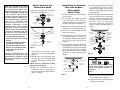
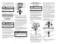
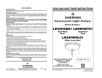
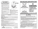
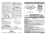
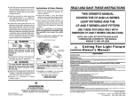
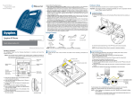
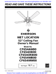
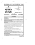
LIMITED WARRANTY
What The Warranty Covers:
All products covered by this Owner’s Manual are warranted against all defects in workmanship and materials. You must be the
original purchaser or user of the product to be covered.
READ AND SAVE THESE INSTRUCTIONS
What The Period Of Coverage Is:
The fluorescent bulb and electronic ballast are covered by this warranty for two years after the date of purchase; all other
components are covered for one year after the date of purchase. ANY IMPLIED WARRANTY OF MERCHANTABILITY OR
FITNESS FOR A PARTICULAR PURPOSE, MADE WITH RESPECT TO COMPONENTS AND ACCESSORIES IS ALSO LIMITED TO
ONE YEAR.
What Will Emerson Electric Co. Do To Correct Problems:
Emerson Electric Co. will replace a defective Emerson Light Fixture at no charge to you. WE WILL SHIP THE REPAIRED
PRODUCT OR REPLACEMENT TO YOU AT NO CHARGE, BUT YOU ARE RESPONSIBLE FOR ALL COSTS OF REMOVAL,
REINSTALLATION AND SHIPPING OF THE PRODUCT TO EMERSON.
How Can You Get Service:
YOU MUST HAVE PROOF OF YOUR PURCHASE OF THE LIGHT FIXTURE TO OBTAIN LIMITED WARRANTY SERVICE. KEEP
YOUR RECEIPT OR OTHER PROOF OF PURCHASE. You can return the product to our factory or to your nearest authorized
service center.
• To return the product to the factory, obtain a return authorization and service identification tag by writing to Air Comfort
Products, Division of Emerson Electric Co., 8100 W. Florissant Ave., St. Louis, MO 63136. Include all model numbers
shown on the product with your request.
• To return the product to an authorized service center, call 1-800-654-3545 for the address of the nearest authorized service
center.
You will be responsible for all insurance, freight or other transportation charges to our factory or authorized service center.
Your Emerson Light Fixture should be properly packed to avoid damage in transit since we will not be responsible for any such
damage.
What Is Not Covered:
This warranty also does not cover any defects, malfunctions or failures caused by:
• Repairs by persons not authorized by Emerson Electric Co.,
• Use of parts or accessories not authorized by Emerson Electric Co.,
• Mishandling, improper installation, modifications or damage to your light fixture while in your possession, or
• Unreasonable use, misuse, abuse, including failing to do reasonable and necessary maintenance, and normal wear and tear.
Additionally, this warranty and any implied warranty of merchantability or fitness for a particular purpose are voided when:
• The original purchaser or user ceases to own the product, or
• The ceiling fan is moved from its original point of installation.
This warranty is only valid within the 50 states of the United States and the District of Columbia. No other written or oral
warranties apply, and no employee, agent, dealer or other person is authorized to give any warranties on behalf of Emerson
Electric Co.
REPAIR, REPLACEMENT OR A REFUND ARE THE EXCLUSIVE REMEDIES AVAILABLE UNDER THIS WARRANTY AND
EMERSON IS NOT RESPONSIBLE FOR DAMAGES OF ANY KIND, INCLUDING INCIDENTAL AND CONSEQUENTIAL DAMAGES.
Incidental damages include but are not limited to such damages as loss of time and loss of use. Consequential damages
include but are not limited to the cost of repairing or replacing other property which was damaged if this product does not
work properly.
Fluorescent Light Fixture
Model Numbers
LK59FOM
LK59FSST
Opal Matte
Bowl
Sandstone
Bowl
LK59FWHL
White Linen Bowl
How State Law Relates To The Warranty:
Some states do not allow the exclusion or limitation of incidental or consequential damages so the above exclusion or
limitation may not apply to you. This warranty gives you specific legal rights, and you may also have other rights which vary
from state to state.
For repair parts, phone:
USE THIS FIXTURE ONLY WITH
EMERSON “CF” SERIES
CEILING FANS
1-800-654-3545
Net Weight:
4.0
Lbs.
FOUR 13-WATT GU24
FLUORESCENT BULBS INCLUDED
Form No. BP7364
Part No. F40BP73640000
Air Comfort Products
DIVISION OF EMERSON ELECTRIC CO.
8100 W. Florissant ¥ St. Louis, MO 63136
ENERGY STAR
Printed in China
01/08
Part No. F40BP73640000
Form No. BP7364
U.L. Model No.: LK59F
!
How To Order Repair Parts
WARNING
Safety Instructions
When ordering repair parts, always give the following information:
To avoid fire, shock, and serious personal injury, follow all instructions
carefully.
1. Read your Owner's Manual carefully before installing the light fixture.
Retain Owner's Manual for future reference.
2. Be careful of the fan and blades when cleaning, painting, or working near
the fan. Before installing or servicing the light fixture or ceiling fan, switch
power off at service panel and lock service panel disconnecting means to
prevent power from being switched on accidentally. When the service
disconnecting means cannot be locked, securely fasten a warning device,
such as a tag, to the service panel.
3. Do not exceed the wattage indicated on fixture.
-
Name of Item
-
Part Description
-
Model Number
The model number will be found on a label attached to the light kit fitter. For repair
parts, phone: 1-800-654-3545.
Notes
ADDITIONAL SAFETY INSTRUCTIONS FOR INSTALLATION
1. To avoid possible electrical shock be sure electricity is turned off at the
main fuse or circuit breaker box before wiring.
2. Make certain no bare wires are exposed outside the wire connectors.
3. All wiring must conform to national and local electrical codes.
4. Follow the recommended instructions for the proper method of wiring your
new light fixture. If you feel you do not have enough electrical wiring
knowledge or experience, have your light fixture installed by a licensed
electrician. Any electrical work not described in this manual should be
performed by a licensed electrician.
To reduce the risk of possible fire and electrical shock, install only on
Emerson “CF” Series Ceiling Fans. This light kit is not to be used with CF652,
CF653, CF654, CF670, CF680, CF690, CF695, CF742, CF800 and CF2000 Model
Ceiling Fans installed in damp or wet locations.
Assembly and Installation
!
WARNING
!
Do not install or use the light fixture
if any part is missing or damaged.
Call toll-free:
WARNING
To avoid possible electrical shock,
be sure electricity is turned off at the
main fuse or circuit breaker box
before wiring.
1-800-654-3545
NOTE: The GU24 fluorescent bulbs for this light fixture are not dimmable.
Wall controls and remote controls with a light dimming function should not be
used in conjunction with this light kit.
2
7
Replacement of the
Fluorescent Bulbs
NOTE: This equipment has been
tested and found to comply with
part 18 of the FCC Rules. This
equipment generates, uses and can
radiate radio frequency energy and
if not installed and used in
accordance with the instructions,
may cause harmful interference to
radio communications. However,
there is no guarantee that
interference will not occur in a
particular installation. If this
equipment does cause harmful
interference to radio or television
reception, which can be determined
by turning the equipment OFF and
ON, the user is encouraged to
correct the interference by one or
more of the following measures:
1. Remove the pendants from the fan and
light switch chains (Figure 7).
LIGHT FITTER
13-WATT GU24
FLUORESCENT BULB
Installation on Emerson
Fans with Modular
(Detachable)
Switch Cups
7. Insert the black and white wires through
the lockwasher(8) and hex nut(9)
supplied. Firmly tighten the hex nut to
secure the light kit fitter(7) to the switch
cup(1) (Figure 2).
1. Remove all parts and parts packages
from the carton.
8. Connect the white wire from the switch
cup to the white wire of the light fitter
(Figure 2). Connect the blue wire from
the switch cup to the black wire of the
light fitter. Use U.L. listed wire
connectors (previously removed in
Step 5) to make connections (Figures 2
and 3).
2. On the ceiling fan, remove the switch
cup(1) from the cover plate(2) by
removing the three screws(3) around
the side of the switch cup (Figure 1).
THREADED
NIPPLE
3. Disconnect the motor connector(4) from
the switch cup connector(5) (Figure 1).
LIGHT FITTER CHAIN
(1) GLASS
SHADE
FAN SWITCH CHAIN
(4) GUIDE PLATE
HEX NUT
- Reorient or relocate the receiving
antenna.
(3) GLASS CAP
- Increase the separation between
the equipment and receiver.
(2) FINIAL NUT
FAN SWITCH
PENDANT
LIGHT SWITCH
PENDANT/COUPLING
- Connect the equipment into an
outlet on a circuit different from
that to which the receiver is
connected.
Figure 7
2. Hold the glass shade(1) securely while
removing the finial nut(2), glass
cap(3), hex nut and the guide plate(4)
(Figure 7).
Changes or modifications not
expressly approved by the party
responsible for compliance could
void the user’s authority to operate
the equipment.
3. Carefully place the glass shade, finial
nut, glass cap, hex nut and guide plate
in a safe place while replacing the
bulb(s).
4. Remove the center screw(6) from the
switch cup (Figure 1).
(2) COVER PLATE
(5) SWITCH CUP
CONNECTOR
(4) MOTOR
CONNECTOR
5. Carefully locate the white and blue
wires (labeled either "L" or "LIGHT") in
the switch cup. Remove and retain the
wire connectors(6) from the wires
(Figure 2).
(6) WIRE
CONNECTORS
BLUE WIRE
BLACK WIRE
(3) SCREWS
(9) HEX NUT
WHITE WIRES
FAN SWITCH
CHAIN
(8) LOCKWASHER
(1) SWITCH
CUP
6. Insert the black and white wires from
the light fitter(7) through the center hole
in the switch cup (Figure 2) and thread
the switch cup tightly onto the light
fitter. Hold wires taut while installing
switch cup to prevent the wires from
twisting.
(7) LIGHT FITTER
Figure 2
!
(4) MOTOR
CONNECTOR
NOTE: Use only replacement 13-watt
GU24 fluorescent bulb(s).
(3) SCREWS
4. Install the replacement bulb in
accordance with the “Installation of
Fluorescent Bulbs and Glass Shade”
section, on Page 5.
(1) SWITCH
CUP
(6) CENTER SCREW
WARNING
(2) COVER PLATE
(5) SWITCH CUP
CONNECTOR
To avoid possible fire or electrical
shock, make certain no bare wire
strands are exposed outside wire
connectors.
Figure 3
Figure 1
9. Carefully tuck all wires and splices
into the switch cup(1). (Figure 2.)
10. Connect the motor connector(4) to the
switch cup connector(5).
6
3
11. Position the cup/light fitter(1)(7) on
the cover plate(2) and install the
three screws(3) that were previously
removed in Step 2 and tighten
securely.
FAN SWITCH
CHAIN
(1) SWITCH
HOUSING
ASSEMBLY
(3) WIRE
CONNECTORS
BLUE WIRE
WHITE WIRES
(7) HEX NUT
(8) LOCKWASHER
BLACK WIRE
!
WARNING
(5) COVER
(4) CENTER
SCREW
To avoid possible fire or electric shock,
be careful not to pinch wires between
switch cup and the cover plate.
(2) SCREWS
(6) LIGHT FITTER
12. Proceed to “Installation of
Fluorescent Bulbs and Glass Shade”
section.
Figure 4
5. Carefully locate the white and blue
wires (labeled either “L” or “LIGHT”) in
the switch housing. Remove and retain
the wire connectors(3) from the wires.
Installation on Emerson
Fans Having Two-Piece
Die-Cast Switch
Housings
6. Connect the white wire from the ceiling
fan to the white wire of the light fitter(6).
Connect the blue wire from the ceiling
fan to the black wire of the light fitter.
Use U.L. listed wire connectors(3)
(previously removed in Step 5) to make
connections. (Figures 3 and 4.)
1. Remove all parts and parts packages
from carton.
!
WARNING
To avoid possible electric shock, be sure
electricity is turned off at the main fuse
or circuit breaker box before wiring.
Installation of
Fluorescent Bulbs and
Glass Shade
!
5. Slide the guide plate(5) up the light
fitter’s threaded nipple until the glass
shade(1) mates with the bottom of the
light fitter plate (Figure 6).
6. Install the hex nut onto the threaded
nipple and firmly hand tighten the nut to
secure the guide plate(5) and glass
shade(1) onto the light fitter(2).
7. Slide the fan switch chain(3) through
the side hole of the glass cap and slide
the light fitter chain(4) through the
center hole of the glass cap(6). Slide
the glass cap(6) up the threaded nipple
until it rests against the bottom of the
glass shade(1) (Figure 6).
8. Pass the light fitter chain(4) through the
center of the finial nut and fasten the
finial nut(7) onto the fitter nipple. Gently
hand tighten the finial nut(7) up against
the bottom of the glass cap(6) to secure
it in position (Figure 6).
9. Reinstall the fan switch pendant(8) to
the fan switch chain(3) (Figure 6).
WARNING
To avoid fire hazard, do not exceed
wattage indicated on the fixture.
1. Carefully position one of the GU24
fluorescent bulbs(1) (supplied) into the
light fitter socket. Twist the bulb
clockwise, approximately 1/16 turn, to
engage the bulbs pins into the light
fitter socket holes(2) (Figure 5). Install
the remaining three GU24 fluorescent
bulbs in the same manner.
2. Remove the fan switch pendant(3) from
the fan switch chain(4) for installation of
glass. Place the fan switch chain
through the light fitter plate(5) hole
(Figure 5).
(1) 13-WATT GU24
FLUORESCENT BULB (4)
13-WATT GU24
FLUORESCENT BULB
(2) LIGHT FITTER
(2) LIGHT FITTER
SOCKET
7. Carefully tuck all wires and splices into
the switch housing(1).
2. Remove the cover(5) from the fan
switch housing(1) by removing the two
outer screws(2). (See Figure 4).
8. Attach the cover/light fitter(5)(6) to the
switch assembly housing(1) using the
two outer screws(2) that were removed
in Step 2) (Figure 4.)
3. Remove the center screw(4) from the
cover(5). Insert the black and white
wires from the light fitter(6) thru the
hole and thread the switch housing
cover tightly onto the light fitter.
!
WARNING
To avoid fire or electrical shock, be
careful not to pinch wires between
the switch housing assembly and
the cover.
4. Insert the black and white wires through
the lockwasher(8) and hex nut(7)
supplied. Firmly tighten the hex nut to
secure the light fitter to the switch
housing cover(5).
9. Proceed to “Installation of Fluorescent
Bulbs and Glass Shade” section.
4
THREADED
NIPPLE
(5) LIGHT FITTER
PLATE HOLES
Figure 5
LIGHT FITTER
PLATE
(4) FAN SWITCH
CHAIN
(4) LIGHT FITTER
CHAIN
(5) GUIDE PLATE
HEX NUT
(3) FAN SWITCH
PENDANT
LIGHT FITTER
PLATE
(1) GLASS
SHADE
(3) FAN SWITCH
CHAIN
(6) GLASS CAP
3. Place glass shade (1) onto light fitter(2)
making sure that both fan switch
chain(3) and light fitter chain(4) are
positioned through the center hole in
glass shade(1) (Figure 6).
4. Slide the switch chain(3) through the
side hole of the guide plate(5) and the
light fitter chain(4) through the center
hole of the guide plate(5) (Figure 6).
(7) FINIAL NUT
(8) FAN SWITCH
PENDANT
(9) LIGHT SWITCH
PENDANT/COUPLING
Figure 6
10. Installation is now complete. Turn on
the electricity at the main fuse or
circuit breaker box.
5