1
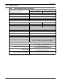
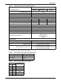
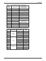
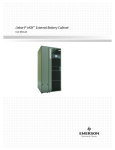
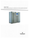
AC Power
For Business-Critical Continuity™
Liebert® NX™ Battery System
Installation Manual–225-600kVA
BATTERY CABINET PRECAUTIONS
The following warning applies to all battery cabinets supplied with UPS systems. Additional
warnings and cautions applicable to battery cabinets may be found in Important Safety
Instructions beginning on page 1.
! WARNING
Internal battery strapping must be verified prior to moving a battery cabinet (after initial
installation).
• Battery cabinets contain non-spillable batteries.
• Keep units upright.
• Do not stack.
• Do not tilt.
Failure to heed this warning could result in smoke, fire or electric hazard.
Call 1-800-LIEBERT prior to moving battery cabinets (after initial installation).
CONTACTING LIEBERT FOR SUPPORT
To contact Emerson Network Power Liebert Services for information or repair service in the United
States, call 1-800-LIEBERT (1-800-543-2378). Liebert Services offers a complete range of startup
services, repair services, preventive maintenance plans and service contracts.
For repair or maintenance service outside the 48 contiguous United States, contact Liebert Services,
if available in your area.
For Liebert Services to assist you promptly, have the following information available:
Part Numbers:
Serial Numbers:
Rating:
Date Purchased:
Date Installed:
Location:
Battery Voltage:
Battery Reserve Time:
Product Warranty Registration
To register for warranty protection, visit the Service and Support section of our Web site at:
www.liebert.com
Click on Product Registration and fill out the form.
TABLE OF CONTENTS
IMPORTANT SAFETY INSTRUCTIONS . . . . . . . . . . . . . . . . . . . . . . . . . . . . . . . . . . . . . . . . . . . . . . . .1
SAVE THESE INSTRUCTIONS . . . . . . . . . . . . . . . . . . . . . . . . . . . . . . . . . . . . . . . . . . . . . . . . .1
1.0
MECHANICAL INSTALLATION . . . . . . . . . . . . . . . . . . . . . . . . . . . . . . . . . . . . . . . . . . . . . . . .3
1.1
Introduction . . . . . . . . . . . . . . . . . . . . . . . . . . . . . . . . . . . . . . . . . . . . . . . . . . . . . . . . . . . . . . . . 3
1.2
Preliminary Checks . . . . . . . . . . . . . . . . . . . . . . . . . . . . . . . . . . . . . . . . . . . . . . . . . . . . . . . . . . 3
1.3
Environmental Considerations . . . . . . . . . . . . . . . . . . . . . . . . . . . . . . . . . . . . . . . . . . . . . . . . . 3
1.3.1
1.3.2
1.4
Battery Room . . . . . . . . . . . . . . . . . . . . . . . . . . . . . . . . . . . . . . . . . . . . . . . . . . . . . . . . . . . . . . . . 3
Storage . . . . . . . . . . . . . . . . . . . . . . . . . . . . . . . . . . . . . . . . . . . . . . . . . . . . . . . . . . . . . . . . . . . . . 3
Positioning . . . . . . . . . . . . . . . . . . . . . . . . . . . . . . . . . . . . . . . . . . . . . . . . . . . . . . . . . . . . . . . . . 4
1.4.1
1.4.2
1.4.3
Moving the Cabinets. . . . . . . . . . . . . . . . . . . . . . . . . . . . . . . . . . . . . . . . . . . . . . . . . . . . . . . . . . . 4
Clearances. . . . . . . . . . . . . . . . . . . . . . . . . . . . . . . . . . . . . . . . . . . . . . . . . . . . . . . . . . . . . . . . . . . 5
Raised Floor Mounting . . . . . . . . . . . . . . . . . . . . . . . . . . . . . . . . . . . . . . . . . . . . . . . . . . . . . . . . . 5
1.5
System Composition . . . . . . . . . . . . . . . . . . . . . . . . . . . . . . . . . . . . . . . . . . . . . . . . . . . . . . . . . . 5
2.0
BATTERY INSTALLATION . . . . . . . . . . . . . . . . . . . . . . . . . . . . . . . . . . . . . . . . . . . . . . . . . . .6
2.1
Safety . . . . . . . . . . . . . . . . . . . . . . . . . . . . . . . . . . . . . . . . . . . . . . . . . . . . . . . . . . . . . . . . . . . . . 6
2.2
Layout . . . . . . . . . . . . . . . . . . . . . . . . . . . . . . . . . . . . . . . . . . . . . . . . . . . . . . . . . . . . . . . . . . . . . 6
2.3
Cable Entry. . . . . . . . . . . . . . . . . . . . . . . . . . . . . . . . . . . . . . . . . . . . . . . . . . . . . . . . . . . . . . . . . 8
2.4
Power Connection . . . . . . . . . . . . . . . . . . . . . . . . . . . . . . . . . . . . . . . . . . . . . . . . . . . . . . . . . . . . 8
2.4.1
2.4.2
2.4.3
2.4.4
Connected System . . . . . . . . . . . . . . . . . . . . . . . . . . . . . . . . . . . . . . . . . . . . . . . . . . . . . . . . . . . .
Stand-Alone System . . . . . . . . . . . . . . . . . . . . . . . . . . . . . . . . . . . . . . . . . . . . . . . . . . . . . . . . . .
Attached/Detached System . . . . . . . . . . . . . . . . . . . . . . . . . . . . . . . . . . . . . . . . . . . . . . . . . . . . .
Grounding . . . . . . . . . . . . . . . . . . . . . . . . . . . . . . . . . . . . . . . . . . . . . . . . . . . . . . . . . . . . . . . . . . .
8
8
8
9
2.5
Control Connection. . . . . . . . . . . . . . . . . . . . . . . . . . . . . . . . . . . . . . . . . . . . . . . . . . . . . . . . . . . 9
2.6
Alber Monitoring System—Optional . . . . . . . . . . . . . . . . . . . . . . . . . . . . . . . . . . . . . . . . . . . . 10
2.7
External Battery Room Temperature Sensor—Optional . . . . . . . . . . . . . . . . . . . . . . . . . . . . 10
3.0
INSTALLATION DRAWINGS . . . . . . . . . . . . . . . . . . . . . . . . . . . . . . . . . . . . . . . . . . . . . . . . . 11
4.0
SPECIFICATIONS . . . . . . . . . . . . . . . . . . . . . . . . . . . . . . . . . . . . . . . . . . . . . . . . . . . . . . . .28
i
FIGURES
Figure 1
Figure 2
Figure 3
Figure 4
Figure 5
Figure 6
Figure 7
Figure 8
Figure 9
Figure 10
Figure 11
Figure 12
Figure 13
Figure 14
Figure 15
Figure 16
Figure 17
Figure 18
Figure 19
Figure 20
Figure 21
Figure 22
Figure 23
Figure 24
Shipping bolts—Top-Terminal Battery Cabinet . . . . . . . . . . . . . . . . . . . . . . . . . . . . . . . . . . . . . . . . 4
Battery cabinets connected, attached to UPS . . . . . . . . . . . . . . . . . . . . . . . . . . . . . . . . . . . . . . . . . . 7
Battery cabinets connected, detached from UPS . . . . . . . . . . . . . . . . . . . . . . . . . . . . . . . . . . . . . . . 7
Stand-alone battery cabinets, detached from UPS . . . . . . . . . . . . . . . . . . . . . . . . . . . . . . . . . . . . . . 8
Control cable layout—Liebert NX UPS to Liebert NX Battery Cabinet . . . . . . . . . . . . . . . . . . . . . 9
Battery temperature sensor control connection . . . . . . . . . . . . . . . . . . . . . . . . . . . . . . . . . . . . . . . 10
Outline drawing, Liebert Top-Terminal Battery Cabinet . . . . . . . . . . . . . . . . . . . . . . . . . . . . . . . 11
Main components, Liebert Top-Terminal Battery Cabinet . . . . . . . . . . . . . . . . . . . . . . . . . . . . . . 12
Terminal details, Liebert Top-Terminal Battery Cabinet . . . . . . . . . . . . . . . . . . . . . . . . . . . . . . . 13
Front Terminal Battery Cabinet shipping split . . . . . . . . . . . . . . . . . . . . . . . . . . . . . . . . . . . . . . . 14
Front Terminal Battery Cabinet outline drawing. . . . . . . . . . . . . . . . . . . . . . . . . . . . . . . . . . . . . . 15
Front Terminal Battery Cabinet main components, layout . . . . . . . . . . . . . . . . . . . . . . . . . . . . . . 16
Front Terminal detail drawing. . . . . . . . . . . . . . . . . . . . . . . . . . . . . . . . . . . . . . . . . . . . . . . . . . . . . 17
Liebert NX Stand-Alone Junction Cabinet terminal wiring . . . . . . . . . . . . . . . . . . . . . . . . . . . . . 18
Liebert NX Attached Junction Cabinet—terminal detail and outline drawing . . . . . . . . . . . . . . 19
Liebert NX Battery Cabinet control wiring . . . . . . . . . . . . . . . . . . . . . . . . . . . . . . . . . . . . . . . . . . . 20
Attached battery cabinet connections . . . . . . . . . . . . . . . . . . . . . . . . . . . . . . . . . . . . . . . . . . . . . . . 21
Ground strap location for connected cabinets . . . . . . . . . . . . . . . . . . . . . . . . . . . . . . . . . . . . . . . . . 21
Typical Alber battery monitoring connections . . . . . . . . . . . . . . . . . . . . . . . . . . . . . . . . . . . . . . . . 22
Alber battery monitoring wiring to multiple battery cabinets . . . . . . . . . . . . . . . . . . . . . . . . . . . . 23
Alber battery monitoring assembly diagram. . . . . . . . . . . . . . . . . . . . . . . . . . . . . . . . . . . . . . . . . . 24
Top-Terminal battery configuration . . . . . . . . . . . . . . . . . . . . . . . . . . . . . . . . . . . . . . . . . . . . . . . . 25
Front-Terminal battery configuration . . . . . . . . . . . . . . . . . . . . . . . . . . . . . . . . . . . . . . . . . . . . . . . 26
Busbar connection between Battery Cabinet and Attached Junction Cabinet . . . . . . . . . . . . . . . 27
TABLES
Table 1
Table 2
Table 3
Table 4
Table 5
Table 6
Table 7
Table 8
Table 9
Table 10
Alber battery monitoring assembly connections . . . . . . . . . . . . . . . . . . . . . . . . . . . . . . . . . . . . . . .
Liebert NX Battery Cabinet specifications . . . . . . . . . . . . . . . . . . . . . . . . . . . . . . . . . . . . . . . . . . .
Liebert NX Junction Cabinet specifications . . . . . . . . . . . . . . . . . . . . . . . . . . . . . . . . . . . . . . . . . .
Alber battery monitoring option specifications . . . . . . . . . . . . . . . . . . . . . . . . . . . . . . . . . . . . . . . .
DC currents for Liebert NX modules . . . . . . . . . . . . . . . . . . . . . . . . . . . . . . . . . . . . . . . . . . . . . . . .
Liebert NX Battery Cabinet internal breaker. . . . . . . . . . . . . . . . . . . . . . . . . . . . . . . . . . . . . . . . .
Liebert NX Battery Cabinet approximate weights . . . . . . . . . . . . . . . . . . . . . . . . . . . . . . . . . . . . .
Recommended conduit and cable sizes from Liebert NX UPS to DC supply. . . . . . . . . . . . . . . . .
Battery torque values . . . . . . . . . . . . . . . . . . . . . . . . . . . . . . . . . . . . . . . . . . . . . . . . . . . . . . . . . . . .
Torque specifications, unless otherwise labeled . . . . . . . . . . . . . . . . . . . . . . . . . . . . . . . . . . . . . . .
ii
24
28
29
29
29
30
30
31
31
32
IMPORTANT SAFETY INSTRUCTIONS
SAVE THESE INSTRUCTIONS
This manual contains important instructions that should be followed during installation of your
Liebert NX Battery Cabinet and accessories. Read this manual thoroughly, paying special attention
to the sections that apply to your installation, before working with the battery system. Retain this
manual for use by installing personnel.
! WARNING
Risk of electrical shock. Can cause personal injury and death.
Special safety precautions are required for procedures involving handling, installation and
maintenance of the UPS system. Only properly trained and qualified personnel wearing
appropriate personal protective equipment should be involved in installing the Liebert NX
Battery system or preparing the system for installation.
Special care must be taken when working with the batteries associated with this equipment.
When connected together, the battery terminal voltage will exceed 400VDC and is potentially
lethal. Be constantly aware that the battery system contains high DC as well as AC voltages.
Check for voltage with AC and DC voltmeters before making contact.
Observe all DC safety precautions before working on or near the DC system.
Follow all battery safety precautions when installing, charging or servicing batteries. In
addition to the hazard of electric shock, gas produced by batteries can be explosive and
sulfuric acid can cause severe burns.
The following precautions must be observed when working on batteries:
•
•
•
•
•
•
Remove watches, rings and other metal objects.
Use tools with insulated handles.
Wear rubber gloves and boots.
Do not lay tools or metal parts on top of batteries.
Disconnect charging source prior to connecting or disconnecting battery terminals.
Determine whether the battery is grounded. If it is grounded, remove source of ground.
Contact with any part of a grounded battery can result in electrical shock. The likelihood of
such shock will be reduced if such grounds are removed during installation and
maintenance.
If a battery leaks electrolyte, or is otherwise physically damaged, it must be replaced, stored
in a container resistant to sulfuric acid and disposed of in accordance with local regulations.
If electrolyte comes into contact with the skin, the affected area should be washed
immediately with water.
! WARNING
Risk of electric shock, explosive reaction, hazardous chemicals and fire. Can cause equipment
damage, personal injury and death.
Lead-acid batteries contain hazardous materials. Batteries must be handled, transported and
recycled or discarded in accordance with federal, state and local regulations. Because lead is a
toxic substance, lead-acid batteries must be recycled rather than discarded.
Do not dispose of a battery in a fire. The battery may explode.
Do not open or mutilate the battery or batteries. Released electrolyte is harmful to the skin
and eyes. It is toxic.
! WARNING
Risk of electric shock. Can cause personal injury and death.
In case of fire involving electrical equipment, use only carbon dioxide fire extinguishers or
those approved for use in fighting electrical fires.
1
Liebert® NX™
! WARNING
Risk of heavy unit falling over. Can cause equipment damage, injury and death.
Exercise extreme care when handling battery cabinets to avoid equipment damage or injury
to personnel. The battery system cabinets weigh from 3760 to 8990 lb. (1706 to 4078kg).
Locate center of gravity symbols
and determine unit weight before handling each
cabinet. Test lift and balance the cabinets before transporting. Maintain minimum tilt from
vertical at all times.
Slots at the base of the cabinets are intended for forklift use. Base slots will support the unit
only if the forks are completely beneath the unit.
! WARNING
Risk of electric shock. Can cause equipment damage, personal injury and death.
The area around the battery system must be kept free of puddles of water, excess moisture
and debris.
Observe all precautions in the Operation and Maintenance Manual, SL 25425, before as well
as during all installation and maintenance procedures. Observe all battery safety precautions
before working on or near the battery.
This equipment contains several circuits that are energized with high voltage. Only test
equipment designed for troubleshooting should be used. This is particularly true for
oscilloscopes. Always check with an AC and DC voltmeter to ensure safety before making
contact or using tools. Even when the power is turned Off, dangerously high potential electric
charges may exist at the capacitor banks and at the batteries.
All power and control wiring must be installed by a properly trained and qualified electrician.
All power and control wiring must comply with the NEC and applicable local codes.
When performing maintenance with any part of the equipment under power, service
personnel and test equipment must be standing on rubber mats. The service personnel must
wear insulating shoes for isolation from direct contact with the floor (earth ground).
One person should never work alone, even if all power is disconnected from the equipment. A
second person should be standing by to assist and to summon help in case of an accident.
NOTE
Materials sold hereunder cannot be used in the patient vicinity (e.g., use where UL, cUL or IEC
60601-1 is required). Medical applications such as invasive procedures and electrical life
support equipment are subject to additional terms and conditions.
NOTICE
This unit complies with the limits for a Class A digital device, pursuant to Part 15 Subpart J
of the FCC rules. These limits provide reasonable protection against harmful interference in a
commercial environment. This unit generates, uses and radiates radio frequency energy and,
if not installed and used in accordance with this instruction manual, may cause harmful
interference to radio communications. Operation of this unit in a residential area may cause
harmful interference that the user must correct at his own expense.
Liebert® NX™
2
Mechanical Installation
1.0
MECHANICAL INSTALLATION
1.1
Introduction
This following section describes the requirements that must be taken into account when planning the
positioning and cabling of the Liebert NX battery equipment.
This chapter is a guide to general procedures and practices that should be observed by the installing
engineer. The particular conditions of each site will determine the applicability of such procedures.
NOTICE
Do not apply electrical power to the UPS equipment before the arrival of the commissioning
engineer.
1.2
Preliminary Checks
Before installing the battery equipment, please carry out the following preliminary checks:
• Visually examine the equipment for transit damage, both internally and externally. Report any
damage to the shipper immediately.
• Verify that the correct equipment is being installed. The equipment supplied has an identification
tag inside the main door.
• Verify that the battery room satisfies the environmental conditions stipulated in the equipment
specification, paying particular attention to the ambient temperature and air exchange system.
1.3
Environmental Considerations
1.3.1
Battery Room
Batteries should be mounted in an environment where the temperature is consistent and even over
the whole battery. Temperature is a major factor in determining the battery life and capacity. Typical
battery manufacturer performance data are quoted for an operating temperature between 68 and
77°F (20 and 25°C). Operating above this range will reduce the battery life while operation below this
range will reduce the battery capacity.
Battery Temperature
In a normal installation, the battery temperature should be kept between 59 and 77°F (15°C and
25°C).
NOTE
Keep batteries away from main heat sources, main air inlets, etc.
1.3.2
Storage
Should the equipment not be installed immediately, it must be stored in a room for protection against
excessive humidity and heat sources (see Table 2).
NOTICE
Risk of deep discharge. Can cause permanent damage to batteries.
An unused battery must be recharged periodically as recommended by the battery
manufacturer.
3
Liebert® NX™
Mechanical Installation
1.4
Positioning
The cabinet is structurally designed to handle lifting from the base.
Power terminals, auxiliary terminals blocks and power switches are accessed from the front and top.
Removable panels on the top are secured to the chassis by screws. The door can be opened to give
access to the power connections bars, auxiliary terminal blocks and power isolators. The front door
can be opened 180° for easier service and more flexibility in installation.
1.4.1
Moving the Cabinets
The route to be travelled between the point of arrival and the unit’s installation location must be
planned to make sure that all passages are wide enough for the unit and that floors are capable of
supporting its weight (for instance, check that doorways, lifts, ramps, etc., are adequate and that
there are no impassable corners or changes in the level of corridors).
Ensure that the cabinet weight is within the designated surface weight loading (kg/cm2) of any
handling equipment. See Table 2 for weight details.
Ensure that any lifting equipment used to move the battery equipment has sufficient lifting capacity.
Battery system equipment can be handled by a forklift or similar equipment.
Because the weight distribution in the cabinet is not symmetrical, use extreme care during handling
and transporting.
When moving the unit by forklift, care must be taken to protect the panels. Do not exceed a 15° tilt
with the forklift. Bottom structure will support the unit only if the forks are completely beneath the
unit.
Handling the unit with straps is not authorized.
! WARNING
Risk of heavy unit falling over. Can cause equipment damage, injury and death.
Exercise extreme care when handling battery cabinets. The battery system cabinets weigh
from 3760 to 8990 lb. (1706 to 4078kg).
Locate center of gravity symbols
and determine unit weight before handling each
cabinet. Test lift and balance the cabinets before transporting. Maintain minimum tilt from
vertical at all times.
Slots at the base of the cabinets are intended for forklift use. Base slots will support the unit
only if the forks are completely beneath the unit.
The cabinet with top terminal batteries ships with extra bolts installed on the interior doors. Once the
cabinet is in the final position, these bolts can be removed. See Figure 1
Figure 1
Shipping bolts—Top-Terminal Battery Cabinet
Shipping
Bolts
Shipping
Bolts
Shipping
Bolts
* Outer doors removed
for clarity
Shipping
Bolts
Shipping
Bolts
Shipping
Bolts
Shipping
Shipping Bolts Bolts
Liebert® NX™
4
Mechanical Installation
1.4.2
Clearances
Liebert NX has no ventilation grilles at either side or at the rear of the battery system equipment.
Clearance around the front of the equipment should be sufficient to enable free passage of personnel
with the doors fully opened. It is important to leave a distance of 24" (610mm) between the top of the
cabinet and the ceiling of the room in which it is installed to permit adequate circulation of air coming
out of the unit and for service access.
1.4.3
Raised Floor Mounting
If the equipment is to be placed on a raised floor, it should be mounted on a pedestal suitably designed
to accept the equipment point loading. Refer to the base view to design this pedestal.
1.5
System Composition
A battery system can consist of a number of equipment cabinets, depending on the individual system
design requirements, e.g., Battery Cabinet, Junction Cabinet. Refer to 3.0 - Installation Drawings
for the positioning of the cabinets described below.
5
Liebert® NX™
Battery Installation
2.0
BATTERY INSTALLATION
2.1
Safety
Special care should be taken when working with the batteries associated with the Liebert NX Battery
System equipment. When all the cells are connected together, the battery terminal voltage will exceed
400V and is potentially lethal. A primary safety consideration is to install the battery equipment in
an isolated area, accessible only to properly trained and qualified maintenance personnel.
! WARNING
Risk of electric shock. Can cause equipment damage, personal injury and death.
Hazardous battery voltage present behind covers. No user-serviceable parts are located
behind covers that require a tool for removal. Only properly trained and qualified service
personnel are authorized to remove such covers or perform installation or maintenance.
The following general battery safety precautions and warnings must be observed at all times:
• A battery can present risk of electric shock or burn from high short circuit currents.
• When connected in a string, the voltage will exceed 400VDC. This voltage is potentially
lethal. Always observe high-voltage precautions.
• Eye protection must be worn to prevent injury from accidental electrical arcs.
• Remove rings, watches, necklaces, bracelets and all other metal objects.
• Use only tools with insulated handles.
• Wear appropriate personal protective equipment when handling batteries.
• If a battery leaks electrolyte or is otherwise physically damaged, it should be placed in a
container resistant to wire and disposed of in accordance with local regulations.
• If electrolyte comes into contact with the skin, the affected area should be washed
immediately with plenty of clean water.
• Batteries must always be disposed of according to local environmental laws.
• When replacing batteries, use the same number and type that were originally fitted.
• Disconnect charging source prior to connecting or disconnecting battery terminals.
• Determine if the battery is grounded. If it is grounded, remove source of ground. Contact
with any part of a grounded battery can result in electrical shock.
• Battery support tray must be used whenever a battery tray is being pulled out.
2.2
Layout
Depending on the site layout, the battery cabinets can be installed in any of several ways:
•
•
•
•
Connected—Multiple battery cabinets bolted together
Stand-Alone—Cabinet not bolted to Liebert NX equipment
Attached—Battery cabinets are bolted to a Liebert NX UPS
Detached—Battery cabinets are not bolted to a Liebert NX UPS
See Figures 2 through 4.
Liebert® NX™
6
Battery Installation
Figure 2
Battery cabinets connected, attached to UPS
Note: Remove knockout
in the UPS low-voltage
section to route control
cables between the
battery cabinet and UPS.
Figure 3
Additional
Liebert
NX
Battery
Cabinet
Liebert
NX
Battery
Cabinet
Liebert
NX
UPS
Battery cabinets connected, detached from UPS
Liebert
NX
UPS
Attached
Junction
Cabinet
Liebert
NX
Battery
Cabinet
Additional
Liebert
NX
Battery
Cabinet
The junction cabinet allows for
sufficient conduit landing space.
It is required for systems of
500kVA or above.
Additional
Liebert
NX
Battery
Cabinet
Liebert
NX
Battery
Cabinet
7
Attached
Junction
Cabinet
Liebert
NX
UPS
Liebert® NX™
Battery Installation
Figure 4
Stand-alone battery cabinets, detached from UPS
Liebert
NX
UPS
StandAlone
Junction
Cabinet
Liebert
NX
Battery
Cabinet
Additional
Liebert
NX
Battery
Cabinet
The junction cabinet
provides sufficient
conduit landing space
and is required for all
systems in this
configuration.
Additional
Liebert
NX
Battery
Cabinet
2.3
Liebert
NX
Battery
Cabinet
StandAlone
Junction
Cabinet
Liebert
NX
UPS
Cable Entry
Cables may enter the battery cabinet from the top or bottom. Cable entry is made possible by
installing conduit to the removable plate fitted at the top or bottom. See 3.0 - Installation
Drawings.
2.4
Power Connection
Depending on the site layout, the battery cabinets can be cabled several ways. See Figures 2
through 4.
! CAUTION
Cables between batteries and the UPS should be run in matched pairs, positive-with-
negative, within each conduit or cable run.
Grouping like-polarity cables together (i.e., positive-with-positive and negative-with-negative)
can cause stress or damage to the cables, conduit or buswork
2.4.1
Connected System
For cabinets ordered as connected (battery cabinets will bolt to each other), the positive and negative
busbars are connected between battery cabinets with the supplied busbar connector extensions. See
Figure 17
2.4.2
Stand-Alone System
For cabinets that are ordered as stand-alone, customer must supply all the interconnecting cables and
hardware. See Table 8 for current ratings and recommended cable sizes.
2.4.3
Attached/Detached System
For battery cabinets that are connecting to a Liebert NX UPS, or Liebert NX Junction Cabinet (see
Figures 2 through 3), cables will run from the positive and negative busbars of the adjacent battery
cabinet to the positive and negative DC connections of UPS or Junction Cabinet.
Liebert® NX™
8
Battery Installation
For attached systems (the cabinets bolt to each other) the cables can run internal to the cabinets
and will be supplied.
For detached systems (the cabinets do not bolt to each other), the cables must be run outside the
cabinets. The customer must supply all the interconnecting cables and hardware. See Table 8 for
current ratings and recommended cable sizes.
2.4.4
Grounding
For cabinets that have been ordered as connected or attached, the ground cables and hardware will be
supplied. See Figure 18 for location of cabinet-to-cabinet grounding.
For cabinets ordered as detached or stand-alone, customer must supply the cables and hardware. See
Table 8 for current ratings and recommended cable sizes. See terminal detail drawings for location of
ground busbar.
2.5
Control Connection
Each Liebert NX Battery Cabinet contains a Battery Interface Board (BIB). See 3.0 - Installation
Drawings. All cabinets in a system must have their Battery Interface boards connected in series. See
Figure 9 for battery cabinet details
NOTE
Care must be taken to route the control cables away from high voltage cables or busbars.
Figure 5
Control cable layout—Liebert NX UPS to Liebert NX Battery Cabinet
Liebert
NX
UPS
Liebert
NX
Battery
Cabinet
Ext. Interface
Board (EIB)
TB3
Bat. Interface
Board (BIB)
TB1154
CAN Cable
Additional
Liebert
NX
Battery
Cabinet
Bat. Interface
Board (BIB)
TB1154
CAN Cable
The CAN cables must be two, twisted pair, shielded 18AWG (Belden 9156 or equivalent). All
interconnecting cables and hardware for connected and attached cabinets will be provided.
NOTICE
Risk of improper installation. Can cause equipment damage.
During system commissioning, Emerson® Network Power Liebert Services will set the
jumpers on the EIB and the BIB. If another battery cabinet is added to the system after
commissioning, it is imperative that Liebert Services reset the jumpers on the EIB board and
the BIB board.
9
Liebert® NX™
Battery Installation
2.6
Alber Monitoring System—Optional
The Liebert matching battery cabinet allows installing an optional Alber battery monitoring system
in the cabinet. The Alber battery monitoring continuously checks all critical battery parameters, such
as cell voltage, overall string voltage, current and temperature. Automatic periodic tests of internal
resistance of each battery will verify the battery’s operating integrity. Additional capabilities include
automatic internal DC resistance tests and trend analysis providing the ability to analyze
performance and aid in troubleshooting.
The Alber monitoring system is installed inside the battery cabinet (see Figure 21). The monitoring
system requires approximately 0.5A, single-phase power.
This power can come from the output of the UPS the battery cabinet is suppling (see Figure 21).
The Alber monitoring system consists of a Controller Module and Data Collector Module (see
Figure 19). One Controller Module can monitor up to six battery cabinets with a Data Collector
Module installed. The battery cabinet with the Controller Module (Battery Cabinet #1) must be
installed in the position closest to the UPS.
For details about operating the Alber system, see the Alber Monitoring System manual, available at
the Liebert Web Site, www.liebert.com
2.7
External Battery Room Temperature Sensor—Optional
For systems that do not use Liebert NX Battery Cabinets, an optional temperature sensor can be
installed to monitor the ambient room temperature. This sensor is connected to the BIB board (see
Figure 6). This sensor will allow the Liebert NX UPS to perform temperature compensation
charging.
Figure 6
Battery temperature sensor control connection
Battery Interface Board
P1153
TB1154
Liebert® NX™
10
Installation Drawings
3.0
INSTALLATION DRAWINGS
Figure 7
Outline drawing, Liebert Top-Terminal Battery Cabinet
56.3
(1430)
16.6
(422)
27.7
(705)
76.8
(1950)
CG
CG
42.8
(1088)
3.7
(95)
Front
1.6
(40)
Typ
3.7
(95)
Right
Side
View
33.5
(850)
28.7
( 730)
3
(76)
64.1
(1629)
8.8
8.3
11.2 (223) 11.2
6.4 (210)
(285)
(285) (161)
TOP VIEW
(Doors Open)
Bottom View
NOTE:
1. All dimensions are in in. (mm)
2. 24" minimum clearance above unit required for air exhaust.
3. Keep cabinet within 15 degrees of vertical.
4. Top and bottom cable entry available through removable access plates.
5. Widths are with side panels. The width is 55.1" (1400mm) without side panels.
6.The depth dimension includes the front door and rear panel.
11
Liebert® NX™
Installation Drawings
Figure 8
Main components, Liebert Top-Terminal Battery Cabinet
Negative
Battery Bus
Positive
Battery Bus
High Voltage
Control
Cable Trough
Low Voltage
Control
Cable Trough
Location for Optional
Alber Monitoring
Equipment
Battery
Service
Tray
Battery
Breaker
Battery
Service
Tray
Supports
Battery
Interface Board
(BIB)
Ground
Bus
Batteries
(Typical View
Shown)
Front View
NOTCHED END OF SUPPORT
SLIPS INTO SLOT AT
BATTERY RAIL ABOVE
SERVICE TRAY SUPPORTS
ANGLED OUT TO PROVIDE
BATTERY CLEARANCE
SLOT IN SUPPORT IS SECURED
BY SCREW-IN CONNECTOR
AT CORNER OF BATTERY
SERVICE TRAY
BATTERY TRAY EXTENDED ONTO SERVICE TRAY
SERVICE TRAY INSTALLED
Liebert® NX™
12
Installation Drawings
Figure 9
Terminal details, Liebert Top-Terminal Battery Cabinet
See Bus
Termination Detail
Negative Term. Bus (-)
Positive Term. Bus (+)
Top View
+
-
Ground Bus
(See Detail)
1.75
(45)
.56
(14)
1.75 (45)
Ground Bus Detail
1.75 (45)
1.75
(45)
.53
(14)
Front View
Right Side View
* Doors And Covers Removed for Clarity
Bus Termination Detail
CB1-3
CB1-3
Notes
1. All dimensions are in inches (mm)
2.Top and bottom cable entry available through
removable access plates.
3. Control wiring and power wiring must be run
in separate conduit.
4. Aluminum and copper-clad aluminum cables
DO NOT DOUBLE-STACK
are not recommended.
5. All wiring must be in accordance with national
and local electrical codes.
6. For cabinets ordered as stand-alone, the negative
and positive terminal bus does not extend to full width of battery cabinet.
7. 24" minimum clearance above unit is required for air exhaust and service access.
13
1.75
(45)
LUGS
Liebert® NX™
Liebert® NX™
14
Detail B
Detail A
A
Jar 16
B
Install M10 washer, lockwasher
and bolt to secure units together
front and rear
Note: Jar 28 must be
moved forward or removed
to install rear hardware. Rear
cutouts are provided if rear
access is provided.
Install M10 washer, lockwasher
and bolt to secure units together
front and rear
Note: Jar 16 must be
Negative (-)
moved forward or removed
to install rear hardware. Rear
Positive (+)
cutouts are provided if rear
access is provided.
Isometric View
Install snap bushing
in corner post before
routing these wires
Jar 28
Install snap bushing
in corner post before
routing these wires
Top View
Reuse M12 hardware
Torque to 480 in-lb (54Nm)
Front
Cabinet B
Use M10 hardware
supplied on bus
Torque to 240 in-lb
(27Nm)
Tywrap here to
secure wires in place
Tywrap here to
secure wires in place
Busbars shown
connected between
Cabinet A & Cabinet B
(busbar quantity varies)
Remove these busbars and keep
the hardware to secure busbars
between Cabinet A & Cabinet B
Route two supplied wires (W17)
from Jar 15 (+) to Jar 16 (-)
Note: Install bushing first.
Install snap
bushing
in corner
post before
routing these
wires
Remove M6 hardware
used to secure lugs
in place and discard
Connect lugs to bus
directly above insulator
and secure with M8 hardware
supplied on bus. Typ 8 places.
Torque to 180 in-lb (20Nm)
Route two supplied wires (W16)
from Jar 1 (-) to BCB breaker in (-)
Note: Install bushings first.
Tywrap here to
secure wires in place
Use M8 hardware supplied on bus
Torque to 180 in-lb (20Nm)
Cabinet A
Installation Drawings
Figure 10 Front Terminal Battery Cabinet shipping split
15
14"
(356mm)
37.8" (960mm)
Bottom
Cable Entry
See Detail B
76.8"
(1950mm)
Front
18"
(457mm)
Center of
Gravity
Both Sections
33.5" (850mm)
Notes:
Front View
Right Side
1. All dimensions are in in [mm].
2. 24" minimum clearance above unit required for air exhaust.
3. Keep cabinet within 15 degrees of vertical.
4. Top cable entry available through removable access plates.
5. Control wiring and power wiring must be run in separate conduit.
6. Width dimension is with side panels. Subtract 1.4" (35mm) for dimensions
with both side panels removed.
7. Depth dimension includes the front door and rear panel.
8. Refer to battery technical information drawing.
12.2"
(311mm)
38"
(965mm)
Center of
Gravity
25.2" (640)
63" (1600mm)
Top View
Cable Entry
See Detail A
Bottom
Cable Entry
High Voltage
Cable Entry
0.9"
(22.7mm)
4.3"
[110.0]
3.7"
(95mm)
to Panel
3.6"
(91mm)
to Panel
10.1"
(257mm) to Panel
21.2"
(538mm)
Detail B
Front
9.4"
(257mm)
Front
Detail A
10"
(254mm)
Low Voltage
Cable Entry
1.8" (45mm)
to Panel
Figure 11
11.3"
(287mm)
Installation Drawings
Front Terminal Battery Cabinet outline drawing
Liebert® NX™
Installation Drawings
Figure 12 Front Terminal Battery Cabinet main components, layout
High Voltage
Control Cable
Trough
Positive
Battery Bus
Low Voltage
Control Cable
Trough
Negative
Battery Bus
Location for Optional
Alber Monitoring Equipment
Front
Battery
Breaker
Battery
Typ.
Battery
Typ.
Battery
Interface
Board (BIB)
Ground Bus
Right Side View
With Panels Removed
Front View
Liebert® NX™
16
Installation Drawings
Figure 13 Front Terminal detail drawing
See Bus Termination
Detail
Negative Term. Bus (-)
Positive Term. Bus (+)
(+)
(-)
* Doors and covers removed for clarity
.56
[ 14]
TYP.
FRONT
1.75
[44]
TOP VIEW
(SECTION "B")
1.75
[44]
GROUND BUS DETAIL
1.75
[45]
TYP.
Ground Bus
(See Detail)
1.75
[44]
Ø.56 X .75" SLOT
[Ø14 X 19]
TYP.
BUS TERMINATION DETAIL
RIGHT SIDE VIEW
FRONT VIEW
(SECTION "B")
FOR POS. AND NEG. BUSBAR
NOTES:
1. All dimensions are in in [mm].
2. Top and bottom cable entry available through removable access plates.
3. Control wiring and power wiring must be run in separate conduit.
4. Aluminum and copper-clad aluminum cables are not recommended.
5. All wiring is to be in accordance with national and local electrical codes.
6. For cabinets ordered as stand-alone, the negative and positive terminal
bus does not extend to full width of battery cabinet.
7. 24" minimum clearance above unit is required for air exhaust and service.
17
Liebert® NX™
Installation Drawings
Figure 14 Liebert NX Stand-Alone Junction Cabinet terminal wiring
.56 (14)
Typ
2.2 (55)
16 Places
.56
(14) Typ
.56
(14) Typ 1.7 (44) X 0.7 (18)
Slot 16 Places
1.8 (45)
Typ. Each Busbar
16 Places
2.2 (55)
18 Places
2.2 (55)
16 Places
2.2 (55)
18 Places
Ground Bus
2.2 (55)
18 Places
Negative Bus
Positive Bus
30.9 (785)
33.5 (805)
CB1-3
CB1-3
Positive
Bus
Do not double stack lugs
(two lugs on same side of
busbar). This is to prevent
the cables from coming into
contact with other busbars.
Ground
Bus
Lugs
76.9
(1952)
Negative
Bus
41.3
(1050)
Bolt
Busbar
DUAL LUG
CONNECTION DETAIL
13.7
(348)
8.7
7.4
9.0
(189) (221) (228)
Right Side
View
Front View
13.6
(346)
Notes:
1. All dimensions are in inches (mm).
2. Control wiring and power wiring must be run in separate conduit.
3. Aluminum and copper-clad aluminum cables are not recommended.
4. Widths are without side panels. The width is 32.1" (815mm) with side panels.
5.The depth dimension includes the front door and rear panel.
Liebert® NX™
18
Installation Drawings
Figure 15 Liebert NX Attached Junction Cabinet—terminal detail and outline drawing
Terminal Details
76.8
(1950)
WARNING!!!
Unit Removal and Unit Mobility Instructions
Brackets MUST remain attached to the frame until
such time that the unit is being located in its final
installed position. (The final installation will always
require the unit to be bolted to another Liebert NX
product.)
Failure to comply with these instructions could
result in equipment damage and/or injury to
personnel
38.3
( 973)
38.3
(973)
7.9
(201)
33.5
( 850 )
15.5
( 393 )
Front View
15.1
( 382 )
Right Side
Outline Drawing
76.8
(1950)
WARNING!!!
Unit Removal and Unit Mobility Instructions
Brackets MUST remain attached to the frame until
such time that the unit is being located in its final
installed position. (The final installation will always
require the unit to be bolted to another Liebert NX
product.)
Failure to comply with these instructions could
result in equipment damage and/or injury to
personnel
38.3
(973)
38.3
(973)
7.9
(201)
15.5
( 393 )
Front View
19
33.5
( 850 )
15.1
( 382 )
Right Side
Liebert® NX™
Installation Drawings
Figure 16 Liebert NX Battery Cabinet control wiring
CAN cable to be run
in trough closest to
the front of the unit
TROUGH
UVR TRIP - Optional
UVR TRIP- Optional
AUX. CONTACT 1
AUX. CONTACT 1
(RED)
AUX. CONTACT 1
3-BRKR-POS
Optional
Battery
Voltage
Sense
Cable
(BLK)
Thermistor
(Optional)
1- BRKR- NEG
1
1
2
3
1 2
3 4 5
TB1150
1
7 6
5 4 3 2 1
P1152
NOTES
USE WIRE TIE AS NECCESSARY FOR ROUTING AND
SECURING WIRE HARNESSES.
This end field-connected
to other cabinets
P1153
Liebert NX Battery Cabinet
Control Wiring Routing
TB1151
TB1158
( BATTERY
MONITORING
SYSTEM )
BATTERY
INTERFACE
BOARD (BIB)
24V (RED)
GND (BLK)
CANH (WHT)
Liebert® NX™
TB1156
1
+24V (RED)
2
GND (BLK)
3
CANH (WHT)
CAN Cable
(Belden 9156
or Equivalent)
TB1154
4
CANL (BLK)
CANL (BLK)
2
1
Control Wiring Diagram
20
Installation Drawings
Figure 17 Attached battery cabinet connections
Jumper Busbars
(supplied with battery cabinet)
Note: Torque to 240in-lb (27 N-M)
Jumper Busbars
(supplied with battery cabinet)
Note: Connections cannot be made
if cabinets ordered as stand-alone.
Figure 18 Ground strap location for connected cabinets
BATTERY
CABINET
BATTERY
CABINET
REFERENCE OF
CORNER POST OF
CONNECTED CABINETS
A
FRONT SIDE OF
UNITS
TYPICA L GROUND STRA P INSTALLATION
FOR BATTERY CABINE T TO BATTERY CABINE T
CONNECTIONS
CABINE T-TO-CABINE T
BOLTING INSTRUCTIONS
B
2
BATTERY
CABINET
1
DETAIL A
1
2
DETAIL B
TYPICA L GROUND STRA P INSTALLATION
FOR BATTERY CABINE T TO
UPS OR ANCILLA RY CABINE T CONNECTIONS
FRONT SIDE OF
UNITS
21
NOTES:
1. Apply ground strap hardware to specified locations.
2. Torque Values: M6: ( 5 Nm ) 40 IN-LB
M10: ( 14 Nm ) 120 IN-LB
Liebert® NX™
Installation Drawings
Figure 19 Typical Alber battery monitoring connections
Input Fuse
for Alber Power
Alber Data
Collector
Module
Alber
Controller
Module
TR
AY
#1
TR
AY
#1
0
TR
AY
#2
TR
AY
#9
TR
AY
#3
TR
AY
#8
TR
AY
#7
TR
AY
#4
TR
AY
#5
Alber
Power
Transformer
TR
AY
#6
Liebert® NX™
22
Installation Drawings
---
---
--RX
TX
---
--TX
RX
24VAC
Input
24VAC
#3
24VAC
#4
24VAC
#5
24VAC
#6
TELCO
24VAC
#2
---
---
RX
TX
24VAC #1
LAN/LOCAL
24VAC
Input
230VAC
60Hz
230VAC
60Hz
---
BDS-40 Data Collection
Module #1
UPS Cabinet
23
480VAC
60Hz
Battery
Interface
Board
TB1158
RESET
RESET
MAJOR NO
MAJOR NC
MAJOR CM
MINOR NO
MINOR NC
MINOR CM
RX
TX
---
BDS-40 Data Controller
+24VAC
INPUT
ETHERNET
BATTERY CABINET #1
24VAC
Input
RX
BDS-40 Data
Collection
Module #2
TX
BATTERY
CABINET #3
BDS-40 Data
Collection
Module #3
---
BATTERY
CABINET #4
BDS-40 Data
Collection
Module #4
BATTERY
CABINET #2
Figure 20 Alber battery monitoring wiring to multiple battery cabinets
Liebert® NX™
Installation Drawings
Figure 21 Alber battery monitoring assembly diagram
Output A
Output B
FH2-2
FH2-1
Output C
FH2
Optional
FH2-1 FH2-2
A
Detail A
This harness is intended for use only when
battery cabinet is connected directly to UPS.
For all other instances, customer must supply wire.
Secure supplied wire
harness to busbar with
supplied hardware.
Wire Harness
ALBER BATTERY
MONITORING XFMR
Harness factory-installed.
Verify transformer connection
Prior to startup.
See diagram below.
V_OUT_A
F4
F75
F5
F76
V_OUT_C
NX BATTERY CABINET
UPS MODULE OUTPUT
TOP TERMINALS
FROM F5 FUSE IN BAT CAB
BOTTOM TERMINALS
FROM F4 FUSE IN BAT CAB
300 V
240 V
270 V
208 V
200 V
0V
300 V
240 V
270 V
208 V
200 V
0V
XFMR CONNECTION DIAGRAM
X1
Table 1
230 V
X2
Alber battery monitoring assembly connections
Input
Voltage
Alber Transformer-2
(Wht)
Jumper
Alber Transformer-1
(Blk)
F4-F5
Fuse Rating
600
0 (Top)
300 (Top) to 0 (Bottom)
300 (Bottom)
2.25 A, 600VAC
480
0 (Top)
240 (Top) to 0 (Bottom)
240 (Bottom)
1.25 A, 600VAC
380
0 (Top)
300 (Top) to 208 (Bottom)
300 (Bottom)
1 A, 600VAC
208
0 (Top)
0 (Top) to 0 (Bottom) and
208 (Top) to 208 (Bottom)
208 (Top)
0.75A, 600VAC
Liebert® NX™
24
Installation Drawings
Figure 22 Top-Terminal battery configuration
REAR OF TRAY
JAR 2
+
JAR 3
+
+
+
+
JAR 4
FRONT OF TRAY
TR
AY
#1
+
-
+
JAR 5
+
JAR 6
+
JAR 7
+
2
REAR OF TRAY
-
TRAY #9
TRAY #2
TR
AY
#1
0
TR
AY
#
FRONT OF TRAY
REAR OF TRAY
+
+
+
JAR 8
TR
AY
#9
FRONT OF TRAY
TR
AY
#
TR
AY
#4
JAR 9
+
+
+
7
TR
AY
#5
TR
AY
#
TRAY #4
+
6
+
+
+
TRAY #8
TR
AY
#8
REAR OF TRAY
+
JAR 10
JAR 11
JAR 12
+
+
+
JAR 32
JAR 31
JAR 30
JAR 29
FRONT OF TRAY
FRONT OF TRAY
REAR OF TRAY
REAR OF TRAY
+
JAR 13
JAR 14
JAR 15
JAR 16
TRAY #5
TRAY #3
3
JAR 36
JAR 35
JAR 34
JAR 33
FRONT OF TRAY
REAR OF TRAY
+
TR
AY
#
JAR 40
JAR 39
JAR 38
JAR 37
+
+
+
FRONT OF TRAY
JAR 20
JAR 19
JAR 18
JAR 17
FRONT OF TRAY
REAR OF TRAY
+
TRAY #7
+
TRAY #10
JAR 1
TRAY #1
REAR OF TRAY
+
-
JAR 28
JAR 27
JAR 26
JAR 25
+
+
+
FRONT OF TRAY
REAR OF TRAY
+
TRAY #6
+
JAR 24
JAR 23
JAR 22
JAR 21
+
+
+
FRONT OF TRAY
JAR (BATTERY) CONFIGURATION
25
Liebert® NX™
Installation Drawings
Figure 23 Front-Terminal battery configuration
JAR #30
JAR #28
JAR #3
JAR #1
CABINET A CABINET B
Top of Cabinet
- + -
+ -
+
-
30 29 28
JAR #27
JAR #25
JAR #6
3
+ -
+ -
+
-
JAR #9
JAR #7
+ -
6
JAR #19
JAR #12
JAR #10
+ -
+
-
+
1
+ -
+
-
+ -
5
+
4
+ - + -
9
24 23 22
- + -
JAR #21
2
- + -
27 26 25
JAR #22
+ -
JAR #4
-
JAR #24
+ -
8
+ -
+
7
+ -
+
21 20 19
12 11 10
-
+ - + - +
- + - + - +
18 17 16
15 14 13
Bottom of Cabinet
JAR #18 JAR #17 JAR #16
JAR #15 JAR #14 JAR #13
FRONT
Liebert® NX™
26
CABLE
INTERCONNECT
DIAGRAM
Installation Drawings
Figure 24 Busbar connection between Battery Cabinet and Attached Junction Cabinet
Left-Side Busbar Connections
Right-Side Busbar Connections
27
Liebert® NX™
Specifications
4.0
SPECIFICATIONS
Table 2
Liebert NX Battery Cabinet specifications
Values
Top-Terminal Cabinet
Battery Cabinet Parameters
Battery Type
Front-Terminal Cabinet
VRLA (Valve Regulated Lead Acid)
Nominal Battery Bus, VDC
480V
Battery Float Voltage, VDC
540V
384V (for VRLA / Flooded Lead Acid)
Minimum EOD Voltage, VDC
Battery Discharging Max current (EOD), A
See Table 5
Physical Parameters and Standards
Width, in. (mm) 1
Depth, in. (mm)
56.5 (1435)
2
Height, in. (mm)
Weight, lb (kg) approx.
63.0 (1600)
33.5 (850)
33.5 (850)
76.8 (1950)
76.8 (1950)
Table 7
Standard Color
Black (ZP-7021)
More than 180°
Front Door Opening (for serviceability)
IP 20 (with and without front door open)
Degree of Protection for UPS Enclosure
Minimum Clearance, Top
24" (610mm)
Minimum Clearance, Back
0"
Minimum Clearance, Sides
0"
Cable Entrance
Top or Bottom
UL 1778; CSA 22.2 107.3
FCC Part 15, Class A; ISTA Procedure 1H; WEEE
Standards & Conformities
Environmental
Storage Temperature Range, °F (°C)
-13°F to 158°F (-25°C to 70°C)
74°F to 80°F (23-27°C) for optimal battery life
Operating Temperature Range, °F (°C)
32°F to 104°F (0 to 40°C)
74°F to 80°F (23-27°C) for optimal battery life
up to 95% Non-Condensing
(Operating and Non-Operating)
Relative Humidity
Maximum Altitude Above MSL, ft (m)
4920 (1500) (as per IEC 62040/3) 1% Maximum kW derate / 100m rise between 1500-3000m
1. Width dimensions are with side panels attached. Subtract 1.4" (35mm) for dimensions without side panels.
2. Depth dimensions include the front door and rear panel.
Liebert® NX™
28
Specifications
Table 3
Liebert NX Junction Cabinet specifications
Value
Top-Terminal
Attached
Battery Specifications
Attached
480V
Nominal Battery Bus, VDC
Battery Float Voltage, VDC
Minimum EOD Voltage, VDC
Stand-Alone
540V
384V (for VRLA / Flooded Lead Acid)
Battery Discharging Max current (EOD), A
Table 5
Physical Parameters
Width, * in (mm)
15.5 (393)
30.9 (785)
17.5 (445)
Depth, in (mm) **
33.5 (850)
33.5 (850)
33.5 (850)
76.8 (1950)
76.8 (1950)
76.8 (1950)
255 (115)
400 (180)
255 (115)
Height, in (mm)
Weight, lb (kg) approx.
Color
Black (ZP-7021)
Degree of Protection for UPS Enclosure
IP 20
Minimum clearance, Top
24" (610mm)
Minimum clearance, Back
0"
Minimum clearance, Sides
0"
Location of cable entrance
Top or Bottom
UL 1778
CSA 22.2 107.3
FCC Part 15, Class A
ISTA Procedure 1H
WEEE
Standards and Conformities
Environmental
Storage Temperature Range, °F (°C)
-13°F to 158°F (-25°C to 70°C)
Operating Temperature Range, °F (°C)
32°F to 104°F (0 to 40°C)
Maximum 95% Non-Condensing
(Operating and Non-Operating)
Relative Humidity
Maximum Altitude above MSL, ft (m)
4920 (1500) (as per IEC 62040/3) 1% maximum kW derate / 328ft rise between 4900-9800ft
(100m rise between 1500-3000m)
* Width dimensions are with side panels attached. Subtract 1.4" (35mm) for dimensions without side panels.
** Depth dimensions include the front door and rear panel.
Table 4
Alber battery monitoring option specifications
Electrical Data
Value
Input Voltage
220-600VAC
Input Current
< 0.5A
Frequency
60Hz
Table 5
DC currents for Liebert NX modules
UPS Rating
kVA
kW
Max Battery
Current at EOD
225
225
586
250
250
653
300
300
786
400
400
1048
500
500
1310
600
600
1572
29
Liebert® NX™
Specifications
Table 6
Liebert NX Battery Cabinet internal breaker
Model
Number
Code
Battery Type
Required Breaker
Thermal Trip Amps
PR
UPS12-300MR
400
RR
UPS12-350MR
450
UR
UPS12-400MR
500
WS
UPS12-490MRLP
600
XR
UPS12-540MR
600
PX
HX300-FR
400
RX
HX330-FR
450
UX
HX400-FR
500
WX
HX500-FR
600
XX
HX540-FR
600
2K
16HX800F-FR
4K
16HX925F-FR
250kVA - 700A
300kVA - 800A
400kVA & above - 900A
RA
27HR3500
400
UA
31HR4000
500
WA
31HR5000
600
YA
HR5500
600
Table 7
Battery
Code
Liebert NX Battery Cabinet approximate weights
Manufacturer
PR
RR
UR
WS
C&D
Batteries
Battery Model
Total Weight
lb (kg)
UPS12-300MR
3910 (1774)
UPS12-350MR
4265 (1935)
UPS12-400MR
4600 (2087)
UPS12-490MRLP
5545 (2515)
XR
UPS12-540MR
5545 (2515)
PX
HX300-FR
3760 (1706)
RX
HX330-FR
4200 (1905)
UX
HX400-FR
4760 (2159)
HX500-FR
5750 (2608)
XX
HX540-FR
5850 (2653)
2K
16HX800F-FR
8510 (3860)
4K
16HX925F-FR
8990 (4078)
QA
27HR3500
4000 (1814)
31HR4000
4320 (1960)
31HR5000
5280 (2395)
HR5500
5650 (2563)
WX
SA
WA
YA
Liebert® NX™
Enersys
East Penn
30
Specifications
Table 8
Recommended conduit and cable sizes from Liebert NX UPS to DC supply
UPS Rating
kVA
225
(#) Conduit Size, Ph, G
(2); 2C; 2-500kcmil, #1/0AWG
250
(2); 2C; 2-600kcmil; #1/0AWG
300
(2); 2.5C; 2-600kcmil; #2/0AWG
400
(3); 2.5C; 2-600kcmil; #3/0AWG
500
(3); 2.5C; 2-750kcmil; #4/0AWG
600
(5); 2.5C; 2-600kcmil; 250kcmil
The recommendations in this table are guidelines only and are superseded by local regulations and codes of practice where
applicable:
1. Recommended cable sizes are 75C (THW) wire at 86°F (30°C) ambient.
2. For continuous operations not at 86°F (30°C), Emerson recommends selecting the appropriate cable type based on the particular
installation requirements.
3. The ground conductor should be sized according to the fault rating, cable lengths, type of protection, etc. The ground cable
connecting the UPS to the main ground system must follow the most direct route possible.
4. When laying the power cables, do not form coils. Coiling power cables increases the likelihood of electromagnetic interference.
Table 9
Battery
Code
Battery torque values
Battery Model
Torque Value
in-lb (Nm)
UPS12-300MR
110 (12.4)
UPS12-350MR
110 (12.4)
UPS12-400MR
110 (12.4)
WS
UPS12-490MRLP
110 (12.4)
XR
UPS12-540MR
110 (12.4)
PX
HX300-FR
65 (7.3)
RX
HX330-FR
65 (7.3)
UX
HX400-FR
65 (7.3)
HX500-FR
65 (7.3)
Manufacturer
PR
RR
UR
WX
C&D Batteries
Enersys
XX
HX540-FR
65 (7.3)
2K
16HX800F
100 (11.3)
4K
16HX925F
100 (11.3)
QA
27HR3500
65 (7.3)
SA
31HR4000
65 (7.3)
31HR5000
65 (7.3)
HR5500
65 (7.3)
WA
YA
East Penn
31
Liebert® NX™
Specifications
Table 10
Torque specifications, unless otherwise labeled
Nut and Bolt Combinations
Bolt Shaft Size
Grade 2 Standard
lb-in (Nm)
Electrical Connections
with Belleville Washers
lb-in (Nm)
1/4 (M6)
53 (6.0)
46 (5.2)
5/16 (M8)
107 (12)
60 (6.8)
3/8 (M10)
192 (22)
95 (11)
1/2 (M12)
428 (48)
256 (29)
Circuit Breakers with Compression Lugs (For Power Wiring)
Current Rating
lb-in (Nm)
—
400 - 1200 Amps
300 (34)
—
Circuit Breakers with Compression Lugs (For Control Wiring)
AWG Wire Size or Range
lb-in (Nm)
—
#22 - #14
3.5 to 5.3 (0.4 to 0.6)
—
Liebert® NX™
32
Specifications
Notes
33
Liebert® NX™
Specifications
Liebert® NX™
34
Ensuring The High Availability
Of Mission-Critical Data And Applications.
Emerson Network Power, a business of Emerson (NYSE:EMR),
is the global leader in enabling Business-Critical Continuity™
from grid to chip for telecommunication networks, data centers,
health care and industrial facilities. Emerson Network Power
provides innovative solutions and expertise in areas including
AC and DC power and precision cooling systems, embedded
computing and power, integrated racks and enclosures,
power switching and controls, infrastructure management,
and connectivity. All solutions are supported globally by local
Emerson Network Power service technicians. Liebert AC power,
precision cooling and monitoring products and services
from Emerson Network Power deliver Efficiency Without
Compromise™ by helping customers optimize their data center
infrastructure to reduce costs and deliver high availability.
Technical Support / Service
Web Site
www.liebert.com
Monitoring
[email protected]
800-222-5877
Outside North America: +00800 1155 4499
Single-Phase UPS & Server Cabinets
[email protected]
800-222-5877
Outside North America: +00800 1155 4499
Three-Phase UPS & Power Systems
800-543-2378
Outside North America: 614-841-6598
Environmental Systems
800-543-2778
Outside the United States: 614-888-0246
Locations
United States
1050 Dearborn Drive
P.O. Box 29186
Columbus, OH 43229
Europe
Via Leonardo Da Vinci 8
Zona Industriale Tognana
35028 Piove Di Sacco (PD) Italy
+39 049 9719 111
Fax: +39 049 5841 257
Asia
29/F, The Orient Square Building
F. Ortigas Jr. Road, Ortigas Center
Pasig City 1605
Philippines
+63 2 687 6615
Fax: +63 2 730 9572
While every precaution has been taken to ensure the accuracy
and completeness of this literature, Liebert Corporation assumes no
responsibility and disclaims all liability for damages resulting from use of
this information or for any errors or omissions.
© 2010 Liebert Corporation
All rights reserved throughout the world. Specifications subject to change
without notice.
® Liebert is a registered trademark of Liebert Corporation.
All names referred to are trademarks
or registered trademarks of their respective owners.
SL-25356_REV3_02-13
Emerson Network Power.
The global leader in enabling Business-Critical Continuity™
AC Power
Connectivity
Embedded Computing
Embedded Power
DC Power
Infrastructure Management & Monitoring
Outside Plant
Power Switching & Controls
Precision Cooling
EmersonNetworkPower.com
Racks & Integrated Cabinets
Services
Surge Protection
Emerson, Business-Critical Continuity, Emerson Network Power and the Emerson Network Power logo are trademarks of Emerson Electric Co. or one of its affiliated companies.
©2010 Emerson Electric Co.