1
POWER AVAILABILITY
GXT5000R-208
with GXT5VBATTW120 / GXT5VBATT Battery Cabinets
USER MANUAL
5000VA/3750W
208Volt
TABLE OF CONTENTS
IMPORTANT SAFETY INSTRUCTIONS . . . . . . . . . . . . . . . . . . . . . . . . . . . . . . . . . . . . . . . . . . 1
GLOSSARY OF SYMBOLS . . . . . . . . . . . . . . . . . . . . . . . . . . . . . . . . . . . . . . . . . . . . . . . . . . 3
INTRODUCTION AND SYSTEM DESCRIPTION . . . . . . . . . . . . . . . . . . . . . . . . . . . . . . . . . . . . . 4
MAJOR COMPONENTS . . . . . . . . . . . . . . . . . . . . . . . . . . . . . . . . . . . . . . . . . . . . . . . . . . . . 5
Transient Voltage Surge Suppression (TVSS) & EMI/RFI Filters . . . . . . . . . . . . . . . . . . .
Rectifier/Power Factor Correction (PFC) Circuit. . . . . . . . . . . . . . . . . . . . . . . . . . . . . . . .
Inverter . . . . . . . . . . . . . . . . . . . . . . . . . . . . . . . . . . . . . . . . . . . . . . . . . . . . . . . . . . . . . . . . .
Battery Charger . . . . . . . . . . . . . . . . . . . . . . . . . . . . . . . . . . . . . . . . . . . . . . . . . . . . . . . . . .
DC to DC Converter . . . . . . . . . . . . . . . . . . . . . . . . . . . . . . . . . . . . . . . . . . . . . . . . . . . . . . .
Battery. . . . . . . . . . . . . . . . . . . . . . . . . . . . . . . . . . . . . . . . . . . . . . . . . . . . . . . . . . . . . . . . . .
Auxiliary 120V / 400VA Power . . . . . . . . . . . . . . . . . . . . . . . . . . . . . . . . . . . . . . . . . . . . . .
Dynamic Bypass . . . . . . . . . . . . . . . . . . . . . . . . . . . . . . . . . . . . . . . . . . . . . . . . . . . . . . . . .
5
5
5
5
5
5
6
6
GENERAL DESCRIPTION . . . . . . . . . . . . . . . . . . . . . . . . . . . . . . . . . . . . . . . . . . . . . . . . . . . 7
GENERAL INSTALLATION . . . . . . . . . . . . . . . . . . . . . . . . . . . . . . . . . . . . . . . . . . . . . . . . . . 9
CONTROLS AND INDICATORS . . . . . . . . . . . . . . . . . . . . . . . . . . . . . . . . . . . . . . . . . . . . . . 10
MODES OF OPERATION . . . . . . . . . . . . . . . . . . . . . . . . . . . . . . . . . . . . . . . . . . . . . . . . . . 12
Normal Mode Operation . . . . . . . . . . . . . . . . . . . . . . . . . . . . . . . . . . . . . . . . . . . . . . . . . .
Battery Mode Operation . . . . . . . . . . . . . . . . . . . . . . . . . . . . . . . . . . . . . . . . . . . . . . . . . .
Bypass Mode . . . . . . . . . . . . . . . . . . . . . . . . . . . . . . . . . . . . . . . . . . . . . . . . . . . . . . . . . . .
Battery Recharge Mode. . . . . . . . . . . . . . . . . . . . . . . . . . . . . . . . . . . . . . . . . . . . . . . . . . .
12
12
13
13
OPERATING INSTRUCTIONS . . . . . . . . . . . . . . . . . . . . . . . . . . . . . . . . . . . . . . . . . . . . . . . 14
Turn On . . . . . . . . . . . . . . . . . . . . . . . . . . . . . . . . . . . . . . . . . . . . . . . . . . . . . . . . . . . . . . . . 14
Manual Bypass . . . . . . . . . . . . . . . . . . . . . . . . . . . . . . . . . . . . . . . . . . . . . . . . . . . . . . . . . . 14
Standby . . . . . . . . . . . . . . . . . . . . . . . . . . . . . . . . . . . . . . . . . . . . . . . . . . . . . . . . . . . . . . . . 14
OPTIONAL BATTERIES - PROGRAMMABLE RUN TIME . . . . . . . . . . . . . . . . . . . . . . . . . . . . . 15
Programming the GXT5000R-208 for Battery Cabinet Count . . . . . . . . . . . . . . . . . . . . 15
Procedure to confirm the battery count . . . . . . . . . . . . . . . . . . . . . . . . . . . . . . . . . . . . . 16
Procedure to change the battery count . . . . . . . . . . . . . . . . . . . . . . . . . . . . . . . . . . . . . . 16
COMMUNICATIONS . . . . . . . . . . . . . . . . . . . . . . . . . . . . . . . . . . . . . . . . . . . . . . . . . . . . . . 17
Relay Interface Card . . . . . . . . . . . . . . . . . . . . . . . . . . . . . . . . . . . . . . . . . . . . . . . . . . . . . 17
Pin Configuration . . . . . . . . . . . . . . . . . . . . . . . . . . . . . . . . . . . . . . . . . . . . . . . . . . . . . . . 17
EPO . . . . . . . . . . . . . . . . . . . . . . . . . . . . . . . . . . . . . . . . . . . . . . . . . . . . . . . . . . . . . . . . . . . 18
SERIAL COMMUNICATIONS . . . . . . . . . . . . . . . . . . . . . . . . . . . . . . . . . . . . . . . . . . . . . . . . 19
Serial Cable . . . . . . . . . . . . . . . . . . . . . . . . . . . . . . . . . . . . . . . . . . . . . . . . . . . . . . . . . . . . 19
i
UPS COMMUNICATIONS WITH INTELLISLOT . . . . . . . . . . . . . . . . . . . . . . . . . . . . . . . . . . . . 20
MAINTENANCE . . . . . . . . . . . . . . . . . . . . . . . . . . . . . . . . . . . . . . . . . . . . . . . . . . . . . . . . . 21
TROUBLESHOOTING . . . . . . . . . . . . . . . . . . . . . . . . . . . . . . . . . . . . . . . . . . . . . . . . . . . . . 22
SPECIFICATIONS . . . . . . . . . . . . . . . . . . . . . . . . . . . . . . . . . . . . . . . . . . . . . . . . . . . . . . . 24
BATTERY CABINET SPECIFICATIONS . . . . . . . . . . . . . . . . . . . . . . . . . . . . . . . . . . . . . . . . . 25
FIGURES
Figure 1
Figure 2
Figure 3
Figure 4
GXT5000R-208 UPS - Front view . . . . . . . . . . . . . . . . . . . . . . . . . . . . . . . . . . . . . . . . . . . . .
GXT5000R-208 UPS - Rear view . . . . . . . . . . . . . . . . . . . . . . . . . . . . . . . . . . . . . . . . . . . . .
GXT5VBATTW120 battery cabinet with auxiliary 120 VAC power - Rear view . . . . . . . .
GXT5VBATT battery cabinet - Rear view. . . . . . . . . . . . . . . . . . . . . . . . . . . . . . . . . . . . . . .
7
7
8
8
TABLES
Table 1
Table 2
Table 3
Pin configuration . . . . . . . . . . . . . . . . . . . . . . . . . . . . . . . . . . . . . . . . . . . . . . . . . . . . . . . . . 17
LED indicators . . . . . . . . . . . . . . . . . . . . . . . . . . . . . . . . . . . . . . . . . . . . . . . . . . . . . . . . . . . 22
Troubleshooting guide . . . . . . . . . . . . . . . . . . . . . . . . . . . . . . . . . . . . . . . . . . . . . . . . . . . . . 23
ii
IMPORTANT SAFETY INSTRUCTIONS
!
WARNING
OPENING OR REMOVING THE COVER MAY EXPOSE YOU TO LETHAL
VOLTAGES WITHIN THIS UNIT EVEN WHEN IT IS APPARENTLY NOT
OPERATING AND THE INPUT WIRING IS DISCONNECTED FROM THE
ELECTRICAL SOURCE. OBSERVE ALL CAUTIONS AND WARNINGS IN
THIS MANUAL. FAILURE TO DO SO MAY RESULT IN SERIOUS INJURY
OR DEATH. REFER ALL UPS AND BATTERY SERVICE TO QUALIFIED
SERVICE PERSONNEL. DO NOT ATTEMPT TO SERVICE THIS PRODUCT
YOURSELF. NEVER WORK ALONE.
SAVE THESE INSTRUCTIONS
This manual contains important safety instructions. Read all safety, installation, and operating instructions before operating the Uninterruptible Power System (UPS). Adhere to all
warnings on the unit and in this manual. Follow all operating and user instructions. Individuals without previous training can install and operate this equipment.
It is not intended for use with life support or other designated “critical” devices. Maximum
load must not exceed that shown on the UPS rating label. The UPS is designed for data processing equipment. If uncertain, consult your local dealer or Liebert representative.
This UPS is designed for use on a properly grounded (earthed), 208VAC, 50Hz or 60Hz supply. Installation instructions and warning notices are located in the Operating Instructions
section of this manual.
ELECTROMAGNETIC COMPATIBILITY - The GXT Series complies with the limits for a
CLASS A DIGITAL DEVICE, PURSUANT TO Part 15 of FCC rules. Operation is subject to
the following two conditions: (1) This device may not cause harmful interference, and (2) this
device must accept any interference received, including interference that may cause undesired operation. Operating this device in a residential area is likely to cause harmful interference that users are responsible for correcting at their own expense.
Operate the UPS in an indoor environment only in an ambient temperature range of 32°F to
+104°F (0°C to +40°C). Install unit in an environment free from conductive contaminants,
moisture, flammable liquids, gases, or corrosive substances.
This UPS and BATTERY CABINETS contain no user serviceable parts. The UPS ON/Standby
push buttons do not electrically isolate internal parts. Under no circumstances attempt to
gain access internally due to risk of electric shock or burn. Do not continue to use the UPS if
the front panel indications are not in accordance with these operating instructions, or the
UPS performance alters in use. Refer all faults to your local dealer, Liebert representative or
the Liebert Worldwide Support Group.
Never block or insert any object into the ventilation holes or other openings of the UPS.
DO NOT CONNECT equipment that could overload the UPS or demand DC current from the
UPS, for example: electric drills, vacuum cleaners, laser printers, hair dryers or any appliance
using half-wave rectification.
Storing magnetic media on top of the UPS may result in the possibility of data loss or corruption.
Turn the UPS off and disconnect AC and DC sources of power to the UPS before cleaning. Use
only a soft cloth, never use liquid or aerosol cleaners. Keep the front and rear vents free of
dust accumulation that could restrict airflow.
1
SERVICE PERSONNEL INFORMATION
Servicing of batteries should be performed by qualified personnel knowledgeable about batteries and the required precautions. Keep unauthorized personnel away from the batteries.
PROPER DISPOSAL OF BATTERIES IS REQUIRED. REFER TO YOUR LOCAL LAWS
AND REGULATIONS FOR BATTERY DISPOSAL REQUIREMENTS.
When replacing batteries, replace with the same model of Liebert-authorized replacement
batteries described in this manual (see BATTERY PARAMETERS in the Battery Cabinet
Specifications).
!
!
!
CAUTION
Do not dispose of battery or batteries in a fire. The battery may explode.
CAUTION
Do not open or mutilate the battery or batteries. Released electrolyte is
harmful to skin and eyes. It may be toxic.
CAUTION
A battery can present a risk of electrical shock and high short circuit
current. The following precautions should be observed when working on
batteries:
• Remove watches, rings, or other metal objects.
• Use tools with insulated handles.
• Wear rubber gloves and boots.
• Do not lay tools or metal parts on top of batteries.
• Disconnect charging source prior to connecting or disconnecting battery
terminals.
2
GLOSSARY OF SYMBOLS
•
Risk of electrical shock
Indicates caution followed by important instructions
i
Requests the user to consult the manual
Indicates the unit contains a valve-regulated lead acid battery
Recycle
DC voltage
Equipment grounding conductor
Bonded to ground
AC voltage
ON
Standby
3
INTRODUCTION AND SYSTEM DESCRIPTION
Congratulations on your choice of the Liebert GXT5000R-208 Uninterruptible Power System
(UPS). It provides conditioned power to microcomputers and other sensitive electronic equipment.
Upon generation, AC power is clean and stable. However, during transmission and distribution it may be subject to voltage sags, spikes, or complete power failure that may interrupt
computer operations, cause data loss, and even damage equipment. The GXT5000R-208 protects equipment from these disturbances.
The GXT5000R-208 has a nominal power rating of 5,000VA, 3,750 W. Complete model specifications appear at the end of this manual.
At least one external battery cabinet must be connected to the GXT5000R-208 to form a complete “on-line” UPS system. Two different models of battery cabinets are available:
• The GXT5VBATT provides batteries only.
• The GXT5VBATTW120 provides batteries and an auxiliary transformer to provide up to
400VA at 120V.
Both battery cabinets provide two battery connectors to allow the daisy-chain connection of
additional battery cabinets. The UPS may be used with either battery cabinet, depending on
whether the additional 120V / 400VA power supply is needed.
For applications requiring 120V, one GXT5VBATTW120 should be the first battery cabinet
located adjacent to the GXT5000R-208. The GXT5000R-208 requires a one-foot interconnect
cable to provide power to the internal 208V step-down transformer.
If more than one battery cabinet is desired for additional backup battery time, additional
GXT5VBATTs can be added. Only one GXT5VBATTW120 external battery cabinet can be
used per UPS system.
For ease of use, the GXT5000R-208 utilizes light emitting diode (LED) displays to indicate
“load percentage” and “battery capacity,” and fault indications. It also provides a self-diagnostics test, a combination ON/Manual Battery Test button, a combination Standby/Manual
Bypass button, and a variety of relay alarm contacts.
4
MAJOR COMPONENTS
Transient Voltage Surge Suppression (TVSS) & EMI/RFI Filters
These UPS components provide surge protection and filter both electromagnetic interference
(EMI) and radio frequency interference (RFI). They minimize any surges or interference
present in the utility line and keep sensitive equipment protected.
Rectifier/Power Factor Correction (PFC) Circuit
In normal operation, the rectifier/PFC circuit converts utility AC power to regulated DC
power for use by the inverter while ensuring that the waveshape of the input current used by
the UPS is near ideal. Extracting this sinewave input current achieves two objectives: the
utility power is used as efficiently as possible by the UPS, and the amount of distortion
reflected on the utility is reduced. This results in cleaner power being available to other
devices in the building not being protected by the GXT5000R-208.
Inverter
In normal operation, the inverter utilizes the DC output of the power factor correction circuit
and “inverts” it into precise, regulated sinewave AC power. When utility power fails, the
inverter takes power from the battery through the DC to DC converter and inverts it into
alternating current. In both modes of operation, the UPS inverter is on-line and continuously
generating clean, precise, regulated AC output power.
Battery Charger
The battery charger utilizes utility power and precisely regulates it to continuously “float”
charge the battery system.
DC to DC Converter
The DC to DC converter utilizes energy from the battery system and raises the DC voltage to
the optimum operating voltage for the inverter. This allows the inverter to operate continuously at its optimum efficiency and voltage, thus increasing reliability.
Battery
The GXT5VBATT and GXT5VBATTW120 employs valve-regulated, nonspillable, lead acid
batteries. At an ambient temperature of 68°F to 77°F (20°C to 25°C) and with the UPS float
charging, the battery design life will be maintained.
5
Auxiliary 120V / 400VA Power
The GXT5VBATTW120 battery cabinet also provides a transformer to provide up to 400VA of
120V power.
Dynamic Bypass
The GXT5000R-208 provides an alternate path for utility power to the connected load in the
unlikely event of a UPS malfunction, such as overload, overtemperature, or an internal UPS
failure. If a malfunction does occur, the UPS automatically transfers the connected load to
bypass. Bypass operation is indicated by an alarm and illuminated Bypass LED (other LEDs
also may be illuminated to indicate the diagnosed problem). To manually transfer the connected load from the inverter to bypass, press the Standby button
once.
NOTE
The bypass power path does NOT protect the connected equipment from
disturbances on the utility supply, such as spikes, sags, and failure.
6
GENERAL DESCRIPTION
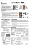
Figure 1
GXT5000R-208 UPS - Front view
Control panel
Air vents
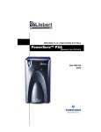
Figure 2
GXT5000R-208 UPS - Rear view
20A AC output
with circuit
breaker L6-20R
Input
cord
L6-30P
30A input
circuit
breaker
RELAYCARD-INT
alarm contacts
EPO
Cooling fans
30A AC
output
L6-30R
DC cable to external
battery cabinet
(see Figures 3 and 4)
208 VAC power to auxiliary
power input connector on
external battery cabinet
(see Figure 3)
7
DB-9 connector
No user connection
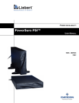
Figure 3
GXT5VBATTW120 battery cabinet with auxiliary 120 VAC
power - Rear view
DC cable from rear of
GXT5000R-208 to
external battery cabinet
(see Figure 2)
208 VAC power from rear of
GXT5000R-208 to auxiliary power
input connector (see Figure 2)
Auxiliary power
120 VAC @ 400 VA
with 4A circuit protector
Figure 4
Auxiliary power
input connector
GXT5VBATT battery cabinet - Rear view
External battery connectors
8
External battery
connectors
GENERAL INSTALLATION
1. Verify that the 30A input circuit breaker on the GXT5000R-208 is in the OFF position.
2. For GXT5VBATTW120 only - Connect the 208V, one-foot-long cord, from the rear of the
GXT5000R-208 to the mating external battery connector on the rear of the
GXT5VBATTW120.
3. Connect the L6-20P from the load to the L6-20R on the rear of the GXT5000R-208. Turn
on the 20A circuit breaker on the rear of the GXT5000R-208.
4. Verify that the EPO connector and jumper are in place.
5. Connect any 120V loads to the 5-15R receptacles on the rear of the GXT5VBATTW120, if
used. Verify that the 4A circuit protector is not tripped.
6. Connect the DC cable from the GXT5000R-208 to the first battery cabinet. If additional
battery cabinets are used, connect each battery cabinet to the next using the 18-inch
battery cable supplied with each additional cabinet.
7. Connect the input cord to the nearest L6-30 branch circuit receptacle.
The UPS is now ready to turn on. Power will be applied to the load (bypass mode) immediately
whenever the input 30A circuit breaker is initially closed. Please refer to the Operating
Instructions section of this manual before turning on the input circuit breaker.
9
CONTROLS AND INDICATORS
AC input
indicator
1-35%
36-55%
56-75%
76-95%
96-105%
OVERLOAD
1-35%
36-55%
56-75%
76-95%
96-100%
Fault
indicator
ON/Manual battery test
(Transfer to inverter)
On Inverter
indicator
Battery capacity
indicators
On bypass
indicator
Load level
indicators
Standby/Manual bypass
(Transfer to bypass)
ON/Manual Battery Test button
This button controls output power to connected load(s) and has two functions:
• Transfer load to inverter
• Manual battery test
Pressing the ON/Manual Battery Test button will transfer the load from bypass to
inverter in order to provide conditioned and protected power to the output power
receptacles. If the output is turned off using the Standby button
, pressing the ON
button will restart the load directly from the inverter.
To initiate a manual battery test, press the ON/Manual Battery Test button for at
least one second while operating from utility power and no alarm conditions are
present.
The manual battery test should be initiated with fully charged batteries (all Battery
Capacity LEDs on). The Battery Capacity LEDs will flash during the battery test.
Standby/Manual Bypass button
This button controls output power to connected load(s) and has dual functions:
• Standby
• Manual bypass
!
CAUTION
Pressing the Standby/Manual Bypass button during normal
operation while the inverter is on will transfer the load to bypass
power, if the bypass voltage and frequency are within a safe range.
Pressing the Standby/Manual Bypass button when the UPS is in
bypass mode will shut off power to the output receptacles and
connected loads. Turning the unit off leaves the UPS in standby
mode. To fully isolate the load from power, open the input circuit
breaker.
10
Load Level indicators - 4 green, 1 amber, 1 red LEDs
The Load Level indicators display the approximate load level at all times.
• The four green LEDs indicate acceptable levels up to 95%.
• The amber light comes on when the load level is 96-105%.
• The last LED at right (red) indicates an overload (more than 105%) and warns of imminent shutdown if the load is not reduced.
Battery Capacity indicators - 5 green LEDs
The GXT5000R-208 features an automatic battery test. The Battery Capacity LEDs display
the approximate level of battery reserves.
An automatic test occurs every 28 days if utility power has not been interrupted. Should the
battery fail this test, the Battery Capacity LEDs will flash and the failure code will be displayed.
Fault indicator - 1 red LED
The Fault indicator LED is illuminated if the UPS detects a problem. Also, one or more of the
Load Level/Battery Level indicators may be illuminated (refer to Troubleshooting).
On Bypass indicator - 1 amber LED
The On Bypass indicator LED is illuminated when the UPS is operating from bypass power.
On Inverter indicator - 1 green LED
The On Inverter indicator LED is illuminated when the UPS inverter is operating and supplying power to your connected loads.
AC Input indicator - 1 green LED
The AC Input indicator LED is illuminated when utility power is available and falls within
the input specification.
11
MODES OF OPERATION
Normal Mode Operation
During normal operation, utility power provides energy to the UPS. The filters, the power factor correction circuit and the inverter process this power to provide computer-grade power to
connected loads. The UPS maintains the batteries in a fully charged state.
AC input
indicator
(illuminated)
Fault
indicator
(NOT illuminated)
Battery capacity
indicators
On Inverter
indicator
(illuminated)
On bypass
indicator
(NOT illuminated)
ON/Manual
battery
test
Load level
indicators
(illuminated LEDs
indicate load level)
Standby/
Manual
bypass
Battery Mode Operation
The UPS will enter Battery mode if there is a power surge, extreme power drop, or utility failure. The battery system supplies power through the DC to DC converter to the inverter to
generate power for the connected load.
!
CAUTION
Turning off the UPS while in battery mode will shut off output power.
AC input
indicator
(NOT illuminated)
Fault
indicator
(NOT illuminated)
Battery capacity
indicators
On Inverter
indicator
(illuminated)
On bypass
indicator
(NOT illuminated)
12
ON/Manual
battery
test
Load level
indicators
(illuminated LEDs
indicate load level)
Standby/
Manual
bypass
Bypass Mode
Bypass mode provides an alternate path for utility power to the connected load in the unlikely
event of a UPS malfunction, such as overload, overtemperature, or an internal UPS failure.
AC input
indicator
(NOT illuminated)
Fault
indicator
(NOT illuminated)
Battery capacity
indicators
On Inverter
indicator
(NOT illuminated)
On bypass
indicator
(illuminated)
ON/Manual
battery
test
Load level
indicators
(illuminated LEDs
indicate load level)
Standby/
Manual
bypass
Battery Recharge Mode
Once utility power is restored, the UPS resumes normal operation and the Battery Charger
begins recharging the battery.
13
OPERATING INSTRUCTIONS
Turn On
Once the AC supply has been applied to the unit, power will be applied to the load (bypass
mode) immediately when the 30 A input circuit breaker is initially closed. Turn the unit ON
(inverter mode) by pressing the ON button once.
Manual Bypass
To manually put the unit in Bypass mode, press the Standby button
once. Pressing this
button once will cause the load to be transferred to bypass power. Pressing this button a second time will result in loss of power to the output receptacles and connected loads.
!
CAUTION
Pressing the Standby/Manual Bypass button during normal
operation while the inverter is on will transfer the load to bypass
power, if the bypass voltage and frequency are within a safe
range.
The bypass power path does NOT protect the connected
equipment from disturbances on the utility supply.
Standby
To put the unit in Standby mode, press the Standby button
mode.
!
while the unit is in bypass
CAUTION
Pressing the Standby/Manual Bypass button when the UPS is in bypass
mode will shut off power to the output receptacles and connected loads.
Turning the unit off leaves the UPS in standby mode. To fully isolate the
load from power, open the input circuit breaker.
14
OPTIONAL BATTERIES - PROGRAMMABLE RUN TIME
The GXT5000R-208 may be equipped with up to five battery GXT5VBATT cabinets. At least
one battery cabinet is required. The first battery cabinet may be a GXT5VBATTW120 if a
120V, 400VA auxiliary voltage source is needed.
The enhanced communication provides an estimated run time in minutes, taking into account
the number of battery cabinets and UPS load. The number of attached battery cabinets must
be programmed into the UPS for accurate time estimates.
Even when external monitoring software is not used, the enhanced accuracy is applied to the
low battery contact closure alarm provided by the standard relay alarm card.
The front control panel provides a convenient method of programming the number of battery
cabinets.
Programming the GXT5000R-208 for Battery Cabinet Count
Programming the UPS uses the ON button,
the Standby button, and the Load LEDs on
the front control panel (see illustration at
right).
The battery count display mode should be
entered only with the UPS load off.
The count should always be checked on new
installations to confirm the setting.
Five Batteries
Four Batteries
Three Batteries
Two Batteries
One Battery
Once the battery count is displayed, the user
has the option of leaving the battery count
unchanged or modifying the count to match
the number of attached battery cabinets.
In this mode, the Load LEDs function as Battery Count LEDs. On completion of the procedure, one to five Load LEDs illuminate to
indicate how many battery cabinets are connected to the GXT5000R-208 (see illustration
below).
One Battery Connected
Two Batteries Connected
Three Batteries Connected
Four Batteries Connected
Five Batteries Connected
15
Procedure to confirm the battery count
1. Apply AC input power to the UPS.
2. Turn the UPS output off using the Standby button. If the UPS is in inverter mode, the
load must first be transferred to bypass and then to off.
3. Once the UPS output is off, press and hold the Standby button continuously. The Standby
button must be held continuously for the duration of this procedure. The UPS will do
nothing for the first 10 seconds. After approximately 10 seconds, the LED display will
scroll and the horn will beep. When the LED display comes to rest (about 15 seconds after
first pressing the Standby button), the battery cabinet count will be displayed on the Load
LEDs. The count will display as long as the Standby button is continuously held.
4. If the Standby button is released at any time, the entire procedure must be restarted.
5. Once the battery count is displayed, or at any time if you wish to abort the procedure, you
may release the Standby button and restart the UPS using the ON button.
Procedure to change the battery count
This procedure required the simultaneous use of the Standby button and ON button. No other
UPS procedure calls for simultaneously pressing the Standby and ON buttons.
The first three steps of this procedure repeats Steps 1 through 3 in the Procedure to confirm the battery count. However, once the battery count is displayed, you have the option of
changing the count. As before, the Standby button must be held continuously for the entire
procedure. Releasing the button prematurely will require that the whole process be repeated.
1. Apply AC input power to the UPS.
2. Turn the UPS output off using the Standby button. If the UPS is in inverter mode, the
load must first be transferred to bypass and then to off.
3. Once the UPS output is off, press and hold the Standby button continuously. After
approximately 10 seconds, the LED display will scroll and the horn will beep. When the
LED display comes to rest (about 15 seconds after first pressing the Standby button), the
battery cabinet count will be displayed on the Load LEDs. The count will display as long
as the Standby button is continuously held.
4. If the displayed battery count is incorrect, press the ON button for 1 second while
simultaneously continuing to hold the Standby button. The display will scroll and the
horn will beep, and the battery count will be increased by one.
5. If the desired battery count has not been reached, repeat Step 4. The count can only be
increased. After a count of 5 is reached, the count will restart at 1.
6. Once the desired battery count is displayed—or at any time you wish to abort the
procedure—you may release the Standby button and restart the UPS using the ON
button.
16
COMMUNICATIONS
Do not exceed NEC Class 2 limits for any connection to the DB-25 connector on the Relay
Interface card, the DB-9 communication port, and the EPO connector.
Relay Interface Card
Your GXT5000R-208 comes equipped with the RELAYCARD-INT relay card. Connections
must not exceed NEC Class 2 limits.
The Intellislot® Interface for Relay Contacts card provides contact closures for remote monitoring of alarm conditions in your Liebert UPS, delivering signals for On Battery, On Bypass,
Low Battery, Summary Alarm, UPS Fault and On UPS.
The contacts are rated for 24 VAC or DC at 1A.
Pin Configuration
Table 1
Pin configuration
Pin
Function
Operation
1
UPS Fault
Closed if no UPS failure
2
Not Used
—
3
Not Used
—
4
UPS Fault
Closed if UPS fails
5
Summary Alarm*
Closed if SUMMARY ALARM* occurs
6
Summary Alarm*
Closed if no alarm conditions are present
7
Signal Ground (for UPS Any Mode Shutdown)
8
Not Used
—
9
Common – Low Battery
10
Low Battery
Closed if battery is OK
11
Low Battery
Closed if LOW BATTERY point occurs.
12
Not Used
—
13
Not Used
—
14
UPS Any Mode Shutdown (short to pin 7)
Not utilized on GXT5000R-208 - See EPO section
15
On UPS
Closed if ON UPS (inverter) power
16
On Battery
Closed if ON BATTERY power (Utility failure)
17
Common – UPS Fault, Summary Alarm,
On UPS, On Battery, On Bypass
18
On Battery
Closed if not ON Battery power (Utility OK)
19
Not Used
—
20
Not Used
—
21
Not Used
—
22
Not Used
—
23
Not Used
—
24
On Bypass
Closed if ON BYPASS
25
Not Used
—
A Summary Alarm occurs when any of the following four conditions exist:
1. Utility power is out of the acceptable range (voltage and/or frequency).
2. UPS is in BYPASS MODE (load not on Inverter power).
3. UPS Battery is LOW (< 2 minutes of battery power remaining).
4. UPS fault has occurred.
17
EPO
This unit is equipped with provisions for the terminal connections for a UPS Emergency
Power OFF Switch (EPO). The terminal is located on the rear of the UPS next to the DB-9
connector. If an EPO switch is used, it must have the characteristics of an emergency button—closed under normal conditions and held open mechanically when operated. If this connection is removed, the unit will not start up.
Connections must not exceed NEC Class 2 limits.
18
SERIAL COMMUNICATIONS
The UPStationGXT5000R-208 has a DB-9 serial port male connector on the rear of the unit.
Contact closure signals are not provided on this connector. Serial signals are provided on this
port and are assigned as follows:
PIN
DESCRIPTION
1,4,6,7,8,9
Do not connect
2
UPS RxD (typical RS-232 levels)
3
UPS TxD (typical RS-232 levels)
5
Common
REAR PANEL MALE DB-9
This port is not directly compatible with the Liebert M3LS9P9S serial communication cable
supplied with the UPS. A DB-9 adapter must be used to provide a standard Liebert UPS communication port.
A DB-9 adapter is included in the UPS accessory box. Attach the adapter to the UPS using the
captive screws.
DB-9 Adapter
FEMALE
FEMALE
2
2
3
3
5
5
Connects to Serial Cable
Connects to UPS
The DB-9 adapter will redirect the communication signals and provide a female DB-9 communication port suitable for connection to the Liebert M3LS9P9S serial communication.
Serial Cable
Connect the DB-9 adapter to your computer serial port using the Liebert M3LS9P9S serial
communication cable.
M3LS9P9S Cable - 9 Pin UPS to 9 Pin Serial Port for Serial Communications
MALE
2
3
5
FEMALE
2
3
5
Connects to DB-9 Signal Converter
Connects to Computer Serial Port
19
UPS COMMUNICATIONS WITH INTELLISLOT
Your GXT5000R-208 comes equipped with the RELAYCARD-INT relay card. The addition of
serial communications now expands the list of cards that may be used in the Intellislot.
The UPStation GXT5000R-208 UPS is equipped with an Intellislot bay to provide advanced
communication and monitoring options.
Liebert’s MultiLink™ software continually monitors the UPS via a serial cable and can shut
down your computer or server in the event of an extended power failure.
MultiLink can also be configured for use without the serial cable when the Intellislot SNMP/
Web card is installed in the UPS. Additionally, MultiLink can be configured to coordinate
shutdown across the network with other computers running MultiLink when you purchase a
MultiLink License Kit. For more information about the Intellislot SNMP/Web Card and MultiLink License Kits, please visit the Web site http://multilink.liebert.com or contact your local
dealer or Liebert representative.
Several option cards are available for use in the Intellislot bay of the UPStation GXT5000R208. The Intellislot SNMP/Web Card provides SNMP and Web-based monitoring and control
of the UPS across the network.
The Intellislot MultiPort 4 Card allows you to install MultiLink software on four computers
and coordinate an orderly shutdown in the event of a power failure.
The standard Intellislot Relay Card provides dry contact relay outputs for custom-wired
applications and delivers support for built-in shutdown for AS/400 systems.
!
CAUTION
TO MAINTAIN SAFETY (SELV) BARRIERS AND FOR ELECTROMAGNETIC
COMPATIBILITY, SIGNAL CABLES SHOULD BE SEGREGATED AND RUN
SEPARATE FROM ALL OTHER POWER CABLES, WHERE APPLICABLE.
20
MAINTENANCE
The GXT5000R-208 UPS requires very little maintenance. The batteries are valve-regulated,
nonspillable, lead acid and should be kept charged to obtain their design life. The UPS continuously charges the batteries when connected to the utility supply.
When storing the UPS for an extended period, connect it to utility power for at least 24 hours
every six months to keep the batteries fully charged.
!
CAUTION
Only qualified service personnel may replace internal batteries in
the battery cabinets.
21
TROUBLESHOOTING
This section presents various problems a user might encounter. Use this information to determine whether external factors cause the problem and how to remedy the situation.
1. The Fault LED will illuminate, indicating the UPS detected a problem.
2. An alarm will sound, alerting that the UPS requires attention.
3. One or more additional load/battery level LED indicators will be illuminated to provide a
diagnostic aid to the operator, as shown below:
A
Fault
LED
F
B
C
D
E
4. Record the LED condition and horn condition. Turn off the 30A AC input circuit breaker
on the rear of the UPS and restart the UPS based on the Operating Instructions in this
manual.
Table 2
LED indicators
LED status
Diagnosis
Audible alarm
All LEDs on
AC input overvoltage
Continuous beep
On bypass due to overtemperature condition until the UPS
cools, then re-transferring load to inverter.
Continuous beep
A, F on
Or off due to very high temperatures.
—
D, F on
Battery overvoltage
Continuous beep
E, F on
Battery mode overload
Half-second beep
every 1 second
A, D, F on
Inverter output short
Continuous beep
Line LED
flashing
Input AC present, but exceeds PFC input requirements
(> 276 or < 170)
—
All battery
capacity LEDs
flashing
Battery failure warning
Continuous beep
B, C, F on
EPO shutdown
Continuous beep
Other
Record condition of LEDs and horn. Contact Liebert technical
support.
—
If a problem persists, consult your local dealer, Liebert representative or the Liebert Worldwide Support Group—telephone numbers may be found on the back of this manual. Please
have the UPS model number and serial number available at the time of your inquiry.
22
Table 3
Fault
classification
Bus
fault
Inverter
fault
Troubleshooting guide
LED
display
C&F
LEDs
B&F
LEDs
Audible
alarm
Continuous
Continuous
Condition
± Bus V > 450 VDC
80 ms
± Bus V > 410 VDC
1.5 seconds
± Bus V < 230 VDC
80 ms
|(Abnormal + Bus V)-(|-Bus V |)| > 40 VDC or
|(+Bus V)-(Abnormal |-Bus V|)| > 35 VDC
2 minutes
Inverter output power > 276 VAC or
Inverter output power < 140 VAC
Minimum
90 ms
Inverter output power short. UPS short circuit
fault.
5 cycles
If temperature is > 90°F (32°C) detected
NTC’s temperature on CNTL pcb.
Overtemp
fault
A&F
LEDs
Continuous
Battery
overvoltage fault
D&F
LEDs
Continuous
Battery mode
overload alarm
E&F
LEDs
Response
time
5 seconds
If temperature > 65°F (18°C) and < 90°F
(32°C), then transfer to bypass mode, and
wait until temperature < 40°F (5°C) then back
to inverter mode
4.5 seconds
Battery voltage > 15V per unit
6.4 seconds
Battery mode load > 105%, < 125%
0.5 second
beep, recurring Battery mode load > 125%, < 150%
every 1 second
Battery mode load > 150%
1 minute
10 seconds
Instantaneous
Bypass
fault
A, B & F
LEDs
Continuous
Try to turn unit on (inverter mode). Check
output load for shorts.
Relay bonded
on N.O.
A, C & F
LEDs
Continuous
Check inverter output voltage, before inverter
soft start. If detected inverter output voltage Instantaneous
> 85 VAC, then set fault.
Inverter mode
output power
short circuit
fault
A, D & F
LEDs
Continuous
If detected inverter output power I > 70 ADC
and output voltage < 90 VDC, then increase
{short_cnt}.
If {short_cnt} > 30 any time in period of
96 ms, then set UPS short circuit fault.
Line LED
flash warning
—
—
Battery
disconnected
warning
BAT LED
flashing
Battery fail
warning
BAT LED
flashing
Continuous
When the UPS is in battery test sequence
and detected battery voltage < 10 VDC per
unit
Instantaneous
Bypass mode
bus overvoltage
or input voltage
too high fault
All LEDs bright,
buzzer beeping
Continuous
Bus overvoltage > 400 VDC or
input voltage > 292 VAC
Not specified
Input voltage
> 292 VAC
All LEDs bright,
buzzer beeping
Continuous
Check input voltage—must be greater than
292 VAC.
Not specified
BUS voltage
fault
All LEDs bright,
buzzer beeping
Continuous
Check the BUS voltage—must be lower than
242 VDC.
Not specified
Instantaneous
Not specified
Line voltage > 276 VAC
48 ms
Line voltage < 170 VAC
160 ms or
(48 ms)
0.5 second
UPS turn off charger and detected
beep, recurring When
battery
voltage < 10 VDC per unit
every 1 second
Instantaneous
23
SPECIFICATIONS
MODEL NUMBER
GXT5000R-208
MODEL RATING VA/W
5000 / 3750
DIMENSIONS: inches (mm)
Unit: W x D x H
16.1 x 23.6 x 5.1(410 x 600 x 130)
Shipping: W x D x H
23.2 x 31.1 x 12.8 (590 x 790 x 325)
WEIGHT: lbs (kg)
Unit
41.2 (18.7)
Shipping
53.8 (24.4)
INPUT AC PARAMETERS
Voltage Range
208 VAC Nominal: 176-276 VAC
Frequency
50/60 Hz, ±5%; Auto Sensing
Input Power Cord
10 ft. attached, w/ NEMA L6-30P
OUTPUT AC PARAMETERS
Output Receptacles
L6-30R (1), L6-20R (1)
Voltage
208 VAC, ±3%
Frequency
50 Hz or 60 Hz
Waveform
Sinewave
Main Mode Overload
151 - 300% for 2 seconds;
126 - 150% for 10 seconds;
105 - 125% for 60 seconds with transfer to bypass
DC INPUT PARAMETERS
Voltage
240 VDC Nominal
Recharge Time
8 Hours to 90% capacity after full discharge into 100% load
ENVIRONMENTAL
Operating Temperature
+32°F to +104°F (0°C to +40°C)
Storage Temperature
+5°F to +122°F (-15°C to +50°C)
Relative Humidity
0% to 95%, non-condensing
Operating Elevation
Up to 10,000 ft. (3000 m) at 104°F (40°C) without derating
Storage Elevation
50,000 ft. (15,000 m) maximum
Audible Noise
< 55 dBA
AGENCY
Safety
UL 1778, c-UL Listed
RFI/EMI
FCC Part 15, Subpart B, Class A
Transportation
ISTA Procedure 1A
24
BATTERY CABINET SPECIFICATIONS
GXT5VBATTW120
MODEL NUMBER
DIMENSIONS: inches (mm)
Unit: W x D x H
Shipping: W x D x H
WEIGHT: lbs (kg)
Unit
Shipping
AC PARAMETERS – AUXILIARY AC POWER
Nominal AC Input
Nominal AC Output
Output Receptacles
BATTERY PARAMETERS
Type
Qty. x Battery Voltage x Battery Rating
Battery Mfg./ Part #
ENVIRONMENTAL
Operating Temperature
Storage Temperature
Relative Humidity
Operating Elevation
AGENCY
Safety
RFI/EMI
Transportation
GXT5VBATTW120
16.1 x 23.6 x 5.1 (410 x 600 x 130)
23.2 x 31.1 x 12.8 (590 x 790 x 325)
121.7 (55.2)
132.3 (60.0)
208 VAC, 50/60 Hz, 400 VA, Single-Phase
120 VAC, 50/60 Hz, 400 VA, 0.75 PF (Power Factor)
5-15R (2)
Valve-regulated, nonspillable, lead acid
20 x 12 VDC x 28 watts per cell (10-minute rate)
Yuasa 28-12
+32°F to +104°F (0°C to +40°C)
+5°F to +122°F (-15°C to +50°C)
0% to 95%, non-condensing
Up to 10,000 ft. (3000 m) at 104°F (40°C) without derating
UL 1778, c-UL Listed
FCC Part 15, Subpart B, Class A
ISTA Procedure 1A
GXT5VBATT
MODEL NUMBER
DIMENSIONS: inches (mm)
Unit: W x D x H
Shipping: W x D x H
WEIGHT: lbs (kg)
Unit
Shipping
BATTERY PARAMETERS
Type
Qty. x Battery Voltage x Battery Amp Rating
Battery Mfg./ Part #
ENVIRONMENTAL
Operating Temperature
Storage Temperature
Relative Humidity
Operating Elevation
AGENCY
Safety
RFI/EMI
Transportation
GXT5VBATT
16.1 x 18.5 x 5.1 (410 x 470 x 130)
23.2 x 31.1 x 12.8 (590 x 790 x 325)
107.3 (48.7)
116.6 (52.9)
Valve regulated, nonspillable, lead acid
20 x 12 VDC x 28 watts per cell (10-minute rate)
Yuasa 28-12
+32°F to +104°F (0°C to +40°C)
+5°F to +122°F (-15°C to +50°C)
0% to 95%, non-condensing
Up to 10,000 ft. (3000 m) at 104°F (40°C) without derating
UL 1778, c-UL Listed
FCC Part 15, Subpart B, Class A
ISTA Procedure 1A
25
26
POWER AVAILABILITY
GXT5000R-208
with GXT5VBATTW120 / GXT5VBATT Battery Cabinets
The Company Behind the Products
With over a million installations around the globe,
Liebert is the world leader in computer protection
systems. Since its founding in 1965, Liebert has
developed a complete range of support and
protection systems for sensitive electronics:
•
•
•
•
•
Environmental systems—Close-control air
conditioning from 1 to 60 tons
Power conditioning and UPS with power
ranges from 300 VA to more than 1000 kVA
Integrated systems that provide both
environmental and power protection in a
single, flexible package
Monitoring and control—From systems of any
size or location, on-site or remote
Service and support through more than 100
service centers around the world and a 24/7
Customer Response Center
While every precaution has been taken to ensure
the accuracy and completeness of this literature,
Liebert Corporation assumes no responsibility and
disclaims all liability for damages resulting from
use of this information or for any errors or
omissions.
© 2002 Liebert Corporation
All rights reserved throughout the world.
Specifications subject to change without notice.
® Liebert and the Liebert logo are registered
trademarks of Liebert Corporation. All names
referred to are trademarks or registered
trademarks of their respective owners.
23156, Rev. 0 (7/02)
USER MANUAL
Technical Support/Service
Web Site
www.liebert.com
Monitoring
800-222-5877
[email protected]
Outside the US: 614-841-6755
Single-Phase UPS
800-222-5877
[email protected]
Outside the US: 614-841-6755
Three-Phase UPS
800-543-2378
[email protected]
Environmental Systems
800-543-2778
Outside the United States
614-888-0246
Locations
United States
1050 Dearborn Drive
P.O. Box 29186
Columbus, OH 43229
Italy
Via Leonardo Da Vinci 8
Zona Industriale Tognana
35028 Piove Di Sacco (PD)
+39 049 9719 111
Fax: +39 049 5841 257
Asia
23F, Allied Kajima Bldg.
138 Gloucester Road
Wanchai
Hong Kong
+852 2 572 2201
Fax: +852 2 831 0114