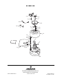
1
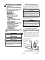
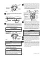
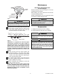
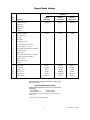
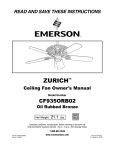
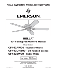
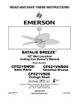
READ AND SAVE THESE INSTRUCTIONS
60” Industrial
Heat Fan
Owner's Manual
Net Weight:
19.8
Lbs.
Model No.
HF1160BK 00
HF1160BS 00
HF1160WW 00
LIMITED WARRANTY
What The Warranty Covers:
This warranty covers the motor and the other components and accessories of your Emerson ceiling fan against all defects in workmanship and materials.
You must be the original purchaser or user of the product to be covered.
What The Period Of Coverage Is:
As it applies to the motor, this warranty will last for five years from the date you purchased your ceiling fan. All other components and accessories are
covered by this warranty for one year from the date you purchased your ceiling fan. ANY IMPLIED WARRANTY OF MERCHANTABILITY OR FITNESS FOR A
PARTICULAR PURPOSE, MADE WITH RESPECT TO COMPONENTS AND ACCESSORIES IS ALSO LIMITED TO ONE YEAR.
What Will Emerson Electric Co. Do To Correct Problems:
Emerson Electric Co. will replace a defective Emerson Air Comfort Ceiling Fan motor, blade, component or other accessory at no charge to you. If repair of the
motor or blades is not practical or possible within a reasonable time and no replacement can be provided, Emerson Electric Co. will refund the actual purchase
price of your fan. We will ship the repaired product or replacement to you at no charge, but you are responsible for all costs or removal, reinstallation and
shipping of the product to Emerson Electric Co.
How Can You Get Service:
YOU MUST HAVE PROOF OF YOUR PURCHASE OF THE CEILING FAN TO OBTAIN LIMITED WARRANTY SERVICE. KEEP YOUR RECEIPT OR OTHER PROOF
OF PURCHASE. You can return the product to our factory or to your nearest authorized service center.
• To return the product to the factory, obtain a return authorization and service identification tag by writing to Air Comfort Products, Division of Emerson
Electric Co., 8100 W. Florissant Ave., St. Louis, MO 63136. Include all model numbers shown on the product with your request.
• To return the product to an authorized service center, call 1-800-654-3545 for the address of the nearest authorized service center.
You will be responsible for all insurance, freight or other transportation charges to our factory or authorized service center. Your Emerson Air Comfort
Ceiling Fan should be properly packed to avoid damage in transit since we will not be responsible for any such damage.
What Is Not Covered:
The glass globes and light bulbs of your ceiling fan are not covered by this warranty. This warranty also does not cover any defects, malfunctions or failures
caused by:
• Repairs by persons not authorized by Emerson Electric Co.,
• Use of parts or accessories not authorized by Emerson Electric Co.,
• Mishandling, improper installation, modifications or damage to your ceiling fan while in your possession, or
• Unreasonable use, misuse, abuse, including failing to do reasonable and necessary maintenance, and normal wear and tear.
Additionally, this warranty and any implied warranty of merchantability or fitness for a particular purpose are voided when:
• The original purchaser or user ceases to own the product, or
• The fan is moved from its original point of installation.
This warranty is only valid within the 50 states of the United States and the District of Columbia. No other written or oral warranties apply, and no employee,
agent, dealer or other person is authorized to give any warranties on behalf of Emerson Electric Co.
REPAIR, REPLACEMENT OR A REFUND ARE THE EXCLUSIVE REMEDIES AVAILABLE UNDER THIS WARRANTY AND EMERSON IS NOT RESPONSIBLE
FOR DAMAGES OF ANY KIND, INCLUDING INCIDENTAL AND CONSEQUENTIAL DAMAGES. Incidental damages include but are not limited to such damages
as loss of time and loss of use. Consequential damages include but are not limited to the cost of repairing or replacing other property which was damaged if
this product does not work properly.
How State Law Relates To The Warranty:
Some states do not allow the exclusion or limitation of incidental or consequential damages so the above exclusion or limitation may not apply to you.
This warranty gives you specific legal rights, and you may also have other rights which vary from state to state.
Part No. F40BP72720001
Form No. BP7272-1
U.L. Model No.: HF1160
!
WARNING
WARNING: To avoid fire, shock, and serious personal injury, follow these instructions.
Safety Instructions
1. Read your owner’s manual carefully and keep it for future reference.
2. Before servicing or cleaning unit, switch power off at service panel and lock service panel disconnecting
means to prevent power from being switched on accidentally. When the service disconnecting means cannot
be locked, securely fasten a warning device, such as a tag, to the service panel.
3. Be careful of the fan and blades when cleaning, painting, or working near the fan. Always turn off the power to
the ceiling fan before servicing.
4. Suitable for use with solid-state speed controls.
5. Do not bend the blade flanges when installing the blades, balancing the blades, or cleaning the fan. Do not
insert foreign objects in between the rotating blades.
Additional Safety Instructions for Installation
1. To avoid possible shock, be sure electricity is turned off at the fuse box before wiring, and do not operate fan
without blades.
2. All wiring must satisfy National and Local Electrical Codes. Use the National Electrical Code if Local Codes do
not exist. The ceiling fan must be grounded as a precaution against possible electrical shock. Electrical
installation should be made or approved by a licensed electrician.
3. The outlet box and joist must be securely mounted and capable of reliably supporting at least 50 pounds. Use
only U.L. outlet boxes listed as “Acceptable for Fan Support of 50 lbs or less”, and use the mounting screws
provided with the outlet box. Most outlet boxes commonly used for support of light fixtures are not acceptable
for fan support and may need to be replaced. Consult a qualified electrician if in doubt.
4. The fan must be mounted with the fan blades at least 10 feet from the floor to prevent accidental contact with
the fan blades.
5. Suitable for use with solid-state speed controls.
6. Always properly connect the safety cable included with this fan (follow the “Installation Instructions” section
carefully).
7. The support beam or joist must be secure and capable of supporting at least 50 pounds.
8. Follow the recommended instructions for the proper method of wiring your ceiling fan. If you do not know
enough about electrical wiring, have your fan installed by a licensed electrician.
WARNING: To avoid fire, shock or injury, do not use an Emerson or any other brand of control not specifically
approved for this fan.
WARNING: This product is designed to use only those parts supplied with this product and/or any accessories
designated specifically for use with this product by Emerson Electric Co. Substitution of parts or accessories not
designated for use with this product by Emerson Electric Co. could result in personal injury or property damage.
WARNING: To Reduce the risk of personal injury, do not bend the blade flange when installing the blade flanges,
balancing the blades or cleaning the fan. Do not insert foreign objects in between rotating fan blades.
DATE CODE:
The date code of this fan may be found on
the box, stamped in ink on a white label.
You should record this data above and keep
it in a safe place for future use.
2
U.L. Model No.: HF1160
Electrical Requirements
Your new ceiling fan will require a grounded electrical
supply line of 120 volts AC, 60 Hz, 15 amp circuit.
The outlet box must be securely anchored and
capable of withstanding a load of at least 50 pounds.
!
WARNING
To reduce the risk of fire, electric shock, or personal
injury, mount fan to outlet box marked “Acceptable
for Fan Support of 50 lbs. or less”, and use screws
supplied with outlet box. Most outlet boxes
commonly used for support of light fixtures are not
acceptable for fan support and may need to be
replaced. Consult a qualified electrician if in doubt.
If your fan is to replace an existing ceiling light fixture,
turn electricity off at the main fuse box at this time and
remove the existing light fixture.
!
WARNING
Turning off wall switch is not sufficient. To avoid
possible electrical shock, be sure electricity is turned
off at the main fuse box before wiring. All wiring must
be in accordance with National and Local codes and
the ceiling fan must be properly grounded as a
precaution against possible electrical shock.
Assembly Instructions
CAUTION: The blade assemblies must be
mounted on the motor assembly so that the “This
Side Up” label is visible at the top of the motor
(Figure 1).
1. Install one blade assembly on the top of the motor
assembly using two M6-1.0 x 12mm Phillips hex
head screws, two split lockwashers and two flat
washers (supplied) (Figure 1). Repeat this
procedure for the remaining two blade assemblies.
WARNING
Do not install or use fan if any part is damaged or
missing. Call Toll-Free:
1-800-654-3545
M6-1.0 x 12mm PHILLIPS
HEX HEAD SCREW
WARNING
SPLIT LOCKWASHER
This product is designed to use only those parts
supplied with this product and/or any accessories
designated specifically for use with this product by
Emerson Electric Co. Substitution of parts or
accessories not designated for use with this product
by Emerson Electric Co. could result in personal
injury or property damage.
SETSCREW (2)
FLAT WASHER
BLADE
ASSEMBLY
MOTOR
YOKE
LABEL
MOTOR ASSEMBLY
3
Figure 1
U.L. Model No.: HF1160
2. Using the setscrew wrench (supplied), remove the
two setscrews from the top of the motor yoke
(Figure 1). Retain the setscrews for future use.
3. Route the three 48” motor leads and the safety
cable through the center hole in the motor cover.
Align the two holes in the motor cover with the
threaded holes in the motor yoke and secure by
installing two M4-.7 x 10mm pan head knurled
screws and two M4 external tooth lockwashers
(supplied) (Figure 2).
M4-.7 x 10mm PAN HEAD
KNURLED SCREW
M4 EXTERNAL TOOTH
LOCKWASHER
!
WARNING
It is critical that the clevis pin in the motor coupling
is properly installed and the setscrews securely
tightened. Failure to verify that the pin and setscrews
are properly installed (as shown in Figure 3) could
result in the fan falling.
7. Install two setscrews (previously removed in
Step 2) in the motor yoke (Figure 3). While pulling
up on the hanger ball, securely tighten both
setscrews using the setscrew wrench (supplied).
NOTE: The setscrews must be properly installed
as described above, or fan wobble could result.
SAFETY
CABLE
MOTOR COVER
!
WARNING
The fan must be hung with at least 10' of clearance
from floor to blades (Figure 4).
CEILING
Figure 2
4. Route the three motor leads and the safety cable
through the center hole in the ceiling cover and
position the ceiling cover over the motor yoke
(Figure 3).
AT LEAST
10'
5. Separate, untwist and unkink the three motor leads
and the safety cable, then route them through the
hanger ball/downrod assembly and seat the
downrod in the motor yoke (Figure 3).
HANGER
BALL/DOWNROD
ASSEMBLY
FLOOR
Figure 4
SAFETY
CABLE
!
WARNING
The outlet box and joist must be securely mounted
and capable of supporting at least 50 lbs. Use only a
U.L. outlet box listed as “Acceptable for Fan Support
of 50 lbs. or less”.
CEILING COVER
HAIRPIN
CLIP
DOWNROD
MOTOR YOKE
!
SETSCREW
WARNING
To reduce the risk of fire, electric shock, or personal
injury, mount fan to outlet box marked “Acceptable
for Fan Support of 50 lbs. or less”, and use screws
supplied with outlet box. Most outlet boxes
commonly used for support of light fixtures are not
acceptable for fan support and may need to be
replaced. Consult a qualified electrician if in doubt.
CLEVIS
PIN
Figure 3
8. Securely attach the hanger bracket to the outlet
box using the two screws supplied with the
outlet box (Figure 5).
6. Align the clevis pin holes in the downrod with the
holes in the motor yoke. Install the clevis pin and
secure with the hairpin clip (Figure 3). The clevis
pin must go through the holes in the motor yoke It
is critical that the clevis pin in the motor yoke is
properly installed and the setscrews securely
tightened. Failure to verify that the pin and
setscrews are properly installed could result in the
fan falling.
!
WARNING
Hanger bracket must seat firmly against outlet box. If
the outlet box is recessed, remove wall board until
bracket contacts box. If bracket and/or outlet box are
not securely attached, the fan could wobble or fall.
4
U.L. Model No.: HF1160
11. Connect the green grounding wire from the
hanger ball, the green grounding wire from
the hanger bracket, and the green grounding wire
from the fan to the grounding conductor of the
supply (this may be a bare wire or wire with green
colored insulation). Securely connect wires with
wire connectors (supplied) (Figure 8).
OUTLET
BOX
TWO SCREWS
SUPPLIED WITH
OUTLET BOX
HANGER
BRACKET
BLACK
SUPPLY
(HOT)
BLACK FAN WIRE
GREEN WIRE
(GROUND) FROM FAN
SUPPLY GROUND
WIRE
GREEN WIRE
(GROUND) FROM
HANGER BALL
GREEN WIRE (GROUND)
FROM HANGER BRACKET
TAB
Figure 5
9. Screw the eye screw (supplied) into the joist
7 inches from the center of the ceiling outlet box
(Figure 6).
OUTLET BOX
EYE SCREW
7"
Figure 8
10. Carefully lift the fan and seat the hanger
ball/downrod assembly on the hanger bracket
that was just attached to the outlet box (Figure 7).
Be sure the groove in the ball is lined up with the
tab on the hanger bracket (Figure 5).
WARNING
Failure to seat tab in groove could cause damage to
electrical wires and possible shock or fire hazard.
!
NOTE: CEILING COVER,
SUPPLY WIRES AND
FAN WIRES OMITTED
FOR CLARITY.
HANGER
BRACKET
WARNING
To avoid possible fire or shock, do not pinch wires
between the hanger ball/downrod assembly and
hanger bracket.
If you feel that you do not have enough electrical
wiring knowledge or experience, have your fan
installed by a licensed electrician.
!
THREADED
STUD (2)
LISTED WIRE
CONNECTOR (3)
WARNING
13. Screw the two 3/4” threaded studs (supplied) into
the tapped holes in the hanger bracket (Figure 8).
14. Lift the ceiling cover up to the threaded studs and
turn until studs protrude through the holes in the
ceiling cover (Figure 9).
15. Secure the ceiling cover in place by sliding
lockwashers over the threaded studs and
installing the two knurled knobs (supplied)
(Figure 9). Tighten the knurled knobs securely
until the ceiling cover fits snugly against the
ceiling. Your fan is now wired to be turned on and
off from the wall switch.
HANGER BALL/
DOWNROD
ASSEMBLY
!
HANGER
BRACKET
Check to see that all connections are tight, including
ground, and that no bare wire is visible at the wire
connectors, except for the ground wire. Do not
operate fan until blades are in place. Noise and fan
damage could result.
OUTLET
BOX
Figure 8
WHITE
FAN WIRE
12. Securely connect the fan motor white wire to the
supply white (neutral) wire using wire connector
supplied (Figure 8). Securely connect the fan
motor black wire to the supply black (hot) wire
using wire connector supplied (Figure 8). After
connections have been made, turn leads upward
and carefully push the leads into the outlet box,
with the wires spread apart and the white and
green leads on one side of the outlet box and the
black leads on the other side of the outlet box.
Figure 6
!
WHITE
SUPPLY
(NEUTRAL)
WARNING
To avoid possible electrical shock, be sure electricity
is turned off at the main fuse box before wiring.
NOTE: If you are not sure if the outlet box is
grounded, contact a licensed electrician for advice,
as it must be grounded for safe operation.
5
U.L. Model No.: HF1160
Maintenance
SAFETY CABLE
IMPORTANT CARE INSTRUCTIONS
for your Ceiling Fan
CEILING
COVER
Periodic cleaning of your new ceiling fan is the only
maintenance that is needed.
When cleaning, use only a soft brush or lint free cloth
to avoid scratching the finish.
THREADED
STUDS (2)
Abrasive cleaning agents are not required and should
be avoided to prevent damage to finish.
#8 LOCKWASHER
KNURLED KNOB
Figure 9
!
!
Do not use water when cleaning your ceiling fan. It
could damage the motor or the blades and create the
possibility of an electrical shock.
WARNING
To avoid possible fire or shock, make sure that the
electrical wires are completely inside the outlet box and
not pinched between the ceiling cover and the ceiling.
Accessories
16. Pass the end of the safety cable through the two
cable clamps (supplied) (Figure 10). Pass the end
of the safety cable through the eye screw and
then back through the two cable clamps.
1. Ceiling Fan Controls (see store or catalog).
2. Downrod Extension Kits (see store or catalog).
!
EYE SCREW
WARNING
The use of any other control not specifically
approved for this fan could result in fire, shock and
personal injury.
TO FAN
Figure 10
WARNING
CABLE CLAMP
!
WARNING
This product is designed to use only those parts
supplied with this product and/or any accessories
designated specifically for use with this product by
Emerson Electric Co. Substitution of parts or
accessories not designated for use with this product
by Emerson Electric Co. could result in personal
injury or property damage.
CAUTION: It is important to note the proper
installation position of the cable clamps as
illustrated in Figure 10. TO obtain maximum
holding power, install U-bolt section of clip on
dead or short end of cable and saddle on long end
of cable. Improper installation reduces the
efficiency of the connection by as much as 40
percent.
17. After verifying that the cable clamps are
positioned properly on the safety cable, tighten
the nuts on the U-bolts. Leave one or two inches
of slack in the safety cable before tightening the
nuts. Cut off the excess cable.
18. If a remote speed control is to be used, refer to
the Owner’s Manual included with the control for
proper installation and wiring.
19. After completing the installation, restore the
power and test run the fan.
NOTE: When any solid state motor speed control
is used, a humming noise may be present in the
fan on low speed. This hum in no way affects the
operation of the fan and is acceptable in most
industrial installations.
6
U.L. Model No.: HF1160
Repair Parts Listing
Part Numbers
Key
No.
*
Description
Hanger Ball Assembly,
Model No.
Model No.
Model No.
HF1160BK 00
HF1160BS 00
HF1160WW 00
760750-46
761655-27
760750-47
—
—
—
Consisting of:
1
Hanger Bracket
2
Hanger Ball
—
—
—
3
Downrod
—
—
—
*
Parts Bag Containing:
762499
762499
762499
4
Wire Connector (3)
—
—
—
5
Pin, Clevis
—
—
—
6
Clip, Hairpin
—
—
—
7
Nut, Knurled, 8-32 (2)
—
—
—
8
Lockwasher, External Tooth, #8 (2)
—
—
—
9
Stud, Threaded, 8-32 x .75” (2)
—
—
—
10
Screw, Phillips Hex Head, M6-1.0 x 12mm (7)
—
—
—
11
Lockwasher, Split (7)
—
—
—
12
Washer, Flat (7)
—
—
—
13
Screw, Pan Head Knurled, M4-.7 x 10mm (2)
—
—
—
14
Lockwasher, External Tooth, M4 (2)
—
—
—
15
Wrench, Setscrew
—
—
—
16
Clamp, Safety Wire (2)
—
—
—
17
Screw, Eye
—
—
—
18
Cover, Ceiling
762516-3
762516-5
762516-15
19
Cover, Motor
762494
762494-BS
762494-1
20
Capacitor, 4.5 uF
762493
762493
762493
21
Blade (set of 3)
762495
762495-BS
762495-1
22
Flange (set of 3)
762497
762497-BS
762497-1
—
Owner's Manual
BP7272-1
BP7272-1
BP7272-1
Before discarding packaging material, be certain all parts
have been removed.
HOW TO ORDER REPAIR PARTS
WHEN ORDERING REPAIR PARTS, ALWAYS GIVE THE FOLLOWING
INFORMATION:
• PART NUMBER
• PART DESCRIPTION
• NAME OF ITEM
• MODEL NUMBER
The model number of your Fan will be found on a label attached to
the top housing.
For repair parts, phone 1-800-654-3545.
7
U.L. Model No.: HF1160
Repair Parts
3
1
2
9
15
4
18
16
8
7
17
13
14
19
10
11
12
6
PU EDIS
SIHT
5
21
22
20
Air Comfort Products
DIVISION OF EMERSON ELECTRIC CO.
8100 W. Florissant • St. Louis, MO 63136
Part No. F40BP72720001
Printed in China 01/08
Form No. BP7272-1
U.L. Model No.: HF1160