1
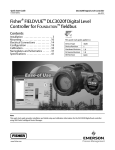
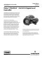
Product Bulletin
DLC3010 Digital Level Controller
11.2:DLC3010
August 2014
D102727X012
Fisherr FIELDVUEt DLC3010 Digital Level
Controller
The FIELDVUE DLC3010 digital level controller is used
with level sensors to measure liquid level, the level of
the interface between two liquids, or liquid specific
gravity (density). Changes in level or specific gravity
exert a buoyant force on a displacer, which rotates a
torque tube shaft. The digital level controller converts
this rotational motion to an electronic signal.
The DLC3010 is a communicating,
microprocessor-based instrument that can be
configured to sense the level, interface level, or
density of liquids. In addition to the normal function of
providing a 4 to 20 milliampere current signal, the
DLC3010, using HARTR communications protocol,
gives easy access to information critical to process
operation. You can obtain information about the
process, instrument, or sensor using the 475 or 375
Field Communicator. The DLC3010 can be used in
analog or HART digital signaling mode with the
Emerson Process Management DeltaVt system.
The connection for HART communication may be
made at any point in the field wiring that meets the
HART impedance requirements. Configuration,
calibration, diagnostics, parameter review, signal
monitoring and alert monitoring are all available
www.Fisher.com
W7977-1
through the HART protocol. Information from the field
can be integrated into control systems or be received
on a single loop basis.
The DLC3010 digital level controller is designed to
directly replace standard pneumatic and electronic
level transmitters. It mounts on a wide variety of Fisher
249 caged and cageless level sensors.
Product Bulletin
DLC3010 Digital Level Controller
11.2:DLC3010
August 2014
D102727X012
DLC3010 Digital Level Controller Specifications
Available Configurations
230 and 1100 ohms. The transmitter HART receive
impedance is defined as:
Rx: 42K ohms and
Cx: 14 nF
DLC3010 Digital Level Controller:
Mounts on caged and cageless 249 sensors. See
tables 4 and 5 and sensor description.
In point-to-point configuration, analog and digital
signalling are available. The instrument may be
queried digitally for information, or placed in Burst
mode to regularly transmit unsolicited process
information digitally. In multi-drop mode, the output
current is fixed at 4 mA, and only digital
communication is available.
Function: Transmitter
Communications Protocol: HART
Input Signal
Level, Interface, or Density: Rotary motion of torque
tube shaft proportional to changes in liquid level,
interface level, or density that change the buoyancy
of a displacer.
Performance
Process Temperature: Interface for 2- or 3-wire
100 ohm platinum RTD for sensing process
temperature, or optional user-entered target
temperature to permit compensating for changes in
specific gravity
Output Signal
Analog: 4 to 20 milliamperes DC (J direct
action—increasing level, interface, or density
increases output; or J reverse action—increasing
level, interface, or density decreases output)
High saturation: 20.5 mA
Low saturation: 3.8 mA
High alarm: 22.5 mA
Low Alarm: 3.7 mA
Performance
Criteria
DLC3010
Digital Level
Controller(1)
w/ 3-Inch
249W, Using
a 14-inch
Displacer
w/ All Other
249 Sensors
Independent
Linearity
$0.25% of
output span
$0.8% of
output span
$0.5% of
output span
Hysteresis
<0.2% of
output span
---
---
Repeatability
$0.1% of full
scale output
$0.5% of
output span
$0.3% of
output span
Dead Band
<0.05% of
input span
---
---
Hysteresis plus
Deadband
---
<1.0% of
output span
<1.0% of
output span
NOTE: At full design span, reference conditions.
1. To lever assembly rotation inputs.
Note: At effective proportional band (PB)<100%,
linearity, dead band, repeatability, power supply
effect, and ambient temperature influence are
potentially derated by the factor (100%/PB)
Only one of the above high/low alarm definitions is
available in a given configuration. NAMUR NE 43
compliant when high alarm level is selected.
Digital: HART 1200 Baud FSK (frequency shift keyed)
Operating Influences
HART impedance requirements must be met to
enable communication. Total shunt impedance
across the master device connections (excluding the
master and transmitter impedance) must be between
Power Supply Effect: Output changes <±0.2% of full
scale when supply varies between minimum and
maximum voltage specifications.
-continued-
Table of Contents
DLC3010 Specifications . . . . . . . . . . . . . . . . . . . . . . . . 2
Features . . . . . . . . . . . . . . . . . . . . . . . . . . . . . . . . . . . . . 7
Principle of Operation . . . . . . . . . . . . . . . . . . . . . . . . . 9
249 Level Sensor Specifications . . . . . . . . . . . . . . . . 10
249 Level Sensors . . . . . . . . . . . . . . . . . . . . . . . . . . . . 10
2
Installation . . . . . . . . . . . . . . . . . . . . . . . . . . . . . . . . .
Ordering Information . . . . . . . . . . . . . . . . . . . . . . . . .
Construction . . . . . . . . . . . . . . . . . . . . . . . . . . . . . . .
Heat Insulator . . . . . . . . . . . . . . . . . . . . . . . . . . . . . .
DLC3010 Digital Level Controller . . . . . . . . . .
12
12
13
13
13
Product Bulletin
DLC3010 Digital Level Controller
11.2:DLC3010
August 2014
D102727X012
DLC3010 Digital Level Controller Specifications (continued)
Transient Voltage Protection: The loop terminals are
protected by a transient voltage suppressor. The
specifications are as follows:
Pulse Waveform
Rise Time
(ms)
Decay to
50% (ms)
Max VCL
(Clamping
Voltage) (V)
Max IPP
(Pulse Peak
@ Current) (A)
10
1000
93.6
16
8
20
121
83
signal reasonableness monitor
User-configurable alarms: Hi-Hi and Lo-Lo Limit
process alarms
HART-readable only:
RTD signal reasonableness monitor: When RTD
installed
Processor free-time monitor.
Writes-remaining in Non Volatile Memory monitor.
User-configurable alarms: Hi and Lo limit process
alarms, Hi and Lo limit temperature alarms, Hi and Lo
limit electronics temperature alarms
Note: μs = microsecond
Ambient Temperature: The combined temperature
effect on zero and span without the 249 sensor is less
than 0.03% of full scale per degree Kelvin over the
operating range -40 to 80_C (-40 to 176_F)
Diagnostics
Output loop current diagnostic.
LCD meter diagnostic.
Spot specific gravity measurement in level mode: used
to update specific gravity parameter to improve
process measurement
Digital signal-tracing capability: by review of
“troubleshooting variables”, and
Basic trending capability for PV, TV and SV.
Process Temperature: The torque rate is affected by
the process temperature (see figure 1). The process
density may also be affected by the process
temperature.
Process Density: The sensitivity to error in knowledge
of process density is proportional to the differential
density of the calibration. If the differential specific
gravity is 0.2, an error of 0.02 specific gravity units in
knowledge of a process fluid density represents 10%
of span.
LCD Meter Indications
LCD meter indicates analog output on a percent scale
bar graph. The meter also can be configured to
display:
Electromagnetic Compatibility
Meets EN 61326‐1 and EN 61326‐2‐3
Immunity—Industrial locations per Table 2 of
EN 61326‐1 and Table AA.2 of EN 61326‐2‐3.
Performance is shown in table 1 below.
Emissions—Class A
ISM equipment rating: Group 1, Class A
Process variable in engineering units only.
Percent range only.
Percent range alternating with process variable or
Process variable, alternating with process temperature
(and degrees of pilot shaft rotation).
Electrical Classification
Supply Requirements (See figure 3)
Hazardous Area:
12 to 30 volts DC; instrument has reverse polarity
protection.
CSA— Intrinsically Safe, Explosion‐proof, Division 2,
Dust Ignition‐proof
A minimum compliance voltage of 17.75 is required
to guarantee HART communication.
FM— Intrinsically Safe, Explosion‐proof,
Non‐incendive, Dust Ignition‐proof
Compensation
ATEX— Intrinsically Safe, Type n, Flameproof
Transducer compensation: for ambient temperature.
Density parameter compensation: for process
temperature (requires user-supplied tables).
Manual compensation: for torque tube rate at target
process temperature is possible.
IECEx— Intrinsically Safe, Type n, Flameproof
Refer to tables 8, 9, 10, and 11 for additional approval
information.
Electrical Housing:
CSA— Type 4X
FM— NEMA 4X
ATEX— IP66
IECEx— IP66
Digital Monitors
Linked to jumper-selected Hi (factory default) or Lo
analog alarm signal:
Torque tube position transducer: Drive monitor and
-continued-
3
Product Bulletin
DLC3010 Digital Level Controller
11.2:DLC3010
August 2014
D102727X012
DLC3010 Digital Level Controller Specifications (continued)
Other Classifications/Certifications
FSETAN—Russian - Federal Service of Technological,
Ecological and Nuclear Inspectorate
GOST‐R—Russian GOST‐R
INMETRO— National Institute of Metrology,
Standardization, and Industrial Quality (Brazil)
NEPSI— National Supervision and Inspection Centre
for Explosion Protection and Safety of
Instrumentation (China)
PESO CCOE— Petroleum and Explosives Safety
Organisation - Chief Controller of Explosives (India)
TIIS— Technology Institution of Industrial Safety
(Japan)
Contact your Emerson Process Management sales
office for classification/certification specific
information
Minimum Differential Specific Gravity
With a nominal 4.4 degrees torque tube shaft
rotation for a 0 to 100 percent change in liquid level
(specific gravity=1), the digital level controller can be
adjusted to provide full output for an input range of
5% of nominal input span. This equates to a minimum
differential specific gravity of 0.05 with standard
volume displacers.
See 249 sensor specifications for standard displacer
volumes and standard wall torque tubes. Standard
volume for 249C and 249CP is ∼980 cm3 (60 in3),
most others have standard volume of ∼1640 cm3
(100 in3).
Operating at 5% proportional band will degrade
accuracy by a factor of 20. Using a thin wall torque
tube, or doubling the displacer volume will each
roughly double the effective proportional band.
When proportional band of the system drops below
50%, changing displacer or torque tube should be
considered if high accuracy is a requirement.
user, and a small performance loss is acceptable, the
instrument could be mounted in 90 degree rotational
increments around the pilot shaft axis. The LCD meter
may be rotated in 90 degree increments to
accommodate this.
Construction Materials
Case and Cover: Low-copper aluminum alloy
Internal: Plated steel, aluminum, and stainless steel;
encapsulated printed wiring boards; Neodymium Iron
Boron Magnets
Electrical Connections
Two 1/2-14 NPT internal conduit connections; one on
bottom and one on back of terminal box. M20
adapters available.
Options
J Heat insulator. See description under Ordering
Information. J Mountings for Masoneilan, Yamatake
and Foxboro/Eckhardt displacers available. J Level
Signature Series Test (Performance Validation
Report) available (EMA only) for instruments
factory-mounted on 249 sensor. J Factory
Calibration: available for instruments
factory-mounted on 249 sensor, when application,
process temperature and density(s) are supplied.
J Device is compatible with user-specified remote
indicator.
Operating Limits
Process Temperature: See table 3 and figure 2.
Ambient Temperature and Humidity: See below
Conditions
Normal
Limits(1)(2)
Ambient
Temperature
-40 to 80_C
(-40 to 176_F)
Ambient
Relative
Humidity
Mounting Positions
Digital level controller can be mounted right- or
left-of-displacer, as shown in figure 8.
Instrument orientation is normally with the coupling
access door at the bottom, to provide proper
drainage of lever chamber and terminal
compartment, and to limit gravitational effect on the
lever assembly. If alternate drainage is provided by
0 to 95%,
0 to 95%,
(non-condensing)
(non-condensing)
Nominal
Reference(1)
25_C
(77_F)
40%
1. LCD meter may not be readable below -20_C (-4_F)
2. Contact your Emerson Process Management sales office or application engineer if
temperatures exceeding these limits are required.
Weight
Less than 2.7 Kg (6 lbs)
NOTE: Specialized instrument terms are defined in ANSI/ISA Standard 51.1 - Process Instrument Terminology.
4
Transport and
Storage
Limits(1)
-40 to 85_C
(-40 to 185_F)
Product Bulletin
DLC3010 Digital Level Controller
11.2:DLC3010
August 2014
D102727X012
Table 1. EMC Summary Results—Immunity
Port
Enclosure
I/O signal/control
Test Level
Performance
Criteria(1)(2)
Phenomenon
Basic Standard
Electrostatic discharge (ESD)
IEC 61000‐4‐2
4 kV contact
8 kV air
A
Radiated EM field
IEC 61000‐4‐3
80 to 1000 MHz @ 10V/m with 1 kHz AM at 80%
1400 to 2000 MHz @ 3V/m with 1 kHz AM at 80%
2000 to 2700 MHz @ 1V/m with 1 kHz AM at 80%
A
Rated power frequency
magnetic field
IEC 61000‐4‐8
60 A/m at 50 Hz
A
Burst
IEC 61000‐4‐4
1 kV
A
Surge
IEC 61000‐4‐5
1 kV (line to ground only, each)
B
Conducted RF
IEC 61000‐4‐6
150 kHz to 80 MHz at 3 Vrms
A
Note: RTD wiring must be shorter than 3 meters (9.8 feet)
1. A = No degradation during testing. B = Temporary degradation during testing, but is self‐recovering. Specification limit = +/- 1% of span.
2. HART communication was considered as “not relevant to the process” and is used primarily for configuration, calibration, and diagnostic purposes.
5
Product Bulletin
DLC3010 Digital Level Controller
11.2:DLC3010
August 2014
D102727X012
Figure 1. Theoretical Reversible Temperature Effect on Common Torque Tube Materials
TORQUE RATE REDUCTION
(NORMALIZED MODULUS OF RIGIDITY)
1.00
0.98
1
0.96
0.94
N05500
Gnorm
0.92
N06600
0.90
N10276
0.88
0.86
0.84
0.82
S31600
0.80
20
40
60
80
100 120 140 160 180 200 220 240 260
280 300 320 340 360 380 400
420
TEMPERATURE (_C)
TORQUE RATE REDUCTION
(NORMALIZED MODULUS OF RIGIDITY)
1.00
0.98
1
0.96
Gnorm
0.94
0.92
N05500
N06600
0.90
N10276
0.88
0.86
0.84
0.82
0.80
S31600
50
100
150
200
250
300
350
400
450
500
550
TEMPERATURE (_F)
Note:
1 Due to the permanent drift that occurs near and above 260_C (500_F), N05500 is not recommended
for temperatures above 232_C (450_F).
6
600
650
700
750
800
DLC3010 Digital Level Controller
D102727X012
Features
n Simplified Setup and Calibration—For quick analog
transmitter replacement (4-20mA out only), the
instrument may be configured with default sensor
data, zero Level Offset, differential process SG, and
zero/span procedure only. For full compensation
and diagnostic capabilities, complete sensor data
entry and calibration is recommended.
Using Guided Setup, digital level controller start-up
is straightforward and fast. Level and temperature
alarms, specific gravity tables, calibration trim and
trending are readily configurable. The DLC3010 also
supports re-ranging without a fluid reference.
n Responsive to Small Process Changes—Accurate,
high-gain analog-to-digital conversion enables
measurement of small changes in the process
variable. This allows the DLC3010 to be used in
difficult liquid level, interface, or density
applications. In addition, an adjustable input filter
and output damping help to attenuate
displacer-induced ripple in the output signal due to
liquid turbulence.
n Reduced Temperature Effects—An internal
temperature sensor enables consistent
performance of the digital level controller despite
ambient temperature changes. With a temperature
input signal, either via HART protocol or an RTD
connected to the instrument, the digital level
controller can also automatically compensate for
specific gravity changes due to temperature. A
user-supplied table of up to ten linear segments
may be entered to implement this feature. (A
sample water/steam table is provided in the
DLC3010 instruction manual (D102748X012). The
measured torque tube rate may be manually
pre-compensated for a target process temperature
using the data available in the DLC3010 Device
Description (DD).
Product Bulletin
11.2:DLC3010
August 2014
n Additional Compensation—The instrument
measurement algorithm corrects for the small
motion of the displacer as buoyancy changes,
allowing it to calculate the true cage or vessel level.
This provides additional accuracy on the shorter
displacers.
n Rugged Construction—Mechanical safeguards
designed into the digital level controller help it to
withstand physical abuse often incurred during
installation or in transport, without compromising
performance. The fully encapsulated printed wiring
boards resist the effects of vibration, temperature,
and corrosive atmospheres. The lever assembly is
pinned at the neutral position when the coupling
access door is open, providing shipping stabilization
for a separate transmitter purchase. Locking set
screws are provided for covers and the access door
handle.
n Easy Maintenance—Field wiring connections are in a
compartment separated from the electronics. This
protects the electronics from any moisture brought
into the housing by the field wiring. This also eases
installation and maintenance. The digital level
controller does not have to be removed to facilitate
troubleshooting or service. Modular construction
(figure 4) allows servicing in the field. However, if it
is necessary to remove the digital level controller for
in-shop maintenance and calibration, field wiring
does not need to be disconnected.
n Alarm Jumper—The DLC3010 digital level controller
includes self-diagnostics that detect an error (e.g.
electronics failure) that would render the process
variable measurement inaccurate. The instrument
can also be configured to indicate a process variable
high or low alarm. When a process variable alarm or
an error is detected the analog output signal is
driven either above or below the normal 4 to 20 mA
range, depending on the user-selectable position of
the alarm jumper. The unit ships from the factory
with the jumper in the high position.
7
Product Bulletin
DLC3010 Digital Level Controller
11.2:DLC3010
August 2014
D102727X012
Figure 2. Guidelines for Use of Optional Heat
Insulator Assembly
Figure 3. Power Supply Requirements and Load
Resistance
Maximum Load = 43.5 X (Supply Voltage - 12.0)
10
20
30
40
50
60
TOO
HOT
HEAT INSULATOR
REQUIRED
400
70
80
425
400
300
200
100
NO HEAT
INSULATOR NECESSARY
0
1
HEAT
INSULATOR REQUIRED
TOO
-325 COLD
-40 -20
0
-100
0
20
40
60
80
-200
100 120 140
176 160
783
Load (Ohms)
0
-30 -20 -10
PROCESS TEMPERATURE (_C)
PROCESS TEMPERATURE (_F)
AMBIENT TEMPERATURE (_C)
-40
800
Operating
Region
250
AMBIENT TEMPERATURE (_F)
STANDARD TRANSMITTER
Notes:
1 For process temperature below -29_ (C-20_F) and above 204_C (400_F)
sensor materials must be appropriate for the process (refer to bulletin
34.2:2500).
2. If ambient dew point is above process temperature, ice formation might
cause instrument malfunction and reduce insulator effectiveness.
0
10
12
15
20
25
E0284
SUPPLY VOLTAGE (VDC)
39A4070-B
A5494-1
Figure 4. FIELDVUE DLC3010 Digital Level Controller Assembly
ADAPTER RING
TERMINAL BOX
TERMINAL BOX
COVER
LEVER ASSEMBLY
TRANSDUCER ASSEMBLY
ELECTRONICS
MODULE
LCD METER
ASSEMBLY
E1472
COVER
8
30
Product Bulletin
DLC3010 Digital Level Controller
11.2:DLC3010
August 2014
D102727X012
Principle of Operation
The DLC3010 digital level controller is a loop-powered
instrument that measure changes in liquid level, level
of an interface between two liquids, or density of a
liquid. A level, density, or interface level change in the
measured fluid causes a change in the displacer
buoyancy (figure 5). This change is transferred to the
torque tube assembly. As the measured fluid changes,
the torque tube assembly rotates.
The signal is interpreted as a buoyancy change by
reference to the stored torque rate, coupling point,
and moment arm data. The buoyancy change in turn is
interpreted as a level, interface, or density change by
reference to stored displacer volume, specific gravity,
and displacer length data. In level or interface modes,
the correction for displacer motion is then added, as
well as user-supplied offset to change the PV reference
from the bottom of the displacer or correct for a
coupling point error.
The rotary motion of the torque tube is transferred to
the digital level controller lever assembly (figure 5).
The rotary motion moves a magnet attached to the
lever assembly, changing the magnetic field that is
sensed by the Hall-effect sensor. The sensor converts
the magnetic field signal to a varying electronic signal,
which is processed digitally to provide linearity
corrections, sensitivity adjustment, and temperature
compensation.
The resultant primary variable (PV) is then compared
to PV alarm thresholds (if enabled) and used to set
status bits and/or trigger the analog alarm current. If
the alarm is not triggered, the PV is used to generate
4-20 mA analog and 0-100% range digital signals by
reference to the stored upper and lower range values.
The resultant analog command is limited at the
saturation values to allow discrimination between
saturated and alarm signals.
Figure 5. Cutaway View of Fisher 249 Displacer Sensor with FIELDVUE DLC3010 Digital Level Controller
TORQUE TUBE
E1471
DISPLACER
W1389-1
9
Product Bulletin
DLC3010 Digital Level Controller
11.2:DLC3010
August 2014
D102727X012
249 Level Sensors Specifications
Input Signal
Liquid Level or Liquid-to-Liquid Interface Level:From 0
to 100 percent of displacer length
Liquid Density: From 0 to 100 percent of
displacement force change obtained with given
displacer volume—standard volumes are J 980 cm3
(60 inches3) for 249C and 249CP sensors or
J 1640 cm3 (100 inches3) for most other sensors;
other volumes available depending upon sensor
construction
Sensor Displacer Lengths
See tables 4 and 5 footnotes
Sensor Working Pressures
Consistent with applicable ASME
pressure/temperature ratings for the specific sensor
constructions shown in tables 4 and 5
Caged Sensor Connection Styles
Cages can be furnished in a variety of end connection
styles to facilitate mounting on vessels; the
249 Level Sensors
equalizing connection styles are numbered and are
shown in figure 7.
Mounting Positions
Most level sensors with cage displacers have a
rotatable head. The head may be rotated through
360 degrees to any of eight different positions, as
shown in figure 8.
Construction Materials
See tables 2, 4, and 5
Operative Ambient Temperature
See table 3.
For ambient temperature ranges, guidelines, and use
of optional heat insulator, see figure 2.
Options
J Heat insulator, see description under Ordering
Information J Gauge glass for pressures to 29 bar at
232_C (420 psig at 450_F), and J Reflex gauges for
high temperature and pressure applications
Figure 6. FIELDVUE DLC3010 Digital Level Controller
and Fisher 249B Level Sensor
249 level sensors used with the DLC3010 digital level
controller are available in both caged and cageless
configurations. Figure 6 shows a DLC3010 mounted on
a caged 249 sensor. Caged sensors provide more
stable operation than do cageless sensors for vessels
with internal obstructions or considerable internal
turbulence. Cageless sensors are generally used on
specific gravity and interface control applications
requiring large displacers that are more easily
accommodated by flange connections up to 8 inches.
The availability of many different displacer stem
lengths permits lowering the displacer down to the
most advantageous depth in the vessel.
W7926
10
Product Bulletin
DLC3010 Digital Level Controller
11.2:DLC3010
August 2014
D102727X012
Table 2. Displacer and Torque Tube Materials
Part
Displacer
Standard Material
316 Stainless Steel,
N10276, N04400,
Plastic, and
Special Alloys
N10276, N04400,
other Austenitic
Stainless Steels, and
Special Alloys
316 Stainless Steel,
N06600, N10276
304 Stainless Steel
Displacer Stem,
Driver Bearing,
Displacer Rod and
Driver
316 Stainless Steel
Torque Tube
N05500(1)
Table 3. Allowable Process Temperatures for
Common Fisher 249 Sensor Pressure Boundary
Materials
Other Materials
PROCESS TEMPERATURE
MATERIAL
Cast Iron
Steel
1. N05500 is not recommended for spring applications above 232_C (450_F).
Contact your Emerson Process Management sales office or application engineer if
temperatures exceeding this limit are required.
Min.
Max.
-29_C (-20_F)
232_C (450_F)
-29_C (-20_F)
427_C (800_F)
Stainless Steel
-198_C (-325_F)
427_C (800_F)
N04400
-198_C (-325_F)
427_C (800_F)
Graphite Laminate/SST
Gaskets
-198_C (-325_F)
427_C (800_F)
N04400/PTFE Gaskets
-73_C (-100_F)
204_C (400_F)
Table 4. Caged Displacer Sensors(1)
TORQUE TUBE
ORIENTATION
Torque tube arm
rotatable with
respect to
equalizing
connections
SENSOR
STANDARD CAGE, HEAD,
AND TORQUE TUBE ARM
MATERIAL
249(3)
Cast Iron
249B, 249BF(4)
Steel
249C(3)
316 Stainless Steel
EQUALIZING CONNECTION
Style
Size (NPS)
PRESSURE RATING(2)
Screwed
1-1/2 or 2
Flanged
2
Screwed or optional socket weld
1-1/2 or 2
CL600
Raised face or optional ring type joint
flanged
1-1/2
CL150, 300, or 600
2
CL150, 300, or 600
Screwed
1-1/2 or 2
CL600
1-1/2
CL150, 300, or 600
2
CL150, 300, or 600
1-1/2 or 2
CL900 or 1500
2(5)
CL2500
Raised face flanged
249K
Steel
Raised face or optional ring type joint
flanged
249L
Steel
Ring type joint flanged
CL125 or 250
1. Standard displacer lengths for all styles (except 249) are 14, 32, 48, 60, 72, 84, 96, 108 and 120 inches. The 249 uses a displacer with a length of either 14 or 32 inches.
2. DIN flange connections available in EMA (Europe, Middle East and Africa).
3. Not available in EMA.
4. 249BF available in EMA only. Also available in DIN size DN40 with PN10 to PN100 flanges and size DN50 with PN10 to PN63 flanges.
5. Top connection is 1-inch ring-type joint flanged for connection styles F1 and F2.
Table 5. Cageless Displacer Sensors(1)
Mounting
Mounts on
top of vessel
Sensor
Standard Head(2), Wafer
Body(6), and Torque Tube
Arm Material
CL150, 300, or 600
NPS 6 or 8 raised face
CL150 or 300
NPS 3 raised face
CL150, 300, or 600
NPS 4 raised face or optional ring type joint
CL900 or 1500
(EN PN 10 to DIN PN 250)
NPS 6 or 8 raised face
CL150, 300, 600, 900, 1500, or
2500
Cast Iron, Cast Steel or
CF8M (316 Stainless Steel)
For NPS 4 raised face or flat face
CL125, 150, 250, 300, 900, or
1500 (EN PN 10 to DIN PN 160
For NPS 4 butt weld end, XXS
CL2500
WCC (steel) or CF8M
For NPS 3 raised face
CL150, 300, or 600
LCC (steel) or CF8M
For NPS 4 raised face
CL150, 300, or 600
Steel
249CP
316 Stainless Steel
Mounts on
side of vessel
249VS
Mounts on top of
vessel or on
customer supplied
cage
249W
Pressure Rating(3)
NPS 4 raised face or optional ring type joint
249BP(4)
249P(5)
Flange Connection
Steel or Stainless Steel
1. Standard displacer lengths are 14, 32, 48, 60, 72, 84, 96, 108, and 120 inches.
2. Not used with side-mounted sensors.
3. DIN flange connections available in EMA (Europe, Middle East and Africa).
4. Not available in EMA.
5. 249P available in EMA only.
6. Wafer Body only applicable to 249W.
11
Product Bulletin
DLC3010 Digital Level Controller
11.2:DLC3010
August 2014
D102727X012
Figure 7. Style Number of Equalizing Connections
STYLE 3
UPPER AND LOWER SIDE CONNECTIONS,
SCREWED (S-3) OR FLANGED (F-3)
STYLE 1
TOP AND BOTTOM CONNECTIONS,
SCREWED (S-1) OR FLANGED (F-1)
28B5536-1
B1820-2
STYLE 4
UPPER SIDE AND BOTTOM CONNECTIONS,
SCREWED (S-4) OR FLANGED (F-4)
STYLE 2
TOP AND LOWER SIDE CONNECTIONS,
SCREWED (S-2) OR FLANGED (F-2)
Installation
Ordering Information
A 249 sensor may be shipped with the DLC3010 digital
level controller installed or they may be shipped
separately.
When ordering, specify:
n Process temperature and pressure and ambient air
temperature
When shipping a skid mounted system, where the
displacer cannot be restrained, it is recommended that
the transmitter be uncoupled and the lever assembly
locked to prevent damage. The transmitter must be
re-coupled at commissioning, and a zero-trim will be
required.
Dimensions for the DLC3010 and 249 sensor product
construction are shown in figure 9 and tables 6 and 7.
Dimensions of other combinations are available upon
request.
12
n Application
n Liquid level service (specific gravity)
n Interface level service (specific gravity of both
liquids and minimum differential gap or span
required)
n Density service (minimum and maximum specific
gravity required)
Product Bulletin
DLC3010 Digital Level Controller
11.2:DLC3010
August 2014
D102727X012
Figure 8. Typical Mounting Positions for FIELDVUE DLC3010 Digital Level Controller on Fisher 249 Sensors
SENSOR
LEFT-OF-DISPLACER
RIGHT-OF-DISPLACER
3
7
1
6
5
8
5
4
2
1
1
CAGED
1
4
3
2
8
6
7
CAGELESS
1 Not available for NPS 2 CL300 and 600 249C.
Construction
Heat Insulator
Refer to the specifications tables. Review the
descriptions below each specification and in the
referenced tables and figures; specify the desired
choice whenever there is a selection to be made.
DLC3010 Digital Level Controller
If the DLC3010 and the 249 sensor are ordered as an
assembly, and a heat insulator is required for the
application, order the heat insulator as a 249 sensor
option. If the DLC3010 is ordered separately, the heat
insulator is available as a kit. Order part number
28B5741X012 for the heat insulator kit.
13
Product Bulletin
DLC3010 Digital Level Controller
11.2:DLC3010
August 2014
D102727X012
Figure 9. Dimensions for FIELDVUE DLC3010 Digital Level Controller Mounted on a Fisher 249B Sensor
(also see tables 6 and 7)
1-1/2 11-1/2 NPT
103
(4.06)
421
(16.56)
244
(9.62)
MATCH
LINE (B)
102.1
(4.02)
G
A
503.4
(19.83)
203
(8.00)
F
125.7
(4.95)
1/2-14 NPT
CONDUIT
CONN
W
A
M
73.7
(2.90)
202.4
(7.97)
106
(4.19)
1/2-14 NPT
CONDUIT CONN
102.6
(4.04)
3/4-14 NPT
DETAILED FRONT VIEW OF
DLC3010 DIGITAL LEVEL CONTROLLER
TOP VIEW
S-3 AND F-3 UPPER AND
LOWER SIDE CONNECTIONS
mm
(INCH)
25.F83
19A3071
19A8853-D
17B0219-A
18B5524-1
B1822-5
Table 6. Dimension A for FIELDVUE DLC3010 Digital Level Controller Mounted on a Fisher 249B Sensor
A
SIZE
(NPS)
1-1/2
2
Screwed NPT
CL150 RF
CL150 RTJ
CL300 RF
CL300 RTJ
CL600 RF
CL600 RTJ
mm
Inches
mm
Inches
mm
Inches
mm
Inches
mm
Inches
mm
Inches
mm
Inches
121
121
4.75
4.75
145
145
5.69
5.69
152
151
6.00
5.94
148
148
5.81
5.81
154
155
6.06
6.12
154
157
6.06
6.19
159
159
6.25
6.25
DIN(1)
SIZE
PN10/PN16
PN25/PN40
PN63
PN100
mm
mm
mm
mm
143
145
145
147
153
153
153
---
DN40
DN50
1. Dimension A for 249BF with din flanges.
Table 7. Dimensions F, G, M, and W for FIELDVUE DLC3010 Digital Level Controller Mounted on a Fisher 249B Sensor
DISPLACER LENGTH
14
F
G
M
W
mm
Inches
mm
Inches
mm
Inches
mm
Inches
mm
Inches
356
14
356
14.00
197
7.75
284
11.19
394
15.50
813
32
813
32.00
425
16.75
513
20.19
851
33.50
Product Bulletin
DLC3010 Digital Level Controller
11.2:DLC3010
August 2014
D102727X012
Table 8. Hazardous Area Classifications for Canada—CSA
Certification Body
Certification Obtained
Intrinsically Safe
Class I,II,III Division 1 GP A,B,C,D,E,F,G
per drawing 28B5744 T6
CSA
Entity Rating
Vmax = 30 VDC
Imax = 226 mA
Ci = 5.5 nF
Li = 0.4 mH
Temperature Code
T6 (Tamb ≤ 80°C)
Explosion-proof
Class I, Division 1 GP B,C,D T6
---
T6 (Tamb ≤ 80_C)
Class I Division 2 GP A,B,C,D T6
Class II Division 1, 2 GP E,F,G T6
Class III
---
T6 (Tamb ≤ 80°C)
Entity Rating
Temperature Code
Table 9. Hazardous Area Classifications for United States—FM
Certification Body
Certification Obtained
Intrinsically Safe
Class I,II,III Division 1 GP A,B,C,D,E,F,G
per drawing 28B5745 T5
FM
Vmax = 30 VDC
Imax = 226 mA
Pi = 1.4 W
Ci = 5.5 nF
Li = 0.4 mH
T5 (Tamb ≤ 80°C)
Explosion-proof
Class I, Division 1 GP A,B,C,D
---
T5 (Tamb ≤ 80_C)
Class I Division 2 GP A,B,C,D
Class II Division 1 GP E,F,G
Class II Division 2 GP F,G
---
T5 (Tamb ≤ 80°C)
Entity Rating
Temperature Code
Table 10. Hazardous Area Classifications—ATEX
Certificate
ATEX
Certification Obtained
Intrinsically Safe
II 1 G D
Gas
Ex ia IIC T5 Ga
Dust
Ex ia IIIC T83_C Da IP66
Flameproof
II 2 G D
Gas
Ex d IIC T5 Gb
Dust
Ex tb IIIC T83_C Db IP66
Type n
II 3 G D
Gas
Ex nA IIC T5 Gc
Dust
Ex t IIIC T83_C Dc IP66
Ui = 30 VDC
Ii = 226 mA
Pi = 1.4 W
Ci = 5.5 nF
Li = 0.4 mH
T5 (Tamb ≤ 80_C)
---
T5 (Tamb ≤ 80_C)
---
T5 (Tamb ≤ 80_C)
15
Product Bulletin
DLC3010 Digital Level Controller
11.2:DLC3010
August 2014
D102727X012
Table 11. Hazardous Area Classifications—IECEx
Certificate
IECEx
Certification Obtained
Intrinsically Safe
Gas
Ex ia IIC T5 Ga
Dust
Ex ia IIIC T83_C Da IP66
Flameproof
Gas
Exd IIC T6 Gb
Dust
Ex t IIIC T83_C Db IP66
Type n
Gas
Ex nA IIC T5 Gc
Dust
Ex t IIIC T83_C Dc IP66
Entity Rating
Ui = 30 VDC
Ii = 226 mA
Pi = 1.4 W
Ci = 5.5 nF
Li = 0.4 mH
Temperature Code
T5 (Tamb ≤ 80°C)
---
T5 (Tamb ≤ 80°C)
---
T5 (Tamb ≤ 80°C)
Neither Emerson, Emerson Process Management, nor any of their affiliated entities assumes responsibility for the selection, use or maintenance
of any product. Responsibility for proper selection, use, and maintenance of any product remains solely with the purchaser and end user.
Fisher, FIELDVUE, and DeltaV are marks owned by one of the companies in the Emerson Process Management business unit of Emerson Electric Co. Emerson
Process Management, Emerson, and the Emerson logo are trademarks and service marks of Emerson Electric Co. HART is a mark owned by the HART
Communication Foundation. All other marks are the property of their respective owners.
The contents of this publication are presented for informational purposes only, and while every effort has been made to ensure their accuracy, they are not
to be construed as warranties or guarantees, express or implied, regarding the products or services described herein or their use or applicability. All sales are
governed by our terms and conditions, which are available upon request. We reserve the right to modify or improve the designs or specifications of such
products at any time without notice.
Emerson Process Management
Marshalltown, Iowa 50158 USA
Sorocaba, 18087 Brazil
Chatham, Kent ME4 4QZ UK
Dubai, United Arab Emirates
Singapore 128461 Singapore
www.Fisher.com
E
162000, 2014 Fisher Controls International LLC. All rights reserved.