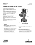
1
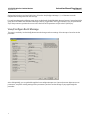
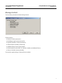
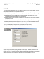
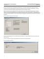
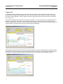
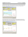
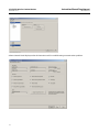
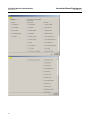
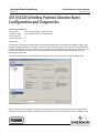
Instruction Manual Supplement 4310/4320 Wireless Position Monitor D103794X012 November 2013 4310/4320 Wireless Position Monitor Burst Configuration and Diagnostics This document applies to: Fisherr 4320 Device Type 1308 (hex) 4872 (decimal) TopWorx™ 4310 Device Type E0CE (hex) 57550 (decimal) Device Revision 4 Firmware Revision 5 DD Revision 1 This document will guide you through burst configuration and diagnostics using AMS Device Manager. Burst can be configured similarly using the 475 Field Communicator. Refer to the appropriate instruction manual [D103622X012 (4310) or D103621X012 (4320)], available from your Emerson Process Management sales office, or www.Fisher.com, for the Field Communicator menu trees, as well as 4310/4320 wireless position monitor installation, setup and maintenance information. Access burst configuration in the Broadcast Information group from the Wireless tab in Configure, Manual Setup. When connected at the maintenance port, this screen shows the Network ID and the Basic content assignment for each burst message. When AMS is communicating with the device over the wireless network, these variables are not www.Fisher.com 4310/4320 Wireless Position Monitor November 2013 Instruction Manual Supplement D103794X012 displayed to help the screen load a little faster. Select the View/Configure Message 0, 1, or 2 buttons to see the complete burst configuration for that message. For each Burst Message the following menu items are displayed: Enabled/Disabled, Message Content, Content Details (this group bears the label of the selection in Message Content), Trigger Mode, and Trigger Parameters. For an explanation of any of the parameters, position the cursor in the value box for the parameter and press the F1 (HELP) key. View/Configure Burst Message This menu is readonly. Use the Modify button to make changes to these settings. Select Accept or Cancel to exit the procedure. After clicking Modify, you are guided through the burst configuration process. If you only want to adjust one or two parameters, accept the existing settings for the parameters you don’t need to change as you page through the procedure. 2 Instruction Manual Supplement 4310/4320 Wireless Position Monitor D103794X012 November 2013 Message Content The first choice presented is the basic Message Content. Choose between: D Primary Variable (command 1) D PV %Range, Loop Current (command 2) D Dynamic Variables, Current (command 3) D Selected Device Variables (command 9) D Additional Device Status (command 48) D Emerson Specific (command 178 Dynamic Variables and Additional Status) D Discrete Variables (command 64386) The normal or typical setting is “Selected Device Variables”. 3 4310/4320 Wireless Position Monitor Instruction Manual Supplement November 2013 D103794X012 Contents Three of the Message Content choices allow you to adjust the fine detail of the burst message contents. Assign basic content to the messages based on your application requirements: D If the device is a monitor and you only need to track one parameter, you may be able to use only one message bursting the Primary Variable. D If you need to track only 2 or 3 variables and the alerts, you could enable 2 messages and assign Dynamic Variables and Current to one and Additional Device Status to the other. D If you are using an Emerson Gateway that configuration can be reduced to a single active message bursting the Emerson Specific content. D If you have a lot of parameters to track, Selected Device Variables will probably be used for at least one message. D If you are using many parameters but need some at a faster rate than others, you could assign Selected Device Variables as the basic content of two different messages, assign the fast update variables to one of them and the slow variables to the other, and schedule their publication accordingly. D For On/Off control devices, you must publish Discrete Variables in one of the messages. Selected Device Variables (Command 9) is one of the choices that allow detailed content adjustment: SELECTED DEVICE VARIABLES IS THE NORMAL OR TYPICAL SETTING FOR AN ON/OFF CONTROL APPLICATION You may assign the desired device variables to individual slots in the message. The variable placed in the first slot becomes the Trigger Variable when burst trigger modes other than Continuous or OnChange are selected, so it is advisable that the variable in that slot be chosen carefully. Using a variable that never changes, like Loop Current, or one that dithers, such as Temperature, might be a poor choice for certain trigger modes. Usually the Trigger Variable should be the parameter whose change is most representative of the process state you are monitoring. 4 Instruction Manual Supplement 4310/4320 Wireless Position Monitor D103794X012 November 2013 Some of the available device variables are not computed in the device in a given structure or operating mode. These are marked with an asterisk in the dropdown list that appears when you edit a slot. Dynamic Variables and Current (Command 3) is the second choice that allows detailed adjustment: 5 4310/4320 Wireless Position Monitor Instruction Manual Supplement November 2013 D103794X012 Here you can edit the 2nd, 3rd, and 4th Dynamic Variable slots. The Primary Variable is fixed. Loop Current is also published in this command, although it is always Not a Number, Bad, and Constant in the wireless device. The Loop Current value is sometimes needed by control system hosts, such as a DeltaV™ system. Make certain that any information that the host needs from the device is being published by the device in a timely manner. If data is not being published, it is not available in the Gateway cache and the network manager application will have to send a special request to the device to obtain that data every time a host requests it. This behavior uses up a lot of the available bandwidth, and the network can become clogged if too many devices have data that is not being published. Emerson Specific (Command 178) is the third: Here you can also edit the 2nd, 3rd, and 4th Dynamic Variable slots. The Trigger Variable is the Primary Variable in the above two cases. If there are no slots to configure in the detailed content, the content is simply displayed. Primary Variable (Command 1): 6 Instruction Manual Supplement D103794X012 4310/4320 Wireless Position Monitor November 2013 PV % Range, Loop Current (Command 2): Additional Device Status (Command 48): Discrete Variables (Command 64386): 7 4310/4320 Wireless Position Monitor November 2013 Instruction Manual Supplement D103794X012 Burst Trigger Mode You are then asked to select the Trigger Mode (Continuous, Windowed, Rising, Falling, or OnChange). Continuous and Windowed are used in the majority of applications. The function of each of these modes is discussed below. Some basic content choices, such as PV %Range +Loop Current, Additional Device Status, Emerson Specific, and Discrete Variables, have limited triggering capability. In those cases only the available trigger modes are displayed, e.g.: The burst message can be published continuously at a constant rate, or it can be configured for fast publishing when trigger conditions are met, with slower publishing as the default. This is often termed “Report by Exception”. Instead of Continuous, choose one of the “triggered” modes: Windowed, Rising, Falling, or OnChange. 8 Instruction Manual Supplement 4310/4320 Wireless Position Monitor D103794X012 November 2013 Trigger Parameters / Scheduling This menu structure varies based on the Message Content and Trigger Mode selections. Update Rates If you select Continuous trigger mode, the only parameter that is adjustable is the Triggered Update Rate. When the selected trigger mode is other than Continuous, a Default Update Rate is added to the parameters to be configured. The message will be published at the Default Update Rate until the trigger condition is met. When the trigger condition has been met, the message will be published at the Triggered Update Rate for at least 3 transmissions. Then, if the trigger condition is no longer met, the message will revert to publication at the slower Default Update Rate. Note that the legal values of the update rate parameters are somewhat restricted. The longest permitted value is 1 hour (3600 seconds), the shortest usable value may be limited by the Gateway capability and network loading. Values below 60 seconds must be factors of 2: (e.g., 32, 16, 8, 4, 2, or 1). Sensor Sample Rate and Delayed Triggering When the trigger mode of any message is other than Continuous, the device employs a userconfigured Sensor Sample Rate for acquiring all of the processrelated variables. The value of this variable may be adjusted between 0.5 second and the Triggered Update Rate in increments of 0.5 second. (Exception: for External Power devices, the Sensor Sample Rate is fixed at the fastest rate possible in the device, since battery life is not a concern.) The edit procedure compares this value against the configured Triggered Update Rate of any other enabled burst message whose trigger mode is not Continuous, to help prevent setting it slower than the fastest existing rate. If the Sensor Sample Rate is faster than the Triggered Update Rate, enabling Delayed Triggering allows the device to latch and timestamp a message as soon as the trigger condition is met, then schedule publishing at the next available Triggered Update Rate time slot. This mode is called “Delayed” because the message is published a short time after the data was captured. However, it allows capture of a transient event that might have been missed by only checking for changes at the Triggered Update Rate. 9 4310/4320 Wireless Position Monitor November 2013 Instruction Manual Supplement D103794X012 Trigger Level For Windowed, Rising, and Falling trigger modes, there is also a Burst Trigger Level to configure. The procedure now automatically sets Trigger Class and Trigger Units to the values of the Burst Trigger Variable’s Class/Units. Accordingly, the class is no longer displayed. The Burst Trigger Variable and Trigger Units are presented for reference in setting the Burst Trigger Level. If you select Windowed trigger mode, the Burst Trigger Level defines a +/ zone around the previous published value of the Burst Trigger Variable. This mode is used when steady state operation is expected and increased timedomain resolution is desired only when the process is changing rapidly. Adjust the Burst Trigger Level to set how much the Burst Trigger Variable must deviate from its previous value to trigger fast publishing. In Rising trigger mode, the trigger level defines an upper threshold. This mode is used when process operation below a specified level is of little consequence, but operation above that level needs to be tracked in greater detail. Adjust the Burst Trigger Level to define the desired upper threshold that must be exceeded to meet the trigger condition. 10 Instruction Manual Supplement D103794X012 4310/4320 Wireless Position Monitor November 2013 In Falling trigger mode, the trigger level defines a lower threshold. This mode is used when process operation above a specified level is of little consequence, but operation below that level needs to be tracked in greater detail. Adjust the Burst Trigger Level to define the desired lower threshold that must be exceeded to meet the trigger condition. In OnChange trigger mode, the entire message is the trigger source, and any deviation from the previous value satisfies the trigger condition. Therefore, the Burst Trigger Variable, Trigger Units and Burst Trigger Level do not appear. This mode is most useful for discrete value message content such as Additional Device Status and Discrete Variables. It should not be used on messages that contain data that may dither. 11 4310/4320 Wireless Position Monitor November 2013 Instruction Manual Supplement D103794X012 Enabled/Disabled Select Enabled to request network bandwidth allocation for this burst message. Select Disabled to terminate publication of this burst message and release bandwidth allocation back to the network. Summary — Accept/Modify After the editing process is complete, the summary screen of the entire burst configuration with your changes is shown for review. If the configuration meets your approval, click the Accept button to send the changes to the device. If you want to make additional changes, click the Modify button to loop through the procedure again. If after any pass through the edit loop, you decide that you don’t want to make the changes after all, click the Cancel button and all pending changes will be discarded. 12 Instruction Manual Supplement 4310/4320 Wireless Position Monitor D103794X012 November 2013 Set All Burst Messages to Default For initial configuration, after modifying the device structure, this procedure will establish a reasonable set of burst parameters that will allow normal operation. It can also be useful to recover from any burst configuration experiments that lead to communication problems. The following tables describe the default settings that result for each structure and device type. Burst Configuration Details Message Basic Content 0 Selected Device Variables 1 Additional Status 2 Discrete Variables Trigger Mode Device Structure Windowed Controller w/ Snap Disabled Controller w/ Snap Enabled Monitor On Change X(1) On Change Controller w/ Snap Disabled Controller w/ Snap Enabled Monitor Message Enabled/Disabled Triggered Update Rate Default Update Rate Enabled 8 sec 1 min Enabled 16 sec 1 min Enabled 4 sec 1 min Enabled 1 min 1 hr Enabled 8 sec 1 min Enabled 1 min 10 min Disabled 1 min 10 min Delayed Triggering Disabled Enabled Disabled 1. X indicates that the Device Structure does not matter. Sensor Sample Rate Device Structure Battery Power Controller w/Snap Disabled 8 sec Controller w/ Snap Enabled 1 sec Monitor 1 sec External Power 50 msec 13 Instruction Manual Supplement 4310/4320 Wireless Position Monitor D103794X012 November 2013 Detailed Default Burst Contents for Selected Device Variables and corresponding Dynamic Variable Assignments TopWorx 4310 Device Structure Trigger Controller w/Snap Disabled Controller w/Snap Enabled Monitor Switch States Switch States Switch States Trigger Level 0.0 0.0 0.0 2 Set Point Set Point Transition Dwell 3 Supply voltage Supply voltage Supply Voltage 4 Loop current Loop current Loop current 5 Cycle Counter Cycle Counter Cycle Counter 6 Last Open Stroke Temperature Opened/High Dwell 7 Last Close Stroke Time Stamp 0 Closed/Low Dwell 8 Temperature (Not Used) Time Stamp 0 PV Switch States Switch States Switch States 2nd Set Point Set Point Switch States 3rd Cycle Counter Cycle Counter Cycle Counter 4th Supply Voltage Supply Voltage Supply Voltage Selected Device Variable Assignments Dynamic Variables The 4320 has additional Device Variables related to Position, so the default slot assignments are different than in the 4310: Detailed Default Burst Contents for Selected Device Variables and corresponding Dynamic Variable Assignments Fisher 4320 Device Structure Selected Device Variable Assignments Dynamic Variables 14 Controller w/Snap Disabled Controller w/Snap Enabled Monitor Trigger Switch States Position Position Trigger Level 0.0 5.0% 5.0% 2 Set Point Set Point Switch States Supply Voltage 3 Position Switch States 4 Supply voltage Supply voltage Loop current 5 Loop current Loop current Cycle Counter 6 Cycle Counter Cycle Counter Opened/High Dwell 7 Last Open Stroke Temperature Closed/Low Dwell 8 Last Close Stroke Time Stamp 0 Time Stamp 0 PV Position Position Position 2nd Set Point Set Point Switch States 3rd Switch States Switch States Cycle Counter 4th Supply Voltage Supply Voltage Supply Voltage Instruction Manual Supplement 4310/4320 Wireless Position Monitor D103794X012 November 2013 Tailor Burst Configuration This procedure will tailor the content and triggering of the 3 burst messages to your device structure and application without requiring you to edit any actual settings. Your responses to a series of questions are used to select one of 14 predefined configurations. The cycling and reporting times have the most influence on update and sample rates, and the structure and application have the most influence on the detailed message content. Tailored Burst Configuration Message 0 Basic Content Selected Device Variables Trigger Mode Device Structure/Application 1 2 Discrete Variables Triggered Update Rate Default Update Rate 10 min Controller w/ Snap Disabled Slow Cycle 1 min Fast Cycle 8 sec 1 min Controller w/ Snap Enabled Slow Cycle 1 min 10 min Windowed Fast Cycle 1 min 10 min Enabled Slow/Fast(1) 16 sec 10 min Disabled Fast/Fast(1) 4 sec 1 min Disabled Relief Valve 4 sec 1 min Enabled 1 min 1 hr Enabled X(2) Controller w/ Snap Disabled Slow Cycle 1 min 10 min Fast Cycle 8 sec 1 min Controller w/ Snap Enabled Monitor X(2) 1 min 10 min 1 min 10 min On Change Disabled 1 min Enabled X(2) On Change Delayed Triggering 16 sec Slow/Slow(1) Monitor Additional Status Message Enabled /Disabled Enabled X(2) Enabled Disabled Disabled 1. “Slow/Slow” etc. means “Slow Cycle, Slow Report”, respectively. 2. X indicates that the Device Structure/Application does not matter. Sensor Sample Rate Device Structure / Application Controller w/Snap Disabled Controller w/ Snap Enabled Monitor Battery Power Slow Cycle Fast Cycle Slow Cycle Fast Cycle 8 sec 1 sec 16 sec 1 sec Slow Cycle/Slow Report 16 sec Slow Cycle/Fast Report 4 sec Fast Cycle/Fast Report 1 sec Relief Valve 1 sec External Power 50 msec 15 Instruction Manual Supplement 4310/4320 Wireless Position Monitor D103794X012 November 2013 Detailed Tailored Burst Contents for Selected Device Variables and corresponding Dynamic Variable Assignments TopWorx 4310 Device Structure Closed/Low Limit Tripped 0.0 General Normally Opened 0.0 0.0 Set Point Set Point Switch States Switch States Transition Dwell Switch States 3 Supply voltage Supply voltage Supply voltage Supply Voltage Supply Voltage Supply Voltage Switch States Switch States Switch States 0.0 Opened/High Limit Tripped 0.0 4 Loop current Loop current Loop current Loop current Loop current Loop Current 5 Cycle Counter Cycle Counter Cycle Counter Cycle Counter Cycle Counter Cycle Counter Temperature Opened/High Dwell Opened/High Dwell Opened/High Dwell Opened/High Dwell Time Stamp 0 Closed/Low Dwell Closed/Low Dwell Closed/Low Dwell Closed/Low Dwell (Not Used) Time Stamp 0 Time Stamp 0 Time Stamp 0 Time Stamp 0 Switch States 8 Last Open Stroke Last Close Stroke Temperature PV Switch States 7 Switch States Switch States Switch States Closed/Low Limit Tripped Opened/High Dwell Cycle Counter Opened/High Limit Tripped Cycle Counter Supply Voltage Supply Voltage Supply Voltage 2nd Set Point Set Point 3rd Cycle Counter Cycle Counter Closed/Low Limit Tripped Cycle Counter 4th Supply Voltage Supply Voltage Supply Voltage Switch States Switch States Detailed Tailored Burst Contents for Selected Device Variables and corresponding Dynamic Variable Assignments Fisher 4320 Device Structure Controller Snap Disabled Monitor Snap Enabled Normally Closed Relief Valve Closed/Low Limit Tripped 0.0 General Normally Opened Trigger Level 0.0 5.0% Closed/Low Limit Tripped 0.0 5.0% Opened/High Limit Tripped 0.0 2 Set Point Set Point Switch States Switch States Switch States Switch States 3 Position Switch States Position Position Supply Voltage Position 4 Supply voltage Supply voltage Supply Voltage Supply Voltage Loop current Supply Voltage Trigger Switch States Position Position 5 Loop current Loop current Loop Current Loop Current Cycle Counter Loop Current 6 Cycle Counter Cycle Counter Cycle Counter Cycle Counter Opened/High Dwell Cycle Counter Temperature Opened/High Dwell Opened/High Dwell Closed/Low Dwell Closed/Low Dwell Time Stamp 0 Time Stamp 0 Time Stamp 0 Time Stamp 0 Time Stamp 0 Position Position Position 7 8 PV 16 Relief Valve 2 6 Dynamic Variables Normally Closed Trigger Level Selected Device Variable Assignments Selected Device Variable Assignments Monitor Snap Enabled Closed/Low Limit Tripped 0.0 Trigger Dynamic Variables Controller Snap Disabled Last Open Stroke Last Close Stroke Position Position Position Switch States Switch States Cycle Counter Cycle Counter Supply Voltage Supply Voltage 2nd Set Point Set Point Switch States 3rd Switch States Switch States Cycle Counter Closed/Low Limit Tripped Opened/High Dwell 4th Supply Voltage Supply Voltage Supply Voltage Supply Voltage Instruction Manual Supplement D103794X012 4310/4320 Wireless Position Monitor November 2013 Communication Diagnostics The Communications diagnostics menu item in the Service Tools menu contains Network, Burst, Hardware Triggering, and Events diagnostics. Network The Network tab shows the current Connection Status and Join Mode. Connection Status echoes the simplified ‘CONN’ status variable that appears in the device Local User Interface. It can take on the following states: Init, Idle, Disconnected, Searching, Connected, and Operational. The Join Mode reports the condition under which the device will automatically try to join the network whose credentials are stored in its configuration. This parameter is not useradjustable, The Disconnect procedure allows you to remove the device from the network if you are doing maintenance that would interfere with network operation, or are retiring or recommissioning the device for some other application. If you are connected to the device at the Maintenance Port, additional menu items are available. The information in Advanced Network Details might be difficult to obtain from the Gateway if you were actually having communications problems, and would add additional network traffic as well. The Rejoin Network procedure will only work when you are connected to the device at the Maintenance Port. 17 4310/4320 Wireless Position Monitor November 2013 Instruction Manual Supplement D103794X012 Advance Network Details displays technical information useful in troubleshooting communications problems. 18 Instruction Manual Supplement 4310/4320 Wireless Position Monitor D103794X012 November 2013 The Join Details group shows: Wireless Mode This is the full state of the wireless connection as defined in the HCF (HARTr Communication Foundation) specifications. D Idle The device is inactive and has no knowledge of the wireless network. Its wireless transceiver is not active. D Active Search The device is listening for network traffic, synchronizing to the network clock, and identifying neighbors. D Negotiating The device is presenting its credentials to the network manager and requesting a session key and network key. D Quarantined The device has been integrated into the network and has been assigned normal super frames and links, but does not yet have a Gateway session. It may not forward data packets, only originate or receive them. D Operational The device has obtained a Gateway session and is being assigned bandwidth and communication resources. D Suspended The device is inactive. All of its network tables are intact. D Deep Sleep The device is in an ultralow power state, scheduled to wake up and reenter Active Search after a long interval. Neighbor Count This indicates the number of neighbors recognized by the instrument on the wireless network. Advertisement Count This indicates the number of Advertisement packets received. Join Attempts This indicates the number of Join Attempts. (Too many join attempts will result in the device considering the join failed.) Network Search Time This indicates the amount of time spent listening for the first advertisement. Join Retry Timer This indicates the amount of time since the last join request was sent. It does not freeze after the join is completed, but keeps incrementing. Note Some versions of AMS will display this as a negative number if the most significant bit is set, even though it is an unsigned integer. For display, the value has to be rescaled to seconds from its native scaling of 1/32 of a millisecond per bit, and the misinterpretation probably occurs during the scaling process. Join Status — This indicates device progress in joining the network. D Wireless Signal Found Network packets have been recognized. D Wireless Signal Identified D WirelessHARTr Signal Identified D Wireless Time Synchronized Device clock has been aligned with host or gateway. D Network Admission Requested A join request has been transmitted. D Join Retrying The number of join requests issued is greater than 2. This state will be cleared when the device is authenticated or when 'Active Search' mode restarts on wake up from 'Deep Sleep'. D Join Failed The join mode has switched from 'Active Search' to 'Deep Sleep'. The device will wake up later and try again. (Join Failed is a degraded condition and all the other bits in Join Status are positive in nature. The Join Failed bit was accordingly given a ‘redbulb’ treatment.) 19 4310/4320 Wireless Position Monitor Instruction Manual Supplement November 2013 D103794X012 D Network Security Clearance Granted A Network Manager session has been established. D Network Joined Negotiating Network Properties. Gateway session obtained. D Join Complete Device is enrolled in the network and in normal operating mode. The Radio group displays the configured Transmit Power Level and provides a procedure for changing it if required. BURST The Burst tab shows diagnostics for each burst message: The message Bandwidth Status shows: D whether a given message is enabled in the device D whether it is still waiting for bandwidth allocation from the network for its requested update rate D whether it has been assigned bandwidth but at a lower rate than requested D whether it is actively publishing D whether it is in Delayed Publishing mode (Using Delayed Trigger mechanism) The configured Message Content, Trigger Mode, (requested) Triggered Update Rate and the Triggered Update Rate that has been allocated for the device by the network are displayed below the Bandwidth Status. If When the message is enabled, a button will allows you to view a snapshot of the values that would be published in the message, based on the current device states. This feature was originally developed for checking the behavior of 20 Instruction Manual Supplement D103794X012 4310/4320 Wireless Position Monitor November 2013 the burst configuration while connected at the maintenance port, since the actual publication of the messages in not supported over that interface. Example snapshots of 3 common burst messages are shown below. Help strings are available for each of the menu items. 21 4310/4320 Wireless Position Monitor November 2013 22 Instruction Manual Supplement D103794X012 Instruction Manual Supplement D103794X012 4310/4320 Wireless Position Monitor November 2013 23 4310/4320 Wireless Position Monitor November 2013 Instruction Manual Supplement D103794X012 Hardware Triggering The device has a hardware mechanism that can wake up the processor to evaluate triggering thresholds early if a comparator detects a change in the input sensor signal. This menu displays the ChangeDetection thresholds versus temperature, provides a reset procedure for the Change Detect counter, and allows the Change Detection circuit to be enabled or disabled. It is available only in batterypowered devices, since devices with the external power option always sample on a 50 millisecond period, and thus don’t need this feature. 24 Instruction Manual Supplement D103794X012 4310/4320 Wireless Position Monitor November 2013 Events Although the Event Notification mechanism may not be enabled from the DD interface a menu has been provided to review the states of the Event Notification system. This menu displays the state of the event notification system for troubleshooting purposes. A button that lets you read and/or clear the event log appears when the event log has entries. 25 4310/4320 Wireless Position Monitor November 2013 Instruction Manual Supplement D103794X012 Neither Emerson, Emerson Process Management, nor any of their affiliated entities assumes responsibility for the selection, use or maintenance of any product. Responsibility for proper selection, use, and maintenance of any product remains solely with the purchaser and end user. Fisher, TopWorx, and DeltaV are marks owned by one of the companies in the Emerson Process Management business unit of Emerson Electric Co. Emerson Process Management, Emerson, and the Emerson logo are trademarks and service marks of Emerson Electric Co. HART and WirelessHART are marks owned by the Hart Communication Foundation. All other marks are the property of their respective owners. The contents of this publication are presented for informational purposes only, and while every effort has been made to ensure their accuracy, they are not to be construed as warranties or guarantees, express or implied, regarding the products or services described herein or their use or applicability. All sales are governed by our terms and conditions, which are available upon request. We reserve the right to modify or improve the designs or specifications of such products at any time without notice. Emerson Process Management Marshalltown, Iowa 50158 USA Sorocaba, 18087 Brazil Chatham, Kent ME4 4QZ UK Dubai, United Arab Emirates Singapore 128461 Singapore www.Fisher.com 26 E 2013 Fisher Controls International LLC. All rights reserved.