1
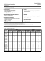
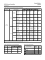
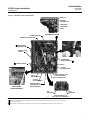
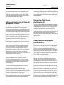
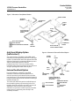
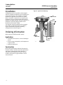
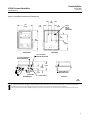
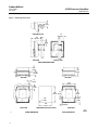
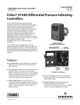
Product Bulletin
4195K Pressure Controllers
34.5:4195K
July 2014
D200050X012
Fisherr 4195K Gauge Pressure Indicating
Controllers
Fisher 4195K gauge pressure indicating controllers
show process pressure and set point on an
easy‐to‐read process scale. The controllers compare
process pressure with an operator‐adjusted set point
and delivers a pneumatic signal to a control element so
that process pressure changes toward the set point.
Controller types are available for proportional‐only,
proportional‐plus‐reset, proportional‐plus‐reset‐
plus‐rate, and differential gap for on‐off control. 4195K
controllers are used in industries where accurate
pressure control and process monitoring are required.
Unless otherwise noted, all NACE references are to
NACE MR0175-2002.
1
2
W5660‐1
INTERIOR OF A FISHER 4195KBME CONTROLLER
W5663‐1
YOKE‐MOUNTED CONTROLLER
Notes:
1 An internal cover protects the proportional band adjustment mechanism. In this photograph, the cover has been removed.
2 Controller components are indicated in figure 1.
www.Fisher.com
Product Bulletin
4195K Pressure Controllers
34.5:4195K
July 2014
D200050X012
Specifications
Supply Pressure Medium
Available Configurations
Air or natural gas(3)
See table 1
Remote Set Point Pressures
Process Sensor Range (Input Signal)
0.2 to 1.0 bar (3 to 15 psig) or 0.4 to 2.0 bar
Lower and Upper Range Limits:
As shown in tables 2 and 5
Maximum Allowable Pressure:
As shown in tables 2 and 5
(6 to 30 psig)
Construction Materials
See table 6
Process Scale
Controller Adjustments
Standard scale is matched to the range of the sensing
element, with exception of receiver controllers.
Optional scales available(1).
Proportional Band: 5 to 500% of process scale span
Reset: Adjustable from 0.01 to more than 74 minutes
per repeat (from 100 to less than 0.0135 repeats per
minute)
Rate: Adjustable from 0 to 20 minutes
Differential Gap Controllers: Adjustable from 5 to
100% of process scale span
Set Point: Adjustable from 0 to 100% of the scale span
Process Connections
Standard: 1/4 NPT internal stainless steel (all input
ranges)
Optional: 1/2 NPT adaptors (see table 3)
Controller Performance
Output Signal
Repeatability: 0.4% of output span
Dead Band: Less than 0.4% of process scale span
Typical Frequency Response: 1.5 hertz and 90 degree
phase shift with 3.05 m (10 feet) of 6.4 mm (1/4‐inch)
tubing and 1639 cm3 (100 cubic inch) volume
Proportional, Proportional‐Plus‐Reset, or
Proportional‐Plus‐Reset‐Plus‐Rate Range: 0.2 to
1.0 bar (3 to 15 psig) or 0.4 to 2.0 bar (6 to 30 psig)
Differential Gap Range: 0 to 1.4 bar (0 to 20 psig) or
0 to 2.4 bar (0 to 35 psig)
Action: Field‐reversible between direct (increasing
sensed pressure increases output pressure), and
reverse (increasing sensed pressure decreases
output pressure) action
Steady‐State Air Consumption(4)(5)
0.2 to 1.0 Bar (3 to 15 Psig) Output:
0.09 m3/hr (3.5 scfh)
0.4 to 2.0 Bar (6 to 30 Psig) Output:
0.13 m3/hr (5.0 scfh)
Supply and Output Connections
Delivery Capacity(4)
1/4 NPT internal
0.2 to 1.0 Bar (3 to 15 Psig) Output:
6.4 m3/hr (240 scfh)
0.4 to 2.0 Bar (6 to 30 Psig) Output:
9.4 m3/hr (350 scfh)
Supply Pressure Requirements(2)
See table 4
(continued)
Table of Contents
Features . . . . . . . . . . . . . . . . . . . . . . . . . . . . . . . . . . . . . 4
Construction Features . . . . . . . . . . . . . . . . . . . . . . . . . 4
Principle of Operation . . . . . . . . . . . . . . . . . . . . . . . . . 8
Proportional-Only Controllers . . . . . . . . . . . . . . . . . . 8
Proportional-Plus-Reset and
Proportional-Plus-Reset-Plus Rate Controllers . . 8
Differential Gap Controllers . . . . . . . . . . . . . . . . . . 10
Remote Set Point Option . . . . . . . . . . . . . . . . . . . . 10
2
Auto/Manual Station Option . . . . . . . . . . . . . . . . . .
Anti-Reset Windup Option . . . . . . . . . . . . . . . . . . .
External Feedback Option . . . . . . . . . . . . . . . . . . . .
Installation . . . . . . . . . . . . . . . . . . . . . . . . . . . . . . . . .
Ordering Information . . . . . . . . . . . . . . . . . . . . . . . . .
Application . . . . . . . . . . . . . . . . . . . . . . . . . . . . . . . .
Construction . . . . . . . . . . . . . . . . . . . . . . . . . . . . . . .
10
11
11
12
12
12
12
Product Bulletin
4195K Pressure Controllers
34.5:4195K
July 2014
D200050X012
Specifications (continued)
Exhaust Capacity(4)
0.2 to 1.0 Bar (3 to 15 Psig) Output:
5.0 m3/hr (186 scfh)
0.4 to 2.0 Bar (6 to 30 Psig) Output:
7.9 m3/hr (295 scfh)
Housing
Operative Ambient Temperature Limits(2)(6)
-40 to 71C (−40 to 160F)
Mounting
Designed to NEMA 3 (Weatherproof) and IEC 529
IP54 Specifications
Hazardous Area Classification
Complies with the requirements of ATEX Group II
Category 2 Gas and Dust
Controller can be mounted on actuator, panel,
wall, or pipestand
Approximate Weight
4.5 kg (10 pounds)
NOTE: Specialized instrument terms are defined in ANSI/ISA Standard 51.1 - Process Instrument Terminology.
1. Consult your Emerson Process Management sales office for additional information.
2. The pressure/temperature limits in this document and any applicable code or standard should not be exceeded.
3. This product can be used with natural gas. Natural gas should not contain more than 20 ppm of H2S.
4. Normal m3/hr‐‐normal cubic meters per hour (m3/hr, 0C and 1.01325 bar, absolute). Scfh‐‐standard cubic feet per hour (ft3/hr, at 60F and 14.7 psig).
5. Without auto/manual station. With auto/manual station air consumption is 0.28 normal m3/hr (10.0 scfh).
6. Also use these temperatures for transportation and storage limits.
Table 1. Available Configurations
MODES
TYPE
NUMBER(1)
OPTIONS
Proportional‐
Only
Proportional‐
Plus‐Reset
4195KA
4195KAE
4195KAM
4195KAME
4195KB
4195KBE
4195KBF
4195KBFE
4195KBM
4195KBME
4195KBFM
4195KBFME
X
X
X
X
-----------------
--------X
X
X
X
X
X
X
X
Proportional‐
Plus‐Reset‐
Plus‐Rate
-------------------------
-------------------------
Anti‐Reset
Windup
(suffix letter F)
------------X
X
----X
X
Remote
Set Point
(suffix letter M)
----X
X
--------X
X
X
X
Internal Auto/
Manual Station
(suffix letter E)
--X
--X
--X
--X
--X
--X
4195KC
4195KCE
4195KCF
4195KCFE
4195KCM
4195KCME
4195KCFM
4195KCFME
-----------------
-----------------
X
X
X
X
X
X
X
X
-----------------
----X
X
----X
X
--------X
X
X
X
--X
--X
--X
--X
4195KS
4195KSE
4195KSM
4195KSME
---------
---------
---------
X
X
X
X
---------
----X
X
--X
--X
Differential
Gap
1. Reverse‐acting constructions are designated by the suffix letter R in the type number.
3
Product Bulletin
34.5:4195K
July 2014
Features
n Easy Maintenance—Simple design allows fast, easy
maintenance and minimal spare parts inventory.
4195K Pressure Controllers
D200050X012
Construction Features
Simplified Relay Maintenance
A clean‐out wire provides a fast, easy means of
cleaning the relay primary orifice during service.
n Easy Adjustment—Adjusting the set point, the zero
and span of the process pointer, and switching
between direct and reverse action are accomplished
quickly and without special tools. Additionally, the
set point and proportional band can be adjusted
with no interaction between the two adjustments.
n Application Versatility—Either a Bourdon tube or
capsular input element is available to control a wide
range of positive pressures, vacuum pressures, or
compound pressures.
Pressure Protection for the Case
A rubber plug in the plastic case pops out to relieve
excessive pressure buildup inside the case.
Easy Direct/Reverse Switching
Controller action can be switched from direct to
reverse or vice versa by simply loosening the screws on
the proportional band cover and moving the cover out
to rotate the proportional band knob to the desired
action (see figure 1).
n Mounting Versatility—A 4195K controller can be
mounted directly on the actuator or it can mount
on a pipestand, wall, or in a panel.
n Vibration Resistance—The simple design and low
mass of internal parts allow a 4195K controller to
withstand the vibration levels encountered in most
plant environments.
Easy Mode Conversion
Conversion from proportional to
proportional‐plus‐reset control requires the addition
of a reset valve and two pieces of tubing. Conversion
from proportional to proportional‐plus‐reset‐plus‐rate
control requires the addition of a reset/rate valve and
three pieces of tubing. Conversion from proportional
to differential gap for on/off control requires the
addition of one piece of tubing.
n High‐Visibility Display—Two red pointers on a
114 mm (4 1/2‐inch) long, white‐on‐black scale
show process pressure and deviation from set point
at a glance. Two other gauges monitor supply
pressure and output pressure.
n Low Air/Gas Consumption—The relay and nozzle
design reduces the steady-state consumption rate
to as low as 0.09 m3/hr (3.5 scfh); less than the
6 scfh requirement set for the oil and gas industry
by the US Environmental Protection Agency (New
Source Performance Standards Subpart OOOO,
EPA‐HQ‐QAR‐2010-0505).
n Corrosion Resistance—Tough, plastic housing resists
such corrosive environments as chemical plants and
the salt spray atmosphere on an offshore oil
platform. Internal constructions are available to
resist a corrosive supply pressure media.
4
Anti‐Reset Windup
Anti‐reset windup is available with
proportional‐plus‐reset controllers. A relief valve may
be installed to limit reset windup in either direction.
Remote Set Point
The capability to adjust the set point from a remote
location is available as an option on 4195K controllers.
Auto/Manual Capability
An optional internal auto/manual station permits
smooth, bumpless transfer between automatic control
and manual operation without disturbing the
controller output. A positive‐acting, two‐position
switch, showing either automatic or manual control
mode, is clearly visible with the controller cover
closed.
Product Bulletin
4195K Pressure Controllers
34.5:4195K
July 2014
D200050X012
Table 2. Process Sensor (Capsular Element) Pressure Ratings
CAPSULE
MATERIAL
CAPSULAR
STANDARD RANGES
Positive
pressure
Metric
units
Vacuum
Compound
N09902
Nickel Alloy
Positive
pressure
U.S. units
Vacuum
Compound
SPAN(1)
Min
OPERATING RANGE
Max
Min
OPERATING
LIMIT(2)
Max
0 to 150 mbar
0 to 400 mbar
0 to 0.6 bar
0.2 to 1 bar
0 to 1 bar
0 to 1.4 bar
0 to 1.6 bar
0.4 to 2 bar
0 to 2 bar
-150 to 0 mbar
-340 to 0 mbar
-400 to 0 mbar
-0.6 to 0 bar
-1 to 0 bar
-50 to 100 mbar
-175 to 175 mbar
-150 to 250 mbar
-0.2 to 0.4 bar
-0.4 to 0.6 bar
-0.6 to 0.8 bar
-1 to 0.6 bar
-1 to 1 bar
0 to 60 inch wc
0 to 5 psig
0 to 10 psig
3 to 15 psig
0 to 15 psig
0 to 20 psig
6 to 30 psig
0 to 30 psig
100 mbar
350 mbar
0.35 bar
0.4 bar
0.5 bar
0.7 bar
1 bar
0.8 bar
1 bar
85 mbar
170 mbar
350 mbar
0.35 bar
0.5 bar
100 mbar
175 mbar
350 mbar
0.35 bar
0.5 bar
0.7 bar
1 bar
1 bar
40 inch wc
2.5 psig
5 psig
6 psig
7.5 psig
10 psig
12 psig
15 psig
160 mbar
700 mbar
0.7 bar
0.8 bar
1 bar
1.4 bar
2 bar
1.6 bar
2 bar
170 mbar
340 mbar
700 mbar
0.7 bar
1 bar
160 mbar
350 mbar
700 mbar
0.7 bar
1 bar
1.4 bar
2 bar
2 bar
60 inch wc
5 psig
10 psig
12 psig
15 psig
20 psig
24 psig
30 psig
-350 mbar
-1 bar
-1 bar
-1 bar
-1 bar
-1 bar
-1 bar
-1 bar
-1 bar
-350 mbar
-480 mbar
-1 bar
-1 bar
-1 bar
-350 mbar
-480 mbar
-1 bar
-1 bar
-1 bar
-1 bar
-1 bar
-1 bar
-10 inch Hg
-14 inch Hg
-30 inch Hg
-30 inch Hg
-30 inch Hg
-30 inch Hg
-30 inch Hg
-30 inch Hg
350 mbar
1 bar
1 bar
1.4 bar
1.4 bar
1.7 bar
2.4 bar
2 bar
2.4 bar
350 mbar
480 mbar
1 bar
1 bar
1.4 bar
350 mbar
480 mbar
1 bar
1 bar
1.4 bar
1.7 bar
2.4 bar
2.4 bar
5 psig
7 psig
15 psig
20 psig
20 psig
25 psig
30 psig
35 psig
510 mbar
1.5 bar
1.5 bar
2 bar
2 bar
2.5 bar
3.5 bar
3 bar
3.5 bar
510 mbar
724 mbar
1.5 bar
1.5 bar
2 bar
510 mbar
724 mbar
1.5 bar
1.5 bar
2 bar
2.5 bar
3.5 bar
3.5 bar
7.5 psig
10.5 psig
22.5 psig
30 psig
30 psig
37.5 psig
45 psig
52.5 psig
-5 to 0 inch Hg
-10 to 0 inch Hg
-20 to 0 inch Hg
-30 to 0 inch Hg
-30 to 30 inch wc
-5 inch Hg to 2.5 psig
-10 inch Hg to 5 psig
2.5 inch Hg
5 inch Hg
10 inch Hg
15 inch Hg
40 inch wc
2.5 psig
5 psig
5 inch Hg
10 inch Hg
20 inch Hg
30 inch Hg
60 inch wc
5 psig
10 psig
-10 inch Hg
-14 inch Hg
-30 inch Hg
-30 inch Hg
-10 inch Hg
-14 inch Hg
-30 inch Hg
5 psig
7 psig
15 psig
20 psig
5 psig
7 psig
15 psig
7.5 psig
10.5 psig
22.5 psig
30 psig
7.5 psig
10.5 psig
22.5 psig
-15 inch Hg to 7.5 psig
-20 inch Hg to 10 psig
-30 inch Hg to 15 psig
7.5 psig
10 psig
15 psig
15 psig
20 psig
30 psig
-30 inch Hg
-30 inch Hg
-30 inch Hg
20 psig
25 psig
35 psig
30 psig
37.5 psig
52.5 psig
1. Minimum or maximum span or any span in between may be positioned anywhere within the operating range. For example, if a 0 to 350 mbar (0 to 5 psig) sensing element is used and the
minimum span of 175 mbar (2.5 psig) is set, the process indication can be calibrated to a range of 340 mbar to 203 mbar (10 inch Hg to 6 inch Hg), 0 to 172 mbar (0 to 2.5 psig), 172 to 345
mbar (2.5 to 5 psig), 305 to 480 mbar (4.5 to 7 psig), or any value between minimum and maximum values of operating range.
2. Capsules with the travel stops set may be pressured to this value without permanent zero shift.
Table 3. Optional Process Connection Adaptors
BAR INPUT
RANGE
Up to
0 to 400
PSIG INPUT
RANGE
Up to
0 to 5000
Table 4. Supply Pressure Data
CONNECTION
Size
Material
1/2 NPT external or
1/2 NPT internal
steel or
stainless
steel
0 to 400 to
0 to 600
0 to 5000 to
0 to 10,000
1/2 NPT internal
stainless
steel
0 to 400 to
0 to 600
0 to 5000 to
0 to 10,000
1/2 NPT external
stainless
steel
Normal
Operating
Supply
Pressure(1)
Maximum
Pressure
Limit(2)
0.2 to 1.0 or 0 and 1.4
(diff gap)
1.4
2.8
0.4 to 2.1 or 0 and 2.4
(diff gap)
2.4
2.8
3 to 15 or 0 and 20 (diff gap)
20
40
6 to 30 or 0 and 35 (diff gap)
35
40
Output Signal Range
Bar
Psig
1. If this pressure is exceeded, control stability may be impaired.
2. If this pressure is exceeded, damage to controller components may result.
5
Product Bulletin
4195K Pressure Controllers
34.5:4195K
July 2014
D200050X012
Table 5. Process Sensor (Bourdon Tube) Pressure Ratings and Materials
BOURDON TUBES
SPAN(1)
OPERATING RANGE(2)
Minimum
Maximum
0 to 1.6
0 to 2.5
0 to 4
0 to 6
0 to 10
0 to 25
0 to 40
0 to 60
0 to 100
0 to 160
Psig
1
2
2
3.5
7
20
20
55
76
160
Psig
2
4
4
7
14
40
40
70
100
200
Psig
0 to 30
0 to 60
0 to 100
0 to 200
0 to 300
0 to 600
0 to 1000
0 to 1500
0 to 3000
0 to 5000
15
30
50
100
150
300
750
1100
2200
3700
30
60
100
200
300
600
1000
1500
3000
5000
Maximum(3)
OPERATING
LIMITS(4)
-1
-1
-1
-1
-1
0
0
0
0
0
In. Hg
3
6
6
10
20
60
60
90
135
270
Psig
3.3
6.6
6.6
11
22
66
66
103
155
310
Psig
-30
-30
-30
-30
-30
0
0
0
0
0
42
84
140
280
420
840
1300
1950
3900
6000
48
96
160
320
480
960
1500
2250
4500
7000
Minimum
STANDARD MATERIAL
Bar
Metric units
U.S. units
S31600
(316 SST)
Standard Material
S31600
1. Minimum or maximum span or any span in between may be positioned anywhere within the operating range. For example, if a 0 to 2 bar (0 to 30 psig) sensing element is used and the
minimum span of 1 bar (15 psig) is set, the process indication can be calibrated to a range of 1 to 0 bar (30 in. Hg to 0 psig), 0 to 1 bar (0 to 15 psig), 1 to 2 bar (15 to 30 psig), 2 to 3 bar
(27 to 42 psig) or any value between minimum and maximum values of operating range.
2. Travel stops should be used when the maximum or minimum process pressure will be 5% over or under the calibrated range. For example, a 0 to 2 bar (0 to 30 psig) sensing element is
calibrated for 0.7 to 2 bar (10 to 30 psig), the desired range. The minimum expected pressure is 0 psig and the maximum expected pressure is 2.8 bar (40 psig). Travel stops must be used to
prevent excessive overtravel and undertravel since the maximum allowable overpressure and underpressure is higher than 5% of the 1.4 bar (20 psig) span which is ±70 mbar (1 psig).
3. Bourdon tube without travel stops may be pressured to this value without permanent zero shift.
4. Bourdon tube with travel stops set may be pressured to this value without permanent zero shift.
Table 6. Construction Materials
Part
Standard Material
Optional Material
Case and cover
Polyester plastic
---
Exterior tubing
Copper
Exterior fittings
C36000 (brass)
stainless steel, polyethylene
stainless steel, polyethylene
Interior tubing
Copper
S30400 (304 stainless steel)
Bourdon tube(1)
S31600 (316 stainless steel)
N09902 nickel alloy, N05500 nickel alloy (for NACE applications)
Nozzle
S30300 (303 stainless steel)
---
Flapper
S31600
---
Relay springs
S30200 (302 stainless steel), steel
---
Relay O‐rings
Nitrile
---
Relay diaphragms
Nitrile
---
Other relay metal parts
Aluminum, stainless steel
---
Feedback bellows assembly
C51000 (bronze)
S32100 (321 stainless steel)
Supply, output gauges
Brass (wetted parts only)
stainless steel (wetted parts only)
Remote set point element
N09902 nickel alloy
S30300
---
Capsular input element
N09902 nickel alloy
S31600
1. Consult your Emerson Process Management sales office for information on other materials.
6
Product Bulletin
4195K Pressure Controllers
34.5:4195K
July 2014
D200050X012
Figure 1. Controller Construction Details
METAL BALL
SWITCHING
ZONE INDICATOR
LOADER KNOB
AUTO/MANUAL
SWITCH
W3679
AUTO/MANUAL STATION
SET POINT INDICATOR
PROCESS PRESSURE INDICATOR
3 INPUT ELEMENT
(BOURDON TUBE)
REMOTE SET POINT
ASSEMBLY
W3439
PROPORTIONAL
BAND ADJUSTMENT
2
1
ZERO ADJUSTMENT
RELAY
POINTER
SPAN ADJUSTMENT
W5660‐2
ADJUSTABLE RELIEF VALVE
(ANTI‐RESET WINDUP)
SUPPLY
PRESSURE GAUGE
OUTPUT PRESSURE GAUGE
SET POINT
SPAN ADJUSTMENT
W3712‐1
INPUT ELEMENT
(CAPSULAR ELEMENT)
RESET ADJUSTMENT
(PROPORTIONAL‐PLUS‐RESET
CONTROLLERS ONLY)
RATE
ADJUSTMENT
W3599-1
RESET
ADJUSTMENT
FOR PROPORTIONAL‐PLUS‐
RESET‐PLUS‐RATE CONTROLLERS
Notes:
1 White portion of proportional band adjustment enables direct controller action; black portion enables reverse controller action.
2 For the process pointer.
3 Input element is a bourdon tube or a capsular element (as shown in inset) depending on input range. See tables 2 and 5.
7
Product Bulletin
34.5:4195K
July 2014
Principle of Operation
Refer to the schematic diagrams in figures 2, 3, and 4.
Refer to table 1 for a complete description of type
number suffixes.
Proportional‐Only Controllers
(4195KA)
The input element is connected to the process pointer
and to the flapper by connecting links. As the process
pressure increases (in a direct‐acting controller), the
flapper moves toward the nozzle, restricting flow
through the nozzle and increasing nozzle pressure.
When this occurs, relay action increases the output
pressure (delivery) of the controller. Output pressure is
fed back to the proportional bellows. The action of the
proportional bellows counteracts the flapper
movement that resulted from the process pressure
change and backs the flapper away from the nozzle
until equilibrium is reached.
The set point adjustment changes the proximity of the
nozzle and flapper as does a change in process
pressure except that when the set point is changed,
the nozzle moves with respect to the flapper.
The proportional band adjustment knob positions the
nozzle on the flapper. Increasing (widening) the
proportional band moves the nozzle to a position on
the flapper where less input and more feedback
motion occurs, which decreases the gain of the
controller.
Decreasing (narrowing) the proportional band moves
the nozzle toward a position where more input and
less feedback motion occurs, which increases the gain.
The controller action is changed from direct to reverse
by turning the proportional band adjustment knob to
position the nozzle on the flapper quadrant to a point
where the direction of the flapper motion versus input
motion is reversed (see flapper detail in figure 2). With
the controller in the reverse‐acting mode, an increase
in process pressure causes a decrease in output
pressure.
Proportional‐Plus‐Reset and
Proportional‐Plus‐ Reset‐Plus‐Rate
Controllers (4195KB and KC)
The operation of proportional‐plus‐reset controllers
(4195KB) is similar to that of proportional‐only
controllers (described above). However, in 4195KB
8
4195K Pressure Controllers
D200050X012
controllers, output pressure is fed back to the reset
bellows as well as to the proportional bellows. In
operation, proportional‐plus‐reset controllers
minimize the offset between the process pressure and
set point.
As the process pressure increases (in a direct‐acting
controller), the flapper moves toward the nozzle,
restricting flow through the nozzle and increasing
nozzle pressure. When this occurs, relay action
increases the output pressure (delivery) of the
controller. Output pressure is fed back to the
proportional bellows and to the reset bellows.
The action of the proportional bellows quickly
counteracts the flapper movement that resulted from
the process pressure change and backs the flapper
away from the nozzle. Pressure in the reset bellows
opposes the action of the proportional bellows and
slowly moves the flapper closer to the nozzle. Thus,
when the process pressure changes, proportional
action temporarily reduces the gain of the controller
for improved stability. The process pressure then
slowly returns to set point, as pressure in both bellows
equalizes via the reset action.
The set point adjustment changes the proximity of the
nozzle and flapper as does a change in process
pressure. However, when the set point changes, the
nozzle moves with respect to the flapper.
The proportional band adjustment knob positions the
nozzle on the flapper. Increasing (widening) the
proportional band moves the nozzle to a position on
the flapper where less input and more feedback
motion occurs, which decreases the gain of the
controller. Decreasing (narrowing) the proportional
band moves the nozzle toward a position where more
input and less feedback motion occurs, which
increases the gain.
The controller action is changed from direct to reverse
by turning the proportional band adjustment knob to
position the nozzle on the flapper quadrant to a point
where the direction of the flapper motion versus input
motion is reversed. With the controller in the
reverse‐acting mode, an increase in process pressure
causes a decrease in output pressure.
A 4195KC controller also has a rate valve, which is an
adjustable restriction that momentarily increases the
controller gain to accelerate the corrective action for
slow pressure systems. A proportional‐plus‐reset‐plus‐
rate controller responds to a change in process
pressure as follows: First, the rate action delays the
proportional action just long enough to allow the
Product Bulletin
4195K Pressure Controllers
34.5:4195K
July 2014
D200050X012
Figure 2. Schematic of Fisher 4195K Controllers
MANUAL SET POINT
ADJUSTMENT
RESET BELLOWS (VENTED)
PROPORTIONAL
BELLOWS
REVERSE ACTION
QUADRANT
PROPORTIONAL
BAND ADJUSTMENT
PROCESS POINTER
REMOTE SET POINT
CONNECTED HERE
FEEDBACK
LINK
FEEDBACK
MOTION
INPUT ELEMENT
CONNECTED HERE
FLAPPER PIVOT
DIRECT ACTION
QUADRANT
CONNECTING
LINK
INPUT
MOTION
FLAPPER DETAIL
BEAM
OUTPUT PRESSURE
TO FINAL CONTROL
ELEMENT
FLAPPER
NOZZLE
RELAY
SUPPLY
PRESSURE
TO
TO NOZZLE
RESET
BELLOWS
PROPORTIONAL‐ONLY
CONTROL
OUTPUT PRESSURE
TO FINAL CONTROL
ELEMENT
TO
PROPORTIONAL
BELLOWS
RESET
VALVE
TO
RESET
BELLOWS
TO
NOZZLE
TO
PROPORTIONAL
BELLOWS
OUTPUT
RELAY
RELAY
SUPPLY
PRESSURE
PROPORTIONAL‐PLUS‐RESET
CONTROL
SUPPLY PRESSURE
RESET
VALVE
TO
SUPPLY
PRESSURE
DIFFERENTIAL RELIEF VALVE
NOZZLE
TO
POSITIVE
FEEDBACK
BELLOWS
(RESET BELLOWS)
PROPORTIONAL‐PLUS‐RESET CONTROL
WITH ANTI‐RESET WINDUP
OUTPUT PRESSURE
TO FINAL CONTROL
ELEMENT
OUTPUT PRESSURE
RELAY
NOZZLE PRESSURE
RESET PRESSURE
PROPORTIONAL
PRESSURE
SUPPLY PRESSURE
TO NOZZLE
DIFFERENTIAL GAP CONTROL
TO RESET
BELLOWS
RELAY
SUPPLY
PRESSURE
RESET VALVE
46A9764‐C
C0756‐2
TO
NOZZLE
OUTPUT
OUTPUT PRESSURE
TO FINAL CONTROL
ELEMENT
TO
PROPORTIONAL
BELLOWS
RATE VALVE
TO RESET
BELLOWS
TO
PROPORTIONAL
BELLOWS
RELAY
DIFFERENTIAL
RELIEF VALVE
RATE VALVE
RESET VALVE
SUPPLY
PRESSURE
PROPORTIONAL‐PLUS‐RESET‐PLUS‐RATE
CONTROL WITH ANTI‐RESET WINDUP
PROPORTIONAL‐PLUS‐RESET‐PLUS‐RATE CONTROL
9
Product Bulletin
34.5:4195K
July 2014
controller to respond to the change quickly with high
gain, but not long enough for the high gain to cause
instability. Then, the low gain provided by the
proportional action keeps the system stable. Finally,
reset action slowly increases the gain and returns the
process pressure toward the set point.
Differential Gap (For On‐Off Control)
Controllers (4195KS)
The operation of differential gap controllers (4195KS)
is similar to that of proportional‐only controllers
(described above). However, in 4195KS controllers, as
the process pressure increases, approaching the upper
switching point, the flapper moves toward the nozzle
(in a direct‐acting controller). This movement restricts
the flow through the nozzle and increases nozzle
pressure. When this occurs, relay action increases the
output pressure (delivery) of the controller. Output
pressure is fed back to the positive feedback bellows.
The action of the positive feedback bellows moves the
flapper closer to the nozzle, increasing nozzle
pressure, which in turn, increases the relay output.
Output pressure to the final control element switches
to full supply pressure.
4195K Pressure Controllers
D200050X012
switching point. On a reverse‐acting controller,
changing the proportional band adjustment will widen
or narrow the differential gap between the two
switching points by moving the position of the upper
switching point.
Remote Set Point Option
(Suffix Letter M)
The capability to adjust the controller set point from a
remote location is available for all 4195KA controllers.
With this option, a control pressure is applied to the
capsular element within the remote set point
assembly. The expansion and contraction of the
capsule moves the set point adjustment via
connecting linkage. Increasing the control pressure to
the capsule increases the set point setting, and
decreasing the control pressure reduces the set point
setting. This option is designated by the letter M in the
type number.
Auto/Manual Station Option
(Suffix Letter E)
As the process pressure decreases, approaching the
lower switching point, the flapper moves away from
the nozzle (in a direct‐acting controller) reducing
nozzle pressure. Through relay action, pressure to the
positive feedback bellows is reduced, moving the
flapper farther away from the nozzle, and further
reducing nozzle pressure. Output pressure to the final
control element switches to zero.
A controller with the auto/manual option (designated
by the letter E in the type number) has piping on the
output side of the relay as shown in figure 3. Supply
pressure to the relay is also applied to the manual
loader. The manual loader, functioning as a regulator,
applies pressure to one side of the plastic tube and to
the auto/manual switch. Output pressure from the
relay registers on the other side of the plastic tube as
well as in the auto/manual switch.
The set point adjustment changes the proximity of the
nozzle and flapper as does a change in process
pressure except that, when the set point is changed,
the nozzle moves with respect to the flapper. The set
point adjustment moves both the upper and lower
switching points.
When the auto/manual switch is in the MANUAL
position, the manual loader output is channeled
through the auto/manual switch and becomes the
controller output. When the auto/manual switch is in
the AUTO position, the relay output is channeled
through the switch to become the controller output.
The proportional band knob positions the nozzle on
the flapper. Increasing (widening) the proportional
band moves the nozzle away from the input
connection. When the proportional band adjustment
moves the nozzle across the feedback connection, the
controller action changes between direct and reverse.
On a direct‐acting controller, changing the
proportional band adjustment will widen or narrow the
differential gap between the two switching points. This
is accomplished by moving the position of the lower
Before the auto/manual switch is operated, the relay
output must equal the manual loader output to avoid
bumping the process. Adjusting the set point varies
the pressure on the left‐hand side of the plastic tube.
Adjusting the manual loader knob varies the pressure
on the right‐hand side of the plastic tube. When the
pressures are equal, the metal ball is centered in the
tube and is held in place by a small magnet. Pressure
imbalance forces the ball to one end of the tube where
it forms a seal, blocking air flow through the tube.
10
Product Bulletin
4195K Pressure Controllers
34.5:4195K
July 2014
D200050X012
Figure 3. Schematic of Auto/Manual Station
MANUAL LOADER
AUTOMATIC
POSITION
AUTO/MANUAL
SWITCH
MANUAL
LOADER
KNOB
PLASTIC
TUBE
METAL BALL
OUTPUT PRESSURE
TO FINAL CONTROL
ELEMENT
MANUAL
POSITION
RELAY
RELAY OUTPUT PRESSURE
SUPPLY PRESSURE
MANUAL LOADER OUTPUT PRESSURE
48A5230‐A
A2927‐2
AUTO/MANUAL
SWITCH
SUPPLY
PRESSURE
Anti‐Reset Windup Option
(Suffix Letter F)
OUTPUT PRESSURE
TO FINAL CONTROL ELEMENT
Figure 4. Schematic of External Feedback Option
TO RESET
BELLOWS
Anti‐reset windup is available for all 4195KB and KC
controllers and is designated by the letter F in the type
number. The differential relief valve operates when the
difference between the proportional bellows pressure
and the reset bellows pressure reaches a
predetermined value. Anti‐reset windup reduces
overshoot of the process pressure that can result from
a large or prolonged deviation from set point.
OUTPUT
RESET
VALVE
External Feedback Option
External feedback is available for all 4195KB
controllers. Controllers with this option have an
external connection on the bottom of the controller
case (see figure 6). This connection breaks the positive
feedback (reset) loop inside the controller and brings it
outside (see figure 4).
The connection allows the positive feedback loops of
two controllers (primary and secondary) to be tied
together when the controllers are used in an override
application. When connected, the secondary
controller reset pressure tracks the primary controller
output pressure, minimizing reset windup in the
secondary controller.
TO
NOZZLE
RELAY
TO
PROPORTIONAL
BELLOWS
SUPPLY
PRESSURE
EXTERNAL FEEDBACK TO
OUTPUT OF HIGH OR LOW
SELECT RELAY
NOZZLE PRESSURE
47A0975-A
A3342-1
SUPPLY PRESSURE
RESET PRESSURE
OUTPUT PRESSURE
SELECT RELAY
OUTPUT
11
Product Bulletin
4195K Pressure Controllers
34.5:4195K
July 2014
Installation
D200050X012
Figure 5. Typical Yoke Mounting
4195K gauge pressure controllers can be shipped
alone for a separate installation or for installation on a
control valve actuator. The controllers can also be
mounted on a pipe stand, on a wall, or in a panel.
When a controller is mounted on an actuator and a
positioner is not used, the controller will usually be
opposite the supply regulator as shown in figure 5. If a
positioner is used, the supply regulator can be
mounted on the actuator casing.
657
ACTUATOR
4195K
CONTROLLER
The controller must be installed so the vent points
down. Basic controller dimensions are shown in
figure 6. Dimensions for specific mounting
configurations are shown in figure 7.
Ordering Information
When ordering a 4195K controller, specify:
Application
67FR
FILTER
REGULATOR
1. Description of the service, such as throttling or
on‐off
2. Pressure range, composition, and temperature
of process fluid
3. Ambient temperature
Construction
Refer to the specifications and to the Construction
Features section. Carefully review each specification
and feature, indicating your choice whenever a
selection is to be made. Refer to table 1 for type
numbers; add an R to any type number if reverse
action is desired.
12
MOUNTING
PLATE
W5661
Product Bulletin
4195K Pressure Controllers
34.5:4195K
July 2014
D200050X012
Figure 6. Controller Dimensions and Connections
102
(4.00)
260
(10.25)
130
(5.13)
51
(2.00)
5/16‐18
UNC‐2B
3 HOLES
(MOUNTING)
87
(3.44)
330
(13.00)
255
(10.04)
REAR VIEW
FRONT VIEW
1/4‐18 NPT CONTROLLER
OUTPUT CONNECTION
1/4‐18 NPT SUPPLY
PRESSURE CONNECTION
147
(5.80)
66
(2.56)
A 3
1
2
B 3
1/4‐18 NPT
VENT
CONNECTION
BOTTOM VIEW
31
(1.22)
1/4 NPT REMOTE SET
POINT CONNECTION
1/4 NPT 4 HOLES
TOP VIEW
mm
(INCH)
Notes:
1 1/4-18 NPT process connection (marked A) for all bourdon tube controllers and for those capsular element controllers used in vacuum pressure applications.
2 1/4-18 NPT process connection (marked B) for capsular element controllers used in positive and compound pressure applications.
3 For the external feedback connections (4195KB controllers only), either the A or B connection is used, depending on the location of the process connection.
46A9765‐A
A2892‐4
13
Product Bulletin
4195K Pressure Controllers
34.5:4195K
July 2014
D200050X012
Figure 7. Mounting Dimensions
92
(3.62)
HORIZONTAL PIPE
95
(3.75)
222
(8.75)
62
(2.43)
36A9757‐A
SIDE VIEW
VERTICAL PIPE
PIPESTAND MOUNTING
84
(3.29)
161
(6.35)
63
(2.49)
TOP VIEW
TOP VIEW
13
(0.50)
260
(10.25)
62
(2.43)
306
(12.06)
13
(0.50)
152
(6.00)
14R
(0.56)
36A9759‐A
236
(9.31)
REAR VIEW
B1473‐3
14
DIMENSIONS OF PANEL CUTOUT
PANEL MOUNTING
62
(2.43)
13
(0.50)
36A9761‐B
REAR VIEW
WALL MOUNTING
mm
(INCH)
4195K Pressure Controllers
D200050X012
Product Bulletin
34.5:4195K
July 2014
15
Product Bulletin
34.5:4195K
July 2014
4195K Pressure Controllers
D200050X012
Neither Emerson, Emerson Process Management, nor any of their affiliated entities assumes responsibility for the selection, use or maintenance
of any product. Responsibility for proper selection, use, and maintenance of any product remains solely with the purchaser and end user.
Fisher is a mark owned by one of the companies in the Emerson Process Management business unit of Emerson Electric Co. Emerson Process Management,
Emerson, and the Emerson logo are trademarks and service marks of Emerson Electric Co. All other marks are the property of their respective owners.
The contents of this publication are presented for informational purposes only, and while every effort has been made to ensure their accuracy, they are not
to be construed as warranties or guarantees, express or implied, regarding the products or services described herein or their use or applicability. All sales are
governed by our terms and conditions, which are available upon request. We reserve the right to modify or improve the designs or specifications of such
products at any time without notice.
Emerson Process Management
Marshalltown, Iowa 50158 USA
Sorocaba, 18087 Brazil
Chatham, Kent ME4 4QZ UK
Dubai, United Arab Emirates
Singapore 128461 Singapore
www.Fisher.com
161987, 2014 Fisher Controls International LLC. All rights reserved.