1
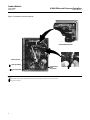
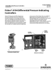
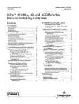
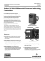
Product Bulletin
4194H Differential Pressure Controllers
34.4:4194H
May 2013
D200049X012
Fisherr 4194H Differential Pressure Indicating
Controllers
Fisher 4194H differential pressure indicating
controllers show process differential pressure and set
point on an easy‐to‐read process scale. These high
static pressure controllers sense two different
pressures and compare the difference between these
pressures with an operator‐adjusted set point. A
pneumatic signal is then delivered to a control
element to change the process differential pressure
toward the set point. 4194H controllers use a
differential pressure unit such as the Barton™ 199 for
differential pressure up to 5.2 bar (75 psi). The product
line includes proportional‐only,
proportional‐plus‐reset, and differential gap
controllers.
W5825
CONTROLLER WITH
DIFFERENTIAL PRESSURE UNIT
The controllers are also available with anti‐reset
windup, internal auto/manual station, and remote set
point adjustability (see table 1). 4194H controllers are
used throughout industries where process monitoring
and accurate measurement of differential pressure are
required.
PROCESS DIFFERENTIAL
PRESSURE INDICATOR
SET POINT
ADJUSTMENT
Features
n
n
n
Easy Maintenance—Simple design of the controller
allows fast, easy maintenance and minimal spare
parts inventory.
Easy Adjustment—Adjustments of set point and zero
and span of the process pointer, and switching
between direct and reverse action are accomplished
quickly and without special tools. Also, the set point
and proportional band can be adjusted with no
interaction between the two adjustments.
Highly Visible Display—Two red pointers on a
114 mm (4.50 inch) long white‐on‐black scale show
differential pressure and deviation from set point at
a glance. Two other gauges monitor supply and
output pressures.
www.Fisher.com
W5826‐1
SUPPLY
PRESSURE
GAUGE
OUTPUT
PRESSURE
GAUGE
INTERIOR OF CONTROLLER
n
Low Air Consumption—Relay and nozzle design
reduces steady state air consumption to as low as
0.09 m3/hr (3.5 scfh).
n
Corrosion Resistant—Thermoplastic housing
withstands a broad range of corrosive
environments. Internal constructions are available
to resist a corrosive supply pressure media.
Product Bulletin
4194H Differential Pressure Controllers
34.4:4194H
May 2013
D200049X012
Specifications
Available Configurations
Remote Set Point Pressures
J 0.2 to 1.0 bar (3 to 15 psig) or
J 0.4 to 2.0 bar (6 to 30 psig)
See table 1
Sensing Element Range (Input Signal)
Construction Materials
See table 2
See table 3
Process Scale
Controller Adjustments
J Linear, J square root, or J others on request(1)
Proportional Band: 5 to 500% of process scale range
Reset: Adjustable from 0.01 to more than 74 min per
repeat (from 100 to less than 0.0135 repeats per min)
Process Connections
Standard: 1/4 NPT internal stainless steel
(all input ranges)
Differential Gap Controllers: Adjustable from 1 to
100% of process scale range
Optional: 1/2 NPT external stainless steel
Set Point: Continuously adjustable from 0 to 100% of
the scale range
Output Signal
Controller Performance(4)
Proportional or Proportional‐Plus‐Reset Range:
J 0.2 to 1.0 bar (3 to 15 psig) or
J 0.4 to 2.0 bar (6 to 30 psig)
Repeatability: 0.4% of process scale range
Dead Band: Less than 0.2% of process scale range
Steady‐State Air Consumption(5)(6)
Differential Gap Output:
J 0 and 1.4 bar (0 and 20 psig) or
J 0 and 2.4 bar (0 and 35 psig)
0.2 to 1.0 bar (3 to 15 psig) Output:
0.09 m3/hr (3.5 scfh)
Action: Field‐reversible between J direct (increasing
sensed pressure increases output pressure) or
J reverse (increasing sensed pressure decreases
output pressure)
0.4 to 2.0 bar (6 to 30 psig) Output:
0.13 m3/hr (5.0 scfh)
Delivery Capacity(5)
0.2 to 1.0 bar (3 to 15 psig) Output:
6.4 m3/hr (240 scfh)
Supply and Output Connections
1/4 NPT internal
0.4 to 2.0 bar (6 to 30 psig ) Output:
9.4 m3/hr (350 scfh)
Supply Pressure Requirements(2)
Exhaust Capacity(5)
See table 4
0.2 to 1.0 bar (3 to 15 psig) Output:
5.0 m3/hr (186 scfh)
Supply Pressure Medium
0.4 to 2.0 bar (6 to 30 psig ) Output:
7.9 m3/hr (295 scfh)
Air or natural gas(3)
(continued)
Table of Contents
Features . . . . . . . . . . . . . . . . . . . . . . . . . . . . . . . . . . . . .
Construction Features . . . . . . . . . . . . . . . . . . . . . . . . .
Principle of Operation . . . . . . . . . . . . . . . . . . . . . . . . .
4194H Controllers . . . . . . . . . . . . . . . . . . . . . . . . . . .
Auto/Manual Option . . . . . . . . . . . . . . . . . . . . . . . . .
2
1
7
5
5
6
Installation . . . . . . . . . . . . . . . . . . . . . . . . . . . . . . . . . . 9
Ordering Information . . . . . . . . . . . . . . . . . . . . . . . . . 10
Applications . . . . . . . . . . . . . . . . . . . . . . . . . . . . . . . 10
Construction . . . . . . . . . . . . . . . . . . . . . . . . . . . . . . . 10
Product Bulletin
4194H Differential Pressure Controllers
34.4:4194H
May 2013
D200049X012
Specifications (continued)
Operative Ambient Temperature Limits(2)(7)
–40 to 70_C (–40 to 160_F)
Mounting
Controller is mounted on a pipestand
Hazardous Area Classification
Complies with the requirements of ATEX Group II
Category 2 Gas and Dust
Approximate Weight
Controller: 4.5 kg (10 lb) without the differential
pressure unit
Differential Pressure Unit: 21.5 kg (47 lb)
Housing
Designed to NEMA 3 (Weatherproof) and IEC 529
IP54 Specifications
Total Weight (controller and differential pressure
unit): 26 kg (57 lb) (with a Barton 199 Differential
Pressure Unit)
NOTE: Specialized instrument terms are defined in ANSI/ISA Standard 51.1 - Process Instrument Terminology.
1. Consult your Emerson Process Management sales office for additional information.
2. The pressure/temperature limits in this document and any applicable standard or code limitation for valve should not be exceeded.
3. This product can be used with natural gas. Natural gas should not contain more than 20 ppm of H2S.
4. With Barton 199 differential pressure unit.
5. Normal m3/hr‐‐normal cubic meters per hour (m3/hr, 0_C and 1.01325 bar, absolute). Scfh‐‐standard cubic feet per hour (ft3/hr, at 60_F and 14.7 psig).
6. Without auto/manual switch. With auto/manual switch, air consumption is 0.27 m3/hr (10 scfh).
7. Also for transportation and storage limits.
Table 1. Available Configurations
TYPE
NUMBER(1)
CONFIGURATIONS
Proportional‐
Only
Proportional‐
Plus Reset
Proportional‐Plus
Reset‐Plus‐Rate(2)
Differential
Gap
Anti‐Reset
Windup
Remote Set
Point
Internal Auto/
Manual Station
4194HA
4194HAE
4194HAM
4194HAME
X
X
X
X
‐‐‐
‐‐‐
‐‐‐
‐‐‐
‐‐‐
‐‐‐
‐‐‐
‐‐‐
‐‐‐
‐‐‐
‐‐‐
‐‐‐
‐‐‐
‐‐‐
‐‐‐
‐‐‐
‐‐‐
‐‐‐
X
X
‐‐‐
X
‐‐‐
X
4194HB
4194HBE
4194HBF
4194HBFE
4194HBM
4194HBME
4194HBFM
4194HBFME
‐‐‐
‐‐‐
‐‐‐
‐‐‐
‐‐‐
‐‐‐
‐‐‐
‐‐‐
X
X
X
X
X
X
X
X
‐‐‐
‐‐‐
‐‐‐
‐‐‐
‐‐‐
‐‐‐
‐‐‐
‐‐‐
‐‐‐
‐‐‐
‐‐‐
‐‐‐
‐‐‐
‐‐‐
‐‐‐
‐‐‐
‐‐‐
‐‐‐
X
X
‐‐‐
‐‐‐
X
X
‐‐‐
‐‐‐
‐‐‐
‐‐‐
X
X
X
X
‐‐‐
X
‐‐‐
X
‐‐‐
X
‐‐‐
X
4194HC
4194HCE
4194HCF
4194HCFE
4194HCM
4194HCME
4194HCFM
4194HCFME
‐‐‐
‐‐‐
‐‐‐
‐‐‐
‐‐‐
‐‐‐
‐‐‐
‐‐‐
‐‐‐
‐‐‐
‐‐‐
‐‐‐
‐‐‐
‐‐‐
‐‐‐
‐‐‐
X
X
X
X
X
X
X
X
‐‐‐
‐‐‐
‐‐‐
‐‐‐
‐‐‐
‐‐‐
‐‐‐
‐‐‐
‐‐‐
‐‐‐
X
X
‐‐‐
‐‐‐
X
X
‐‐‐
‐‐‐
‐‐‐
‐‐‐
X
X
X
X
‐‐‐
X
‐‐‐
X
‐‐‐
X
‐‐‐
X
4194HS
4194HSE
4914HSM
4194HSME
‐‐‐
‐‐‐
‐‐‐
‐‐‐
‐‐‐
‐‐‐
‐‐‐
‐‐‐
‐‐‐
‐‐‐
‐‐‐
‐‐‐
X
X
X
X
‐‐‐
‐‐‐
‐‐‐
‐‐‐
‐‐‐
‐‐‐
X
X
‐‐‐
X
‐‐‐
X
1. Reverse‐acting constructions are designated by an R added to the type number.
2. Consult your Emerson Process Management sales office for information on rate.
3
Product Bulletin
4194H Differential Pressure Controllers
34.4:4194H
May 2013
D200049X012
Table 2. Process Sensor (Barton 199) Ranges and Pressure Ratings
AVAILABLE DIFFERENTIAL PRESSURE UNIT OPERATING RANGES
mbar
Inch wc
0 to 50
0 to 63
0 to 125
0 to 188
0 to 250
Bar
0 to 20
0 to 25
0 to 50
0 to 75
0 to 100
Psi
0 to 1.0
0 to 3.4
0 to 5.2
0 to 15
0 to 50
0 to 75
STATIC PRESSURE OPERATING RANGE
Bar
Psig
‐ ‐ ‐(1)
‐ ‐ ‐(1)
1. Available in ranges of 0 to 70 bar (0 to 1000 psig), 0 to 172 bar (0 to 2500 psig), and 0 to 413 bar (0 to 6000 psig). Actual static pressure depends on differential pressure unit rating and
materials.
Table 3. Construction Materials
Product
4194H Controllers
Barton 199
Differential
Pressure Unit
Part
Standard Material
Optional Material
Case and cover
Polyester plastic
‐‐‐
Exterior tubing
Copper
Aluminum,stainless steel, steel, polyethylene
Exterior fittings
C36000 (brass)
Aluminum, stainless steel, steel, polyethylene
Interior tubing
Copper
S30400 (304 stainless steel)
Nozzle
S30300 (303 stainless steel)
‐‐‐
Flapper
S31600 (316 stainless steel)
‐‐‐
Relay springs
S30200 (302 stainless steel), steel
‐‐‐
Relay O‐rings
Nitrile
‐‐‐
Relay diaphragms
Nitrile
‐‐‐
Other relay metal parts
Aluminum, stainless steel
‐‐‐
C51000 (bronze)
S32100 (321 stainless steel)
Brass (wetted parts only)
Stainless steel (wetted parts only)
N09902 (nickel alloy)
‐‐‐
Feedback bellows
assembly
Supply and output
gauges
Remote set point
bellows
Mounting plates
Zinc‐plated steel
‐‐‐
Bellows
Stainless steel
‐‐‐
Housing
Steel
Stainless steel
Table 4. Supply Pressure Data
Normal Operating Supply Pressure(1)
Maximum Pressure to
Prevent Internal Damage(2)
0.2 to 1.0 or 0 and 1.4 (differential gap)
1.4
3.4
0.4 to 2.0 or 0 and 2.4 (differential gap)
2.4
3.4
3 to 15 or 0 and 20 (differential gap)
20
50
6 to 30 or 0 and 35 (differential gap)
35
50
Output Signal Range
Bar
Psig
1. If this pressure is exceeded, control stability may be impaired.
2. If this pressure is exceeded, damage to the controller may result.
4
Product Bulletin
4194H Differential Pressure Controllers
34.4:4194H
May 2013
D200049X012
Figure 1. Operational Schematic of Fisher 4194H Differential Pressure Controllers
MANUAL SET POINT
ADJUSTMENT
RESET BELLOWS (VENTED)
PROPORTIONAL
BELLOWS
REVERSE ACTION
QUADRANT
PROPORTIONAL
BAND ADJUSTMENT
PROCESS POINTER
REMOTE SET POINT
CONNECTED HERE
FEEDBACK
LINK
FEEDBACK
MOTION
INPUT ELEMENT
CONNECTED HERE
FLAPPER PIVOT
DIRECT ACTION
QUADRANT
CONNECTING
LINK
INPUT
MOTION
FLAPPER DETAIL
BEAM
OUTPUT PRESSURE
TO CONTROL DEVICE
FLAPPER
NOZZLE
SUPPLY PRESSURE
RELAY
OUTPUT PRESSURE
SUPPLY
PRESSURE
PROPORTIONAL PRESSURE
NOZZLE PRESSURE
RESET PRESSURE
PROPORTIONAL‐ONLY CONTROL
TO
PROPORTIONAL
BELLOWS
TO
NOZZLE
TO
RESET
TO
BELLOWS NOZZLE
TO
RESET
BELLOWS TO NOZZLE
OUTPUT
TO
PROPORTIONAL
BELLOWS
RESET
VALVE
TO
RESET
BELLOWS
OUTPUT
OUTPUT
RELAY
RELAY
SUPPLY
PRESSURE
RESET
VALVE
RELIEF
VALVE
PROPORTIONAL‐PLUS‐RESET CONTROL
RELAY
SUPPLY
PRESSURE
PROPORTIONAL‐PLUS‐RESET CONTROL
WITH ANTI‐RESET WINDUP
SUPPLY
PRESSURE
DIFFERENTIAL GAP CONTROL
C0742
Principle of Operation
4194H Controllers
Refer to the proportional‐only control diagram in
figure 1. The input element is connected to the
process pointer and flapper by a connecting linkage.
As the process differential pressure increases in a
direct‐acting controller, the flapper moves toward the
nozzle, restricting flow through the nozzle and
increasing nozzle pressure. When this occurs, relay
action increases the output pressure (delivery) of the
controller. Output pressure is fed back to the
proportional bellows. The action of the proportional
bellows counters the flapper movement that resulted
from the process differential pressure change, and
backs the flapper away from the nozzle. Set point
adjustment also changes the proximity of the nozzle
and flapper; however, when the set point is changed,
the nozzle moves with respect to the flapper. When
5
Product Bulletin
4194H Differential Pressure Controllers
34.4:4194H
May 2013
D200049X012
Figure 2. Schematic of Auto/Manual Option
MANUAL LOADER
AUTOMATIC
POSITION
AUTO/MANUAL
SWITCH
MANUAL
LOADER
KNOB
PLASTIC TUBE
OUTPUT PRESSURE
TO CONTROL DEVICE
METAL BALL
MANUAL
POSITION
RELAY
SUPPLY
PRESSURE
RELAY OUTPUT PRESSURE
AUTO/MANUAL
SWITCH
OUTPUT PRESSURE
TO CONTROL DEVICE
SUPPLY PRESSURE
MANUAL LOADER OUTPUT PRESSURE
48A5230‐A
A2927‐1
the controller is in the reverse‐acting mode (see
flapper detail in figure 1), an increase in process
differential pressure causes a decrease in output
pressure.
The schematic diagram (figure 1) emphasizes detail of
construction variations between control modes. Refer
to table 1 for a complete description of type number
suffixes.
In addition to the 4194HA (proportional‐only) version,
the 4194HB controller is available for
proportional‐plus‐reset control. In this controller,
output pressure is fed back to the reset bellows as well
as to the proportional bellows. Remote set point is
available on all controllers. Anti‐reset windup is
available on all controllers with reset.
Auto/Manual Option
The 4194HS controller provides differential gap
control. In this version, feedback pressure is piped
directly to the reset bellows, reinforcing the change in
flapper position rather than the counteracting it.
This construction causes the controller output to
switch from full supply pressure to zero pressure or
vice versa.
6
Controllers with the auto/manual option have piping
on the output side of the relay as shown in figure 2.
Supply pressure to the relay is also applied to the
manual loader. The manual loader, functioning as a
regulator, applies pressure to one side of the plastic
tube and to the auto/manual switch. Output pressure
from the relay registers on the other side of the plastic
tube as well as in the auto/manual switch.
When the auto/manual switch is in the MAN position,
the output of the manual loader, which is adjustable by
the manual loader knob, is channelled through the
auto/manual switch and becomes the output of the
controller. When the auto/manual switch is in the
AUTO position, the output of the relay is channelled
through the switch to become the output of the
controller.
Product Bulletin
4194H Differential Pressure Controllers
34.4:4194H
May 2013
D200049X012
Before the auto/manual switch is operated, the output
of the relay must equal the output of the manual
loader to avoid bumping the process. Adjusting the set
point varies the pressure on the left‐hand side of the
plastic tube. Adjusting the manual loader knob varies
the pressure on the right‐hand side. When the
pressures are equal, the metal ball is centered in the
tube. Pressure imbalance will force the ball to one end
of the tube where it forms a seal, blocking air flow
through the tube.
Construction Features
Remote Set Point
The capability of adjusting the set point from a remote
location is available as an option on the 4194H
controllers.
Auto/Manual Capability
An internal auto/manual station is available for smooth
bumpless transfer from automatic to manual and
manual to automatic control of the controller output.
The two‐position switch, showing either automatic or
manual mode, is clearly visible with the controller
cover closed.
Simple Relay Maintenance
A clean‐out wire provides a fast, easy means of
cleaning the relay primary orifice during service.
Pressure Protection for the Case
A rubber plug in the plastic case pops out to prevent
excessive pressure buildup inside the case, thus
preventing structural damage.
External Feedback
In controller override applications, this option
minimizes reset windup in the secondary controller
(see figure 3). This option is available only with the
two‐mode (4194HB) controllers.
Figure 3. Schematic of External Feedback Option
Easy Direct/Reverse Switching
Controller action can be switched from direct to
reverse or vice versa by simply loosening the screws on
the proportional band cover and moving the cover out
to rotate the proportional band knob to the desired
action (see figure 4).
Easy Mode Conversion
Conversion from proportional to
proportional‐plus‐reset control requires the addition
of a reset valve and two pieces of tubing. Conversion
from proportional to differential gap control requires
the addition of one piece of tubing.
TO
RESET
BELLOWS
OUTPUT
RESET
VALVE
RELAY
TO
PROPORTIONAL
BELLOWS
EXTERNAL FEEDBACK TO
OUTPUT OF HIGH OR LOW
SELECT RELAY
Anti‐Reset Windup
Anti‐reset windup is available with
proportional‐plus‐reset controllers. Relief valve may be
installed to limit reset windup in either direction.
TO
NOZZLE
SUPPLY
PRESSURE
SUPPLY PRESSURE
OUTPUT PRESSURE
NOZZLE PRESSURE
47A0975‐A
A3238‐1
RESET PRESSURE
7
Product Bulletin
34.4:4194H
May 2013
4194H Differential Pressure Controllers
D200049X012
Figure 4. Controller Construction Details
W3679
AUTO/MANUAL OPTION
CONNECTING LINK
2
ZERO ADJUSTMENT
2 SPAN ADJUSTMENT
PROPORTIONAL
BAND
ADJUSTMENT
W5826
Notes:
1 White portion of adjustment enables direct controller action; black portion enables reverse controller action.
2 For the process pointer.
8
W3439
1
Product Bulletin
4194H Differential Pressure Controllers
34.4:4194H
May 2013
D200049X012
Figure 5. Dimensions
REMOTE SET POINT
CONNECTION
260
(10.25)
330
(13.00)
TOP VIEW
1/2 NPT
(2 PLACES)
FRONT VIEW
31
(1.22)
147
(5.80)
66
(2.56)
1/4 18 NPT EXTERNAL
FEEDBACK CONNECTION,
WHEN APPLICABLE
1/4 NPT (2 HOLES)
BOTTOM VIEW
18A5903‐D
A2926‐2
1/4 NPT
(2 PLACES)
206
(8.12)
351
(13.81)
SIDE VIEW
mm
(INCH)
Installation
A 4194H controller mounts on a pipestand and must
be installed with the vent opening facing down. The
coupling is secured to the pipestand by set screws.
Figure 5 shows controller dimensions including those
necessary for installation.
9
Product Bulletin
34.4:4194H
May 2013
Ordering Information
When ordering, specify:
Application
1. Description of the service, such as throttling or
on‐off
2. Pressure range, composition, and temperature of
process fluid
3. Ambient temperature
10
4194H Differential Pressure Controllers
D200049X012
Construction
Refer to the specifications and the Construction
Features section. Carefully review each specification
and feature, indicating your choice whenever a
selection is to be made. Refer to table 1 for type
numbers; add R to any type number if reverse action is
desired.
4194H Differential Pressure Controllers
D200049X012
Product Bulletin
34.4:4194H
May 2013
11
Product Bulletin
34.4:4194H
May 2013
4194H Differential Pressure Controllers
D200049X012
Neither Emerson, Emerson Process Management, nor any of their affiliated entities assumes responsibility for the selection, use or maintenance
of any product. Responsibility for proper selection, use, and maintenance of any product remains solely with the purchaser and end user.
Fisher is a mark owned by one of the companies in the Emerson Process Management business unit of Emerson Electric Co. Emerson Process Management,
Emerson, and the Emerson logo are trademarks and service marks of Emerson Electric Co. All other marks are the property of their respective owners.
The contents of this publication are presented for informational purposes only, and while every effort has been made to ensure their accuracy, they are not
to be construed as warranties or guarantees, express or implied, regarding the products or services described herein or their use or applicability. All sales are
governed by our terms and conditions, which are available upon request. We reserve the right to modify or improve the designs or specifications of such
products at any time without notice.
Emerson Process Management
Marshalltown, Iowa 50158 USA
Sorocaba, 18087 Brazil
Chatham, Kent ME4 4QZ UK
Dubai, United Arab Emirates
Singapore 128461 Singapore
www.Fisher.com
E
121991, 2013 Fisher Controls International LLC. All rights reserved.