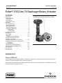
1
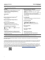
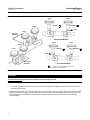
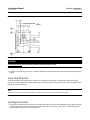
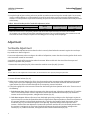
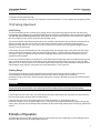
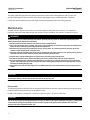
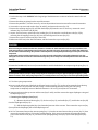
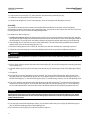
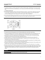
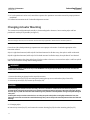
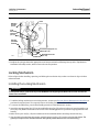
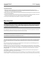
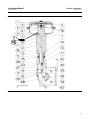
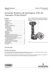
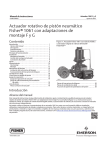
Instruction Manual 1052 Size 70 Actuators D104083X012 February 2015 Fisherr 1052 Size 70 Diaphragm Rotary Actuator Contents Introduction . . . . . . . . . . . . . . . . . . . . . . . . . . . . . . . . . 1 Scope of Manual . . . . . . . . . . . . . . . . . . . . . . . . . . . . . 1 Description . . . . . . . . . . . . . . . . . . . . . . . . . . . . . . . . . 3 Specifications . . . . . . . . . . . . . . . . . . . . . . . . . . . . . . . 3 Educational Services . . . . . . . . . . . . . . . . . . . . . . . . . 3 Installation . . . . . . . . . . . . . . . . . . . . . . . . . . . . . . . . . . 3 Actuator Mounting . . . . . . . . . . . . . . . . . . . . . . . . . . 4 Valve Flow Direction . . . . . . . . . . . . . . . . . . . . . . . . . 7 Loading Connection . . . . . . . . . . . . . . . . . . . . . . . . . . 7 Turnbuckle Adjustment . . . . . . . . . . . . . . . . . . . . . . . 8 1052 Spring Adjustment . . . . . . . . . . . . . . . . . . . . . . 9 Initial Setting . . . . . . . . . . . . . . . . . . . . . . . . . . . . 9 Stroking Range . . . . . . . . . . . . . . . . . . . . . . . . . . 9 Principle of Operation . . . . . . . . . . . . . . . . . . . . . . . . 9 Maintenance . . . . . . . . . . . . . . . . . . . . . . . . . . . . . . . . 10 Disassembly . . . . . . . . . . . . . . . . . . . . . . . . . . . . . . . 10 Assembly . . . . . . . . . . . . . . . . . . . . . . . . . . . . . . . . . . 12 Changing Actuator Mounting . . . . . . . . . . . . . . . . . 14 Top‐Mounted Handwheels and Adjustable Travel Stops . . . . . . . . . . . . . . . . . . . . . . . 15 Principle of Operation for Handwheels . . . . . . . . . 15 Handwheel Maintenance and Adjustable Travel Stop . . . . . . . . . . . . . . . . . . . . . . . . . . . . . . 16 Locking Mechanism . . . . . . . . . . . . . . . . . . . . . . . . . . 18 Installing the Locking Mechanism . . . . . . . . . . . . . 18 Operating the Locking Mechanism . . . . . . . . . . . . 19 Pipe‐Away Vent . . . . . . . . . . . . . . . . . . . . . . . . . . . . . . 21 Parts Ordering . . . . . . . . . . . . . . . . . . . . . . . . . . . . . . . 22 Parts Reference . . . . . . . . . . . . . . . . . . . . . . . . . . . . . . 22 Figure 1. Fisher Vee‐Ball™ Valve with 1052 Actuator and FIELDVUE™ DVC6200 Digital Valve Controller W8502-3 Introduction Scope of Manual This instruction manual includes installation, adjustment, maintenance, and parts ordering information for the Fisher 1052 (Size 70) pneumatic piston rotary actuator (see figure 1). This instruction manual also provides information for the optional top‐mounted handwheel, up and down travel stops, locking mechanism, and pipe‐away vent. www.Fisher.com Instruction Manual 1052 Size 70 Actuators D104083X012 February 2015 Table 1. 1052 Actuator Specifications Operation Direct Acting: Increasing loading pressure extends the diaphragm rod out of the spring barrel Service: For on‐off or throttling service with or without a positioner Actuator Sizes 70 Maximum Diaphragm Sizing Pressure(1) 3.8 bar (55 psig) Maximum Diaphragm Casing Pressure(3) 4.5 bar (65 psig) Maximum Valve Shaft Rotation Standard: 90 degrees rotation travel stop Optional: 60 or 75 degrees rotation travel stop Material Temperature Capabilities(2) NBR (Nitrile) Diaphragm: -40 to 82_C (-40 to 180_F) VMQ (Silicone) Diaphragm: -40 to 149_C (-40 to 300_F) NBR O‐Rings: -40 to 82_C (-40 to 180_F), NBR O‐rings are used in optional top‐mounted handwheel, adjustable down travel stop, and adjustable up travel stop assemblies Travel Indication Graduated disk and pointer combination located on actuator end of valve shaft Pressure Connections Standard: 1/4 NPT internal thread Optional: J1/2 or J3/4 NPT internal, and J3/4 NPT internal thread for pipe‐away vent Mounting Positions Valve Shaft Diameters, mm (Inches) J31.8 (1‐1/4), J38.1 (1‐1/2), J44.5 (1‐3/4), or J50.8 (2) Stroking Time Dependent on actuator size, rotation, spring rate, initial spring compression, and supply pressure. If stroking time is critical, consult your Emerson Process Management sales office See figure 3. Approximate Weights See table 2. Additional Specifications For casing pressure ranges and for material identification of the parts, see the Parts List 1. Use this value to determine the maximum torque output allowed. 2. The pressure/temperature limits in this manual and any applicable standard or code limitation for valve should not be exceeded. 3. This maximum casing pressure is not to be used for normal operating pressure. Its purpose is to allow for typical regulator supply settings and/or relief valve tolerances. Instructions for the control valve, positioner, accessories, and other sizes of actuators are covered in separate instruction manuals. Top‐Mounted handwheels can be applied for infrequent service as a manual handwheel actuator. Also, an adjustable up travel stop can be added to the actuator to limit its stroke in the upward direction, or an adjustable down travel stop can be added to limit actuator stroke in the downward direction. Do not install, operate, or maintain a 1052 actuator without being fully trained and qualified in valve, actuator, and accessory installation, operation, and maintenance. To avoid personal injury or property damage, it is important to carefully read, understand, and follow all the contents of this manual, including all safety cautions and warnings. If you have any questions about these instructions, contact your Emerson Process Management sales office. before proceeding. 2 Instruction Manual 1052 Size 70 Actuators D104083X012 February 2015 Figure 2. Typical 1052 Actuator Adjustable Spring Seat SPRING SPRING SEAT SPRING ADJUSTER W4742‐1 Description 1052 diaphragm rotary actuators are pneumatic spring‐return actuators for use with rotary‐shaft control valves. It can be used for on‐off service, or it can be used for throttling service when equipped with or without a valve positioner. The 1052 actuator spring is adjustable (see figure 2). Table 2. Approximate Actuator Weights SIZE 70 1052 TOP‐MOUNTED HANDWHEEL Kg Lb Kg Lb 123 272 21 47 Specifications Specifications are shown in table 1. Specifications for actuator operation, as it originally comes from the factory, are stamped on the nameplate attached to the actuator. Educational Services For information on available courses for Fisher 1052 size 70 rotary actuators, as well as a variety of other products, contact: Emerson Process Management Educational Services - Registration Phone: 1-641-754-3771 or 1-800-338-8158 E-mail: [email protected] http://www.emersonprocess.com/education Installation When an actuator and valve body are shipped together, the actuator is normally mounted on the valve. Follow the valve body instructions when installing the control valve in the pipeline, and then perform the procedures presented in the Loading Connection section. If the actuator is shipped separately or if it is necessary to mount the actuator on the valve, perform the procedures presented in the Actuator Mounting section. And, if the actuator requires a pipe‐away vent, or if a retrofit pipe‐away kit needs to be installed, refer to the Pipe‐Away Vent section. WARNING Always wear protective gloves, clothing, and eyewear when performing any installation operations. Be aware of pinching parts during installation operations. 3 Instruction Manual 1052 Size 70 Actuators D104083X012 February 2015 Check with your process or safety engineer for any additional measures that must be taken to protect against process media. If installing into an existing application, also refer to the WARNING at the beginning of the Maintenance section in this instruction manual. Table 3. Recommended Bolting Torques Description, Key Number Size NSm lbfSft Diaphragm Casing, 5 3/8‐24 27 20 Casing to spring barrel, 7 1/2‐13 102 75 Diaphragm to rod, 9 3/4‐16 102 75 Rod end bearing, 16 3/4‐16 102 75 Turnbuckle to lever, 18 3/4‐10 271 200 Spring barrel to housing, 21 5/8‐18 68 50 Housing to yoke, 23 1/2‐13 81 60 Travel stop to lever, 28 3/4‐10 271 200 Side of housing, 34 4200/PMV 1/2‐13 81 60 25 Handwheel top, 54 ‐‐‐ 34 Diaphragm head to rod/Adjustable down travel stop, 54 3/4‐16 69 51 Rod end to turnbuckle, 58 7/8‐14‐LH 163 120 Handwheel to actuator, 141 1/2‐13 81 60 CAUTION To avoid parts damage, do not use an operating pressure that exceeds the Maximum Diaphragm Casing Pressure (table 1) or produces a torque greater than the Maximum Allowable Valve Shaft Torque. Use pressure‐limiting or pressure‐relieving devices to prevent the diaphragm casing pressure from exceeding its limit. To avoid parts damage, do not stroke the actuator while cover (key 33) is off. Actuator Mounting Use the following steps to connect a valve and an actuator. Key numbers are shown in figure 8. WARNING To avoid personal injury, perform the steps in the WARNING at the beginning of the Maintenance section to isolate the control valve and actuator. 1. Unscrew cap screws and washers (keys 34 and 63), and remove the cover (key 33). 2. Refer to figure 3 for available mounting styles and positions. When mounting on a Vee‐Ball V150, V200 or V300 valve, check the valve manual to determine if it is Series B. The actuator is normally positioned vertically with the valve in a horizontal pipeline (see figure 3). 4 Instruction Manual 1052 Size 70 Actuators D104083X012 February 2015 VALVE SERIES OR DESIGN MOUNTING ACTION(1) Right‐Hand PDTC PDTO BALL/PLUG ROTATION TO CLOSE CCW(3) CCW Left‐Hand PDTC PDTO Left‐Hand (Optional)(2) PDTC PDTO VALVE SERIES OR DESIGN V250 V150, V200 & V300 CV500 and V500 A B A B A B DISK/BALL ROTATION TO CLOSE CW CW NA NA 8532, 8560 8580, and 8590 B A CCW CCW NA NA D C D C CW CW C D C D CW(4) CW NA NA C D NA NA NA NA NA NA NA NA V250 1. PDTC—Push‐down‐to‐close, and PDTO—Push‐down‐to‐open. 2. A left hand ball will be required for the NPS 3 through 12 Series B and the NPS 14 to 20, with or without attenuator. 3. CCW = counterclockwise 4. CW = clockwise WARNING To avoid personal injury or property damage, the 1052 size 70 actuator, due to its weight, must be externally supported if mounted in the horizontal position. 3. When mounting the actuators, make sure that the bushing (key 67) and valve shaft are in‐line so that the bushing will slide onto the valve shaft without damage. 4. Mount the actuator on the valve body and secure it with the valve mounting screws. The torque for 1/2 to 1‐inch shafts is 88 NSm (65 lbfSft); for 1‐1/4 to 1‐1/2 inch shafts is 136 NSm (100 lbfSft); for 1‐3/4 to 2‐inch shafts is 183 NSm (135 lbfSft). CAUTION Exceeding any torque requirement may impair the safe operation of this actuator by causing broken or damaged parts. Refer to table 3 for the bolting torque requirements. 5. Screw the left‐hand threaded locknut (key 58) onto the diaphragm rod (key 10) as far as possible. 6. Screw the turnbuckle (key 57) as far as it will go onto the actuator rod. 7. Screw the locknut (key 16) as far as it will go onto the rod end bearing (key 17). Thread this assembly completely into the turnbuckle (key 57). 8. If the lever (key 27) is attached to the rod end bearing, remove the cap screw and hex nut (keys 18 and 19). 9. If the 1052 spring adjustment has been changed, complete the Initial Setting portion of the 1052 Spring Adjustment section before proceeding. 10. Consult the appropriate valve instruction manual's Installation section for lever/valve shaft orientation marks, and slide the lever into place (see figure 4). Clamp with the cap screw (key 28). 11. Rotate the lever (key 27) to align with the rod end bearing (key 17). This connection can be aided by moving the actuator off its up travel stop with a regulated air source and adjusting the turnbuckle (key 57) slightly. 12. Apply sealant (key 77) or equivalent thread‐locking compound to the threads of the cap screw (key 18). 13. Connect the lever (key 27) and the rod end bearing (key 17) with the cap screw and hex nut (keys 18 and 19). Tighten the cap screw to the recommended bolt torque shown in table 3. 14. Note the valve position and direction of rotation. Position the travel indicator (key 37) accordingly. a. If no handwheel actuator is to be used, position the travel indicator (key 37) according to the valve position just noted. Replace the cover (key 33), and secure with washers and cap screws (keys 34 and 63). If holes in the cover and housing (key 20) do not align, temporarily loosen the cap screws (key 23), and shift the housing slightly. 5 Instruction Manual 1052 Size 70 Actuators D104083X012 February 2015 Figure 3. Mounting Styles and Positions for the 1052 Actuator STYLE A STYLE B POSITION 1 POSITION 1 1 1 STYLE D FLOW STYLE C LEFT‐HAND MOUNTING 4 2 4 2 3 3 RIGHT‐HAND MOUNTING STYLE C STYLE D STYLE B STYLE A POSITION 1 POSITION 1 1 1 FLOW 2 4 4 2 3 43A6505-A A1584-3 RIGHT‐HAND MOUNTING 3 LEFT‐HAND MOUNTING NOTES: 1 POSITION 1 IS STANDARD; POSITIONS 2 THROUGH 4 (SHOWN IN DOTTED LINES) ARE ALTERNATIVES. CAUTION To avoid parts damage, do not stroke the actuator while the cover (key 33) is off. b. If a manual handwheel actuator is to be used, refer to the separate handwheel actuator instruction manual for mounting instructions. 15. Replace the cover (key 33), and secure with cap screws and washers (keys 34 and 63). If the holes in the cover and housing (key 20) do not align, use a regulated air source to move the actuator slightly off the up travel stop. If the hole alignment cannot be obtained in this manner, temporarily loosen the cap screws (key 23), and shift the housing slightly. 6 Instruction Manual 1052 Size 70 Actuators D104083X012 February 2015 Figure 4. Lever Operating Clearance 34.9 (1.375) OPERATING CLEARANCE 1.6 (0.0625) mm (INCH) 13A6773‐A A1739‐4 CAUTION To avoid parts damage, do not stroke the actuator while the cover (key 33) is off. 16. Follow the instructions given in the Turnbuckle Adjustment section before proceeding to the Loading Connection section. Valve Flow Direction Valve construction can change the flow direction for a control valve assembly. It is important to observe the flow direction in all valve applications before installing the valve in the pipeline (see figure 3). Refer to the appropriate valve bulletin or instruction manual. Note Observe all warnings and cautions provided in the appropriate valve instruction manual Installation section. Loading Connection 1. Connect the loading pressure piping to the pressure connection in the top of the diaphragm casing. Run either pipe or tubing between the pressure connection and the instrument. If necessary, remove the 1/4 inch bushing in the pressure connection to increase connection size. 7 Instruction Manual 1052 Size 70 Actuators D104083X012 February 2015 2. Keep the length of pipe or tubing as short as possible to avoid transmission lag in the control signal. If an accessory (such as a volume booster or a valve positioner) is used, be sure that the accessory is properly connected to the actuator. If a valve positioner is part of the assembly, the pressure connection to the actuator will normally be made at the factory. Table 4. Wrench Size Required for Turnbuckle Adjustment, Inches ACTUATOR Type Size TURNBUCKLE (KEY 57) LOWER LOCKNUT (KEY 16) UPPER LOCKNUT (KEY 58) 1052 70 1‐5/16 1‐1/8 1‐5/16 3. When the control valve is completely installed and connected to the instrument, check for correct action (air‐to‐open or air‐to‐close) to match the controlling instrument. For successful operation, the actuator stem and valve shaft must move freely in response to the loading pressure change on the diaphragm. Adjustment Turnbuckle Adjustment Correct turnbuckle adjustment ensures that the valve is correctly closed when the actuator is against its travel stops. Key numbers are shown in figure 8. For accurate adjustment to the zero‐degree valve disk or ball position, remove the valve from the pipeline. Refer to the valve instruction manual for instructions. A regulated air supply will be required to stroke the actuator. Refer to table 4 for the sizes of the three open‐end wrenches required for this procedure. 1. Remove the access plate (key 59). Also remove the machine screws (key 60), if present. Note For the most accurate adjustment of the actuator, do not remove the cover (key 33) during this procedure. 2. Loosen the lower locknut (key 16). 3. Make sure the actuator housing (key 20) is clear of any tools or other instruments that could obstruct the actuator stroke path. Pressure the diaphragm casing enough to stroke the actuator down so that the left‐hand threaded upper locknut (key 58) is accessible through the access opening. Loosen the locknut. 4. Consult the appropriate valve instruction manual for determining the closed position of the valve. Then use one of the following: a. Push‐down‐to‐close—Slowly stroke the actuator to the down travel stop. Adjust the turnbuckle (key 57) until the valve is in the closed position. Lock this adjustment with the left‐hand threaded locknut (key 58). Stroke the actuator to the mid‐travel position, and tighten the locknut (key 16). b. Push‐down‐to‐open—Release all pressure from the diaphragm casing, making sure the diaphragm is against its up travel stop. Be sure that the optional handwheel is adjusted to its topmost position so that the zero position of the actuator and valve can be reached simultaneously. Check the valve position. Stroke the actuator so the turnbuckle (key 57) is accessible through the access opening. Adjust the linkage. Release pressure to the actuator, and check the new adjustment. Continue this procedure until the valve is in the closed position when the actuator is resting on its up travel stop. Stroke the actuator to the mid‐travel position, and tighten the locknut (key 16). Stroke the actuator, and tighten the left‐hand threaded locknut (key 58). 8 Instruction Manual D104083X012 1052 Size 70 Actuators February 2015 5. Replace the access plate (key 59). 6. Loosen the self‐tapping screws (key 38), adjust the travel indicator (key 37), and re‐tighten the self‐tapping screws. 1052 Spring Adjustment Initial Setting The 1052 nameplate specifies an initial spring setting, which is the initial setting adjusted into the actuator spring. Initial setting is the casing pressure at which the diaphragm and diaphragm rod begin to move away from the up travel stop with the actuator disconnected from the valve. (With the actuator connected to the valve and pressure applied to the valve, a higher pressure will be required to start actuator travel). The initial setting was selected (based upon the service conditions specified when the actuator was ordered) so that, when the actuator and valve are in service, the valve will seat properly and full travel will be obtained within a diaphragm casing range of 0 to 2.3, 0 to 2.8, or 0 to 3.8 bar (0 to 33, 0 to 40, or 0 to 55 psig) depending on specific actuator size and construction. If the actuator has been disassembled or if the spring adjustment was changed, and it is desired to match the initial setting stated on the nameplate, make sure the rod end bearing (key 17, figure 8) has been disconnected from the lever (key 27, figure 8). Adjust the spring so that the diaphragm rod just starts to travel at the spring set pressure specified on the nameplate. Be sure the rod end bearing does not hit the lever as the diaphragm and diaphragm rod move away from the up travel stop. To adjust the spring, insert a round rod into one of the holes in the lower bearing seat (key 73, figure 8). Hole diameter is 19.1 mm (3/4 inch) for size 70 actuators. Rotate the bearing seat to move it toward the casing to increase initial setting or away from the casing to decrease initial setting (keys 1 and 2, figure 8). Stroking Range The initial spring setting listed on the nameplate has been determined to be the optimum setting, and it is not recommended to make spring adjustments that will cause this value to change or be exceeded. For push‐down‐to‐open valve action, the initial spring setting is the maximum allowable to provide the maximum spring closing force. CAUTION Any increase of this setting will over‐stress the spring at full travel and may shorten the fatigue life of the spring. For push‐down‐to‐close valve action, the initial spring set has been determined to be the optimum balance between the air‐to‐close and the spring‐to‐open breakout torque. If the 1052 actuator is to be changed from one valve action to another (i.e., push‐down‐to‐close to push‐down‐to‐open), first, refer to the table for key 11 in the Parts List section to determine the proper initial spring setting; then, adjust the unit according to the procedures in the Initial Settings portion of the 1052 Spring Adjustment section. Principle of Operation The diaphragm rod moves down as loading pressure is increased on top of the diaphragm. As the loading pressure is decreased, the spring forces the diaphragm rod upward. 9 1052 Size 70 Actuators Instruction Manual February 2015 D104083X012 The spring and diaphragm have been selected to meet the requirements of the application and, in service, the actuator should produce full travel of the valve with the diaphragm pressure as indicated on the nameplate. Consult the separate positioner instruction manual for actuator principle of operation with positioner. Maintenance Actuator parts are subject to normal wear and must be inspected and replaced as necessary. The frequency of inspection and replacement depends upon the severity of service conditions. Key numbers are shown in figure 8. WARNING Avoid personal injury or property damage from sudden release of process pressure or uncontrolled movement of parts. Before performing any maintenance operations: D Do not remove the actuator from the valve while the valve is still pressurized. D Always wear protective gloves, clothing, and eyewear when performing any maintenance operations to avoid personal injury. Be aware of pinching parts during maintenance operations. D Disconnect any operating lines providing air pressure, electric power, or a control signal to the actuator. Be sure the actuator cannot suddenly open or close the valve. D Use bypass valves or completely shut off the process to isolate the valve from process pressure. Relieve process pressure from both sides of the valve. Drain the process media from both sides of the valve. D Vent the power actuator loading pressure and relieve any actuator spring precompression. D Use lock‐out procedures to be sure that the above measures stay in effect while you work on the equipment. D The valve packing box may contain process fluids that are pressurized, even when the valve has been removed from the pipeline. Process fluids may spray out under pressure when removing the packing hardware or packing rings, or when loosening the packing box pipe plug. D Check with your process or safety engineer for any additional measures that must be taken to protect against process media. CAUTION To avoid parts damage, do not stroke the actuator while cover (key 33) is off. Disassembly The following procedure describes how to completely disassemble the actuator. When inspecting and replacing parts, perform only those steps necessary to accomplish the repair. Do not, under ordinary circumstances, remove the cap screws (keys 7, 8, and 21) at this time. CAUTION Cap screw (key 18) must be disengaged from the lever (key 27) before removing the diaphragm casing (key 1). Failure to do so will allow the spring precompression to rotate the valve beyond its fully open or closed position. This could cause damage to the valve components and/or seal. 10 Instruction Manual D104083X012 1052 Size 70 Actuators February 2015 1. Perform the steps in the WARNING at the beginning of the Maintenance section to isolate the control valve and actuator. 2. Remove the tubing or piping from the top of the actuator. 3. Remove the positioner, if used. If necessary, refer to the positioner instruction manual for removal instructions. 4. Unscrew the cap screws and washers (keys 34 and 63), and remove the cover (key 33). 5. Remove the retaining ring (key 30), and slide the hub (key 29) from the cover. If necessary, remove the travel indicator (key 37) from the hub (key 29). 6. Inspect, and if necessary, replace the cover bushing (key 31). Remove the travel indicator scale (key 35) by removing the self‐tapping screws (key 36). Press the bushing out of the cover (key 33). 7. Remove the cap screw and hex nut (keys 18 and 19). 8. Make note of the lever/valve shaft orientation, and then loosen the cap screw (key 28). CAUTION When removing the actuator from the valve, do not use a hammer or similar tool to drive the lever (key 27) off the valve shaft. Driving the lever could damage internal valve parts. On some valve types, driving the lever off the shaft could move the valve disk or ball and bearings away from the centered position, causing subsequent damage to valve parts as the valve is operated. A wheel puller may be used to remove the lever. It is okay to tap the wheel puller screw lightly to loosen the lever, but hitting the screw with excessive force could also damage valve parts or disrupt the centered position of the valve disk and bearings. 9. Rotate the handwheel (if one is used) counterclockwise until the handwheel is not compressing the spring (key 11). WARNING To avoid personal injury from pre‐compressed spring force suddenly thrusting the upper diaphragm casing (key 1) away from the actuator, relieve 1052 spring compression, or carefully remove 1051 casing cap screws before proceeding further. 10. To relieve spring compression: D Insert a round rod into one of the holes in the lower bearing seat (key 73). Use the rod to rotate the lower bearing seat, and move it away from the actuator casings. Continue rotating the lower bearing seat until spring compression is completely removed. Rod hole diameter is 19.1 mm (3/4 inch) for size 70 actuators. D Unscrew and remove the cap screws and hex nuts (keys 5 and 6), and then remove the upper diaphragm casing and the diaphragm (key 3). 11. Removing the diaphragm plate (key 4): (1.) Remove the rod end bearing (key 17), the hex nut (key 16), turnbuckle (key 57), and the hex nut (key 58) from the diaphragm rod (key 10). (2.) Pull the diaphragm plate (key 4) and attached parts out of the actuator. Then remove the cap screw (key 9) to separate the diaphragm plate and the diaphragm rod. D For Size 70 actuators: Remove the actuator spring (key 11) from the actuator. Remove the cap screws (key 21), then remove the spring barrel (key 12) from the actuator housing. If it is necessary to remove the spring adjustment parts, loosen the set screw (key 75), and unscrew the spring adjusting screw (key 74) from the spring barrel (key 12). 11 1052 Size 70 Actuators Instruction Manual February 2015 D104083X012 12. Unscrew the cap screws (key 23), and remove the actuator housing assembly (key 20). 13. Unbolt the mounting yoke (key 22) from the valve. 14. Check the bushing (key 67) in the mounting yoke. Press out and replace the bushing if necessary. Assembly This procedure assumes that the actuator was completely disassembled. If the actuator was not completely disassembled, start these instructions at the appropriate step. This procedure also assumes that the valve is removed from the pipeline for ease in actuator assembly and adjustment. Key numbers are shown in figure 8. 1. Installing the spring barrel (key 12): If the spring barrel (key 12) was removed from the housing (key 20), align the spring barrel to the housing as described below to ensure that the offset hole in the base of the spring barrel will be located properly. The spring barrel need not be aligned in any particular position when placing it on the housing. 2. If the bushing (key 67) was removed, press in the new bushing. The end of the bushing should be flush with the bottom of the recess in the mounting yoke (key 22). 3. Slide the mounting yoke over the valve shaft, and secure it to the valve with the valve mounting cap screws. 4. Tighten the valve mounting cap screws to the bolting torque listed in step 6 of the Installation procedures. WARNING Exceeding any torque requirement may impair the safe operation of the actuator and lead to possible personal injury or property damage. 5. Refer to figure 4 for the desired orientation of the housing (key 20). Secure the housing to the mounting yoke with cap screws (key 23). 6. Coat with lithium grease (key 93) on the cap screw threads (key 9), and the tapered end of the diaphragm rod (key 10). 7. See figure 8. D If the adjusting screw and attached parts were removed, first clean and then lubricate the upper threads of the adjusting screw (key 74) with lithium grease (key 76) as shown in figure 8. Install the lower bearing seat (key 73), the thrust bearing (key 71), the thrust bearing races (key 72), and the spring seat (key 13) onto the adjusting screw. D First, clean and then coat the lower end of the adjusting screw with sealant (key 77) or equivalent thread‐locking compound as shown in figure 8, and install the entire assembly into the spring barrel (key 12). Let the adjusting screw stand undisturbed for at least two hours after installation to allow the thread‐locking compound to cure. CAUTION Apply lubricant to the upper threads and thread‐locking compound to the lower threads of the adjusting screw. Do not overlap the coat of lubricant with the coat of thread‐locking compound since this will adversely affect the performance quality of both substances. 8. Coat the tapered end of the diaphragm rod (key 10) and the threads of the cap screw (key 9) with lithium grease (key 76). Bolt the diaphragm plate to the diaphragm rod. 9. Be certain the travel stops (key 8) are located as shown in figure 5. 12 Instruction Manual 1052 Size 70 Actuators D104083X012 February 2015 10. Install the spring (key 11) into the spring barrel. Install the diaphragm plate and diaphragm rod into the actuator. Attach the hex nut (key 58), turnbuckle (key 57), hex nut (key 16), and rod end bearing (key 17) to the diaphragm rod. 11. Installing the diaphragm: D Install the diaphragm (key 3) and place the upper diaphragm casing (key 1) onto the lower diaphragm casing (key 2). If necessary, rotate the lower bearing seat (key 73) so that the upper diaphragm casing travel stop will not contact the diaphragm when the casing cap screws and nuts (key 5 and 6) are tightened. D Secure the upper diaphragm casing with the cap screws and hex nuts (keys 5 and 6). Be sure the warning nameplate is in place on the casing. Tighten the nuts on the cap screws to the torque value shown in table 3. Figure 5. Travel Stop Orientation 8 7 7 7 39 7 7 7 8 SIZE 70 12. Complete the Initial Setting portion of the 1052 Spring Adjustment section before proceeding. 13. Refer to the appropriate valve instruction manual for lever/valve shaft orientation marks, and slide the lever (key 27) into place; see figure 4 for correct lever operating clearance. Clamp with the cap screw (key 28, figure 8). 14. Rotate the lever (key 27) to align with the rod end bearing (key 17). This connection can be aided by carefully stroking the actuator off its up travel stop with a regulated air source. 15. Apply sealant (key 77) or equivalent thread‐locking compound to the threads of the cap screw (key 18). 16. Connect the lever (key 27) and the rod end bearing (key 17) with the cap screw and hex nut (keys 18 and 19). Tighten the nut on the cap screw (see table 3). 17. Coat the bearing surfaces of the hub (key 29), and cover (key 33) with lithium grease (key 76). Install the bushing (key 31) and hub into the cover. Secure with the retaining ring (key 30). 18. Install the travel indicator scale (key 35), and secure it with the self‐tapping screws (key 36). Then install the travel indicator (key 37), and secure it with the self‐tapping screws (key 38). 19. Note the valve disk or ball position, and direction of rotation. Position the travel indicator (key 37) accordingly. 20. Replace the cover (key 33), and secure with cap screws and washers (keys 34 and 63). If the holes in the cover and housing (key 20) do not align, use a regulated air source to move the actuator slightly off the up travel stop. If hole alignment cannot be obtained in this manner, temporarily loosen cap screws (key 23), and shift the housing slightly. CAUTION To avoid parts damage, do not stroke the actuator while cover (key 33) is off. 13 1052 Size 70 Actuators Instruction Manual February 2015 D104083X012 21. If a valve positioner is to be used, consult the separate valve positioner instruction manual for proper positioner installation. 22. Follow the instructions in the Turnbuckle Adjustment section. Changing Actuator Mounting The actuator is normally positioned vertically in a horizontal pipeline. However, four mounting styles and four positions for each style are possible (see figure 3). Note Due to its weight, the 1052, size 70 actuator must be externally supported if mounted in the horizontal position. Correct lever/valve shaft positioning is important to ensure proper valve action. Consult the appropriate valve instruction manual. Style A is right‐hand mounted, while style D is left‐hand mounted. In all other ways, the styles A and D are identical. Style B is right‐hand mounted, while style C is left‐hand mounted. In all other ways, the styles B and C are identical. Use the following procedure along with figure 8, for key number references, to convert from styles A and D to styles B and C or vice versa or to change the mounting position. WARNING To avoid personal injury, perform the steps in the WARNING at the beginning of the Maintenance section to isolate the control valve and actuator. 1. Remove the tubing or piping from the top of the actuator. 2. Remove the cover (key 33) by unscrewing and removing the cap screws and washers (keys 34 and 63). 3. Unscrew cap screw (key 18). Loosen cap screw (key 28). CAUTION When removing the actuator from the valve body, do not use a hammer or similar tool to drive the lever (key 27) or actuator off the valve shaft. Driving the lever or actuator could damage internal valve parts. On some valve types, driving the lever (key 27) could move the valve disk and bearings away from the centered position causing subsequent damage to valve parts. A wheel puller may be used to remove the lever. It is okay to tap the wheel puller screw lightly to loosen the lever, but hitting the screw with excessive force could also damage valve parts or disrupt the centered position of the valve disk and bearings. 4. If changing styles, D Unscrew cap screws (key 23), and remove the actuator housing (key 20) from the mounting yoke (key 22). 14 Instruction Manual 1052 Size 70 Actuators D104083X012 February 2015 D Rotate the housing 180 degrees, maintaining the appropriate position (1, 2, 3, or 4), and place the actuator onto the mounting yoke (key 22). 5. If changing positions, unscrew cap screws (key 23), and rotate the actuator housing to the desired position. 6. Secure actuator housing (key 20) to the mounting yoke (key 22) with cap screws (key 23). Consult table 3 for appropriate bolt torques. 7. Consult the appropriate valve instruction manual for lever/valve shaft orientation marks, and slide the lever (key 27) into place; see figure 4 for correct lever operating clearance. Clamp with the cap screw (key 28). 8. Rotate the lever (key 27) to align with the rod end bearing (key 17). This connection can be aided by stroking the actuator off its up travel stop with a regulated air source. 9. Apply sealant (key 77) or equivalent thread‐locking compound to the threads of the cap screw (key 18). 10. Connect the lever (key 27) and the rod end bearing (key 17) with the cap screw and hex nut (keys 18 and 19). Tighten cap screw to the recommended bolt torque shown in table 3. This connection can be aided by stroking the actuator from its up travel stop with a regulated air source. 11. Note the valve position and direction of rotation. Position the travel indicator (key 37) accordingly. Replace the cover (key 33), and secure it with cap screws and washers (keys 34 and 63). D If the holes in the cover and housing (key 20) do not align, use a regulated air source to move the actuator slightly off the up travel stop. D If hole alignment cannot be obtained in this manner, temporarily loosen cap screws (key 23) and shift the housing slightly. CAUTION To avoid parts damage, do not stroke the actuator while cover (key 33) is off. 12. Follow the instructions given in the Turnbuckle Adjustment section. Top‐Mounted Handwheels and Adjustable Travel Stops Principle of Operation for Handwheels Note If repeated or daily manual operation is expected or desired, the unit should be equipped with a manual handwheel actuator. Refer to the separate manual handwheel actuator instruction manual for mounting instructions. Top‐Mounted Handwheel Assembly is attached to a special upper diaphragm casing (key 1, figure 8) with cap screws (key 141, figure 9). A hex nut (key 137, figure 10) locks the handwheel in position. Turning the handwheel (key 51, figure 9) clockwise into the upper diaphragm casing forces the pusher (key 135, figure 9) against the diaphragm and diaphragm plate (keys 3 and 4, figure 8) to compress the spring (key 11, figure 8) and move the diaphragm rod downward. 15 1052 Size 70 Actuators Instruction Manual February 2015 D104083X012 Turning the handwheel counterclockwise allows the actuator spring to move the diaphragm rod upward. D If the valve is push‐down‐to‐close, full opening can be restricted by positioning the handwheel at the desired position. D If the valve is push‐down‐to‐open, full closing of the valve can be restricted by use of the handwheel. Adjustable Up Travel Stop (figure 10) limits the actuator stroke in the upward direction. To make adjustments, first relieve actuator loading pressure before removing the closing cap (key 187) as it is a pressure retaining part. Remove the closing cap (key 187). Also, for size 70 actuators, the hex nut (key 137) must be loosened. Then turn the stem (key 133) clockwise into the diaphragm case to move the actuator stem downward or counterclockwise to allow the spring to move the actuator stem upward. D If the valve has push‐down‐to‐close action, full opening can be restricted by the position of the adjustable travel stop. Or, D If the valve has push‐down‐to‐open action, full closing can be restricted by the position of the adjustable travel stop. Tighten the hex nut and replace the closing cap after adjustment. Adjustable Down Travel Stop (figure 11) limits the actuator stroke in the downward direction. To make adjustments, first relieve actuator loading pressure before removing the closing cap (key 187) as it is a pressure retaining part. Remove the closing cap (key 187). Loosen the hex jam nut (key 189) and turn the hex nut (key 63) down on the stem (key 133) to limit travel, or up on the stem to allow more travel. Lock the jam nut against the hex nut, and replace the closing cap after the adjustment has been made. Handwheel Maintenance and Adjustable Travel Stop If loading pressure seems to be leaking from either the handwheel or adjustable up stop, the O‐rings (key 138 and 139, figures 9 and 10) may need replacement. If the adjustable down stop leaks, the O‐ring (key 139, figure 11) may need replacement or possibly the closing cap (key 187, figure 10) is not tight. To tighten the closing cap, apply a good grade of thread sealant to the closing cap threads. For ease of operation, the stem threads (key 133, figures 9, 10, and 11) may need an occasional application of lithium grease (key 241). A grease fitting (key 169, figures 9 and 10) is provided for this purpose in the size 70. The size 70 may also need to have the thrust bearing (key 175, figures 9 and 10) packed with lithium grease (key 241). Travel stops for the smaller casings can be lubricated between the stem and pusher (key 135, figures 9 and 10) with lithium grease (key 241). The following disassembly procedures are separated where appropriate between the top‐mounted handwheel and adjustable up travel stop assemblies (figures 9 and 10) and the adjustable down travel stop assembly (figure 11). WARNING To avoid personal injury, perform the steps in the WARNING at the beginning of the Maintenance section to isolate the control valve and actuator. 1. Remove the tubing or pipe from the handwheel body (key 142, figures 9, 10, and 11). WARNING To avoid personal injury from the pre‐compressed spring force thrusting the upper diaphragm casing (key 1, figure 8) away from the actuator, relieve 1052 spring compression by following the instructions that are referenced in the steps below before removing the casing. 16 Instruction Manual 1052 Size 70 Actuators D104083X012 February 2015 2. Relieve all actuator spring compression by following the procedures presented in the Disassembly portion of the Maintenance section. Then, rotate either the handwheel (key 51, figure 9) or the travel stop stem (key 133, figures 10 and 11) counterclockwise until the handwheel or travel stop assembly is no longer compressing the spring. 3. Proceed as appropriate: For Adjustable Up Travel Stops: a. Remove the upper diaphragm casing (key 1, figure 8) by following steps 1, 3, 7, 9, 10, and 11 of the Disassembly portion of the Maintenance section. b. Remove the cap screws (key 141, figures 9 and 10), and separate the assembly from the upper casing. c. Loosen the locknut (key 137, figure 9), or remove the closing cap (key 187, figure 10). d. Turn the stem (key 133, figures 9 and 10) clockwise out of the valve body. On handwheel assemblies, the cotter pin and hex nut (keys 247 and 54, figure 9) will have to be removed so that the handwheel (key 51, figure 9) and locknut can be taken off the stem first. e. Remove and inspect the O‐rings (keys 138 and 139, figures 9 and 10); replace them if necessary. f. To complete disassembly: The pusher unit is held to the stem by a retaining screw (key 174, figures 9, 10 or 11). Removing the retaining screw and pusher exposes the thrust bearing (key 175, figures 9 and 10) for inspection. For Adjustable Down Travel Stops: Key numbers are shown in figure 11 unless otherwise noted. For ease of operation, the stem (key 133) threads may need an occasional application of lubricant. a. Remove the closing cap (key 187), and unscrew the jam nut and hex nut (keys 189 and 63) off the stem (key 133). b. Remove the upper diaphragm casing (key 1, figure 8) and travel stop body (key 142) by following steps 1, 3, 7, 9, 10, and 11 of the Disassembly portion of the Actuator Maintenance section. c. Unscrew cap screws (key 141), and remove the body from the diaphragm case. d. Check the condition of the O‐ring (key 139), and replace it if necessary. e. Loosen the hex nut (key 54), and then unscrew the travel stop stem (key 133) out of the actuator stem. The lower diaphragm plate (key 82) can now be removed and the rest of the actuator disassembled. 4. Reassemble by reversing the order of the disassembly steps, being sure to apply lubricant as previously mentioned and as shown by the lubrication boxes (key 241) in figures 9 and 10. For size 70 handwheels or up travel stop assemblies, coat the threads of the retaining screws (key 174, figures 9 and 10) with sealant (key 242) or equivalent thread‐locking compound. 17 Instruction Manual 1052 Size 70 Actuators D104083X012 February 2015 Figure 6. Actuator Locking Mechanism LEVER MODIFIED HOUSING (KEY 20) LEVER CAP SCREW GROOVE PIN (KEY 127) PADLOCK (CUSTOMER SUPPLIED) CAP SCREW (1 REQ'D) (KEY 129) JAM NUT (KEY 128) 34B0458‐A A6808 MOUNTING PLATE ASSY LOWER (KEY 124) LOCKING DISK 5. Readjust the spring to obtain the appropriate travel stop restriction by following the steps in the Top Mounted Handwheel Assembly section, and then return the unit to operation. Locking Mechanism Refer to figure 6 when installing, operating, and locking the mechanism. Key numbers are shown in figure 6 unless otherwise noted. Installing the Locking Mechanism WARNING To avoid personal injury, perform the steps in the WARNING at the beginning of the Maintenance section to isolate the control valve and actuator. 1. To add the locking mechanism to an existing actuator, contact your Emerson Process Management sales office. to purchase the required parts. The required parts are the locking mechanism and a modified actuator housing. 2. To remove the old housing, use the Disassembly procedures in the Maintenance section. 3. Attach the mounting plate (key 123) to the modified housing (key 20) as shown in figure 6. Attach it with the cap screw (key 129). Make sure the hole in the center of the mounting plate lines up with the large tapped hole in the housing. 4. Make sure the jam nut (key 128) is threaded onto the threaded bolt before threading it into the housing. 5. After the bolt is threaded into the housing, install the groove pin (key 127) into the end of the bolt. (Note: The groove pin will prevent the threaded bolt from being totally unthreaded from the actuator housing.) 18 Instruction Manual 1052 Size 70 Actuators D104083X012 February 2015 6. Make sure that the bolt is not threaded in so far that it will interfere with reassembly of the actuator. 7. Reassemble actuator using the Assembly procedure in the Maintenance section. 8. Make sure the actuator diaphragm rod is retracted fully. This will be the locked position of the valve. For a push‐down‐to‐close valve and actuator, the valve will be fully open when locked. For a push‐down‐to‐open valve and actuator, the valve will be fully closed when locked. 9. Screw the threaded bolt into the housing until it contacts the head on the lever cap screw (see figure 6). 10. Insert the padlock (customer supplied) to connect the mounting plate (key 123) with the lower locking disk on the mounting plate assembly (key 124). You might have to back off the lower locking disk a slight amount to line up the holes for the padlock. CAUTION The layers of the mounting plate assembly may be far enough apart that you will need to purchase a padlock with a longer loop. Do not attempt to force the layers closer to fit a small looped padlock, as property damage may result. 11. Tighten the jam nut (key 128) against the mounting plate. Operating the Locking Mechanism To Unlock the Actuator 1. Remove the padlock. Loosen the jam nut (key 128), and unscrew the threaded bolt until it is stopped by the groove pin (key 127) in the threaded bolt. CAUTION For normal operation of the actuator, the threaded bolt must be unscrewed far enough so that the actuator lever will not contact the bolt, which could lead to property damage. 2. If you are going to leave the bolt threaded into the housing, lock it by tightening the jam nut (key 128) against the mounting plate so that it cannot be screwed into the housing and interfere with normal actuator operation. 19 Instruction Manual 1052 Size 70 Actuators D104083X012 February 2015 Figure 7. Pipe Away Vent Assembly 32A9325‐F 34B4646‐B NOTE: IF ACCESSORIES ARE NOT INSTALLED ON THE MOUNTING BOSS, INSTALL CAP SCREWS (KEY 143) TO PLUG OPENINGS. A MOUNT ING BOSS IS LOCATED ON BOTH SIDES OF THE SPRING BARREL. NOTE: FOR FIELD CONVERSION OF 1052 ACTUATORS, ATTACH COVER (KEY 141) OVER THE SPRING BARREL ADJUSTMENT OPENING WITH SELF‐TAPPING SCREWS (KEY 142). USE KEY 141 AS A DRIL LING TEMPLATE. USE DRILL SIZE 2.6 mm (A #37 DRILL) (0.104‐INCH) BY 9.6 mm (0.38‐INCH) DEEP. j APPLY SEALANT ACCESSORIES MOUNTING BOSS 1052 SPRING BARREL ACCESS COVER 0 4.00 3.25 40B3945‐B NOTE: INSTALL THE HEX HEAD PLUG (KEY 140) INTO THE VENT OPEN ING LOCATED IN THE ACTUATOR HOUSING. DRILL SIZE IS 3.7 TO 4.0 BY 14.2 mm DEEP (0.145 TO 0.158 BY 0.56‐INCH). TAP SIZE IS 10‐24 UNC‐2B BY 9.6 mm (0.38‐INCH) DEEP, 4 HOLES HOUSING VENT PLUG LOCATION 34B4646‐B DRILLING AND TAPPING PATTERN ACCESS PLATE ASSEMBLY 3/4 NPT VENT CONNECTION 6.4 (0.25) 34B4646‐B TRAVEL INDICATOR NOTE: FOR FIELD CONVERSION , DRILL AND TAP HOLE PATTERN IF HOUSING HAS A NON‐METALLIC ACCESS PLATE. USE KEY 137 AS A DRILLING TEMPLATE IF DESIRED. OR, USE THE DIMENSIONS PROVIDED IN THIS FIGURE FOR DRILLING AND TAPPING. j APPLY SEALANT 34B4646‐B MOUNTING YOKE AND COVER ASSEMBLY 20 ACCESS PLATE ASSEMBLY mm (INCH) Instruction Manual D104083X012 1052 Size 70 Actuators February 2015 To Lock the Actuator 1. Make sure the actuator diaphragm rod is retracted fully. This will be the locked position of the valve. For a push‐down‐to‐close valve and actuator, the valve will be fully open when locked. For a push‐down‐to‐open valve and actuator, the valve will be fully closed when locked. 2. Make sure the jam nut (key 128) is loose. Screw the threaded bolt into the housing until it contacts the head on the lever cap screw (see figure 6). 3. Rotate the threaded bolt until one of the holes in the lower locking disk (which is welded to the bolt) is in line with the hole in the mounting plate (key 123). Tighten the jam nut against the mounting plate. 4. Lock the plate and disk together with a padlock. (The padlock is customer supplied.) Pipe‐Away Vent WARNING If a flammable or hazardous gas is being used as a supply medium, personal injury, or property damage could result from fire or explosion of accumulated gas. A remote vent pipe cannot be relied upon to vent all gases from the installed location. Provide adequate ventilation for the actuator/positioner assembly. Comply with local and regional codes, and keep the vent pipeline as short as possible with few bends. Some applications require venting of gas from the rotary actuator housing. The 3610 Series positioners vent into the actuator housing, and from there, the gas has numerous avenues of escape. Note This modification is NOT intended to be a leak‐proof or pressure‐tight design. It is intended to aid in containing the gas that vents from the positioner and allow for connection of piping to carry it away. Take care that an adequate vent pipe size is used. This is particularly important with the larger size actuators that have fast stroking speed requirements. In these situations, large quantities of gas can be vented very quickly through the positioner, and adequate pipe‐away capability must be obtained. Keep the vent piping as short as possible with few bends. Refer to the Disassembly and Assembly steps in the Maintenance section to gain access to the following parts. Key numbers are shown in figure 7 unless otherwise noted. Bushings—Remove the mounting yoke bushing (key 67), and the end plate cover bushing (key 31, figure 8). Replace them with the pipe‐away vent parts, as shown in figure 7. The mounting yoke bushing (key 132) is a two‐piece bushing with an O‐ring (key 133). The end plate cover completes the assembly with a two‐piece bushing (key 134) with an O‐ring (key 135). Travel Indicator—A gasket (key 136) is placed under the travel indicator plate. Remove the indicator plate (key 37, figure 8), install the gasket (key 136) as shown in figure 7. Access Plate Assembly—A modified metal access plate assembly (key 137) is provided with a 3/4 NPT vent connection as shown in figure 7. If the actuator had a plastic access plate, it will be necessary to drill and tap the actuator housing 21 Instruction Manual 1052 Size 70 Actuators D104083X012 February 2015 to install the machine screws (key 138) as shown in figure 7. Use the drilling and tapping pattern shown in figure 7, or use the holes in the access plate as a template to mark holes. When finished with all maintenance procedures requiring the access plate assembly (key 137) to be removed, use the sealant (key 139) provided with the kit to seal the plate in place. Housing Vent Plug—A vent is provided in the housing design. To plug this opening, the pipe‐away vent kit provides a hex pipe plug (key 140) for this opening, as shown in figure 7. Install the hex plug (key 140) into this opening and tighten it. Accessories Mounting Boss—If accessories are not installed on the mounting boss, install cap screws (key 143) to plug openings. The location to install the cap screws (key 143) is shown in figure 7. A mounting boss is located on both sides of the spring barrel (key 12, figure 8). 1052 Spring Barrel Access Cover—For field conversion of 1052 actuators, attach the cover (key 141) over the spring barrel adjustment opening with self‐tapping screws (key 142). Use key 141 as a drilling template. Drill size is 2.6 mm (A #37 drill) (0.104‐inches) by 9.6 mm (0.38‐inches) deep. Parts Ordering When corresponding with your Emerson Process Management sales office about this equipment, refer to the serial number found on the actuator nameplate (key 41, figure 9). Also, specify the complete 11‐character part number from the following parts list when ordering replacement parts. WARNING Use only genuine Fisher replacement parts. Components that are not supplied by Emerson Process Management should not, under any circumstances, be used in any Fisher valve, because they may void your warranty, might adversely affect the performance of the valve, and could cause personal injury and property damage. Parts Kits Top‐Mounted Handwheel Retrofit Kits Kit provides parts to add a top‐mounted handwheel. Kit Number 1 includes the handwheel assembly only. Kit Number 2 includes Kit Number 1 and a new upper case (key 1) that is required to mount the handwheel assembly. Kit Number 1 Key Description Size 70 22 Kit Number 2 Part Number CV8010X0052 Key Description Size 70 Part Number CV8010X0062 Instruction Manual 1052 Size 70 Actuators D104083X012 February 2015 Pipe‐Away Vent Retrofit Kit Vent‐away kits include: access plate, two‐piece bushing, two O‐rings, gasket, and the application of a sealant (sealant supplied with retrofit kit). For 1052, an additional cover plate and screws are required for the spring adjustment access. See figure 7. Pipe‐Away Vent Retrofit Kit Numbers SHAFT DIAMETER mm Inches 1052 SIZE KIT PART NUMBER 31.8 1‐1/4 70 34B4646X282 38.1 1‐1/2 70 34B4646X302 44.5 1‐3/4 70 34B4647X322 50.8 2 70 34B4647X342 Parts List Note Part numbers are shown for recommended spares only. For part numbers not shown, contact your Emerson Process Management sales office.. Common Parts (figure 8) Key Description 1 2 3* Casing, upper Diaphragm Casing, lower (steel zn pl) Diaphragm, molded (NBR/nylon) Standard w/handwheel, or w/adj up stop Size 70 w/adj down stop Size 70 VMQ/polyester Standard w/handwheel, or w/adj up stop Size 70 w/adj down stop Size 70 Diaphragm Head Screw, Cap, Hex Hd, Size 70 (24 req'd) Nut, Hex Size 70 (28 req'd) Screw, Cap, Hex Hd Size 70 (10 req'd) Stop, Travel (2 req'd) Screw, Cap, Hex Socket Diaphragm Rod Spring Spring Barrel Spring Seat Nut, Hex Bearing Rod End Screw, Cap, Hex Hd 4 5 6 7 8 9 10 11 12 13 16 17 18 *Recommended spare parts Part Number Key Description 19 20 20 21 22 23 27 28 29 30 31* Nut, Hex, Jam Housing Modified Housing Screw, Cap, Hex Hd (4 req'd) Yoke, Mounting Screw, Cap, Hex Hd (4 req'd) Lever Screw, Cap, Hex Hd Hub Ring, Retaining, Ext Bushing Size 70 12A9374X012 Cover Screw, Cap, Hex Hd w/o switches, w/ TopWorxt DXP M21GNEB, 4200, w/BZE6‐2RN or DTE6‐2RN SW, w/micro switch w/90 deg, or w/ 3710 positioner (4 req'd) w/NAMCO or LSA/LSX switches, w/ LSA/LSX sw, or w/NAMCO or LSA/LSX switch (2 req'd) Scale, Indicator Screw, Self Tapping (2 req'd) Travel Indicator Self‐Tapping Screw (2 req'd) Machine Screw (2 req'd) Plate, Cover Screw, Cap, Hex Hd (4 req'd) Nameplate Screw, Drive (4 req'd) Warning Label Turnbuckle Nut, Hex, Jam Plate, Access Washer, Plain Size 70 (2 req'd) Bushing See following table Bearing, Thrust Bearing Race (2 req'd) Bearing Seat Screw, Adjusting Lithium grease lubricant Thread locking sealant Screw, Cap 15.9 thru 50.4 mm (5/8 thru 2‐inch) Shafts (4 req'd) 33 34 2N126902202 2N130902202 2N1269X0012 2N1309X0012 See following table See following table 35 36 37 38 38 39 40 41 42 56 57 58 59 63 67* 71 72 73 74 76 77 78 Part Number 23 Instruction Manual 1052 Size 70 Actuators D104083X012 February 2015 Key Description 82 83 ‐‐‐ 144 146 Diaphragm Head, lower Plug, Protective Pipe Bushing (not shown) Warning Nameplate Spacer Part Number Top‐Mounted Handwheel (Figure 9) Handwheel Nut, Hex, Slotted Stem Plate, Pusher Nut, Hex, Jam O‐Ring, (NBR) Size 70 139* O‐ring, (NBR) Size 70 140* Pin, Groove 141 Screw, Cap, Hex Hd Size 70 (12 req'd) 142 Body 164 Body Extension 169 Grease Fitting 171 Washer, plain 174 Retaining Screw 175 Bearing, Thrust 176 Bearing Race, Thrust (2 req'd) 241 Lithium grease lubricant 242 Thread locking sealant 244 Anti‐seize lubricant 246 Spacer 247 Pin, Cotter Adjustable Down Travel Stop (Figure 11) Key Description 54 63 133 134 139* Nut, Hex Flange Nut Travel Stop Stem Washer (plain carbon steel) O‐Ring (NBR) Size 70 Screw, Cap, Hex Hd (steel zn pl) Size 70 (12 req'd) Travel Stop Body Travel Stop Cap Nut, Hex, Jam Size 70 (2 req'd) Lithium grease lubricant 141 51 54 133 135 137 138* 142 187 189 1C415706992 241 Part Number 1D269106992 1D269106992 Locking Assembly (Figure 6) 123 124 127 128 129 Mounting Plate Mounting Plate Assembly Groove Pin Jam Nut Cap Screw Pipe‐Away Vent (Figure 7) Note Complete retrofit kits are listed at the beginning of the parts list. Use this listing for individual replacement parts Adjustable Up Travel Stop (Figure 10) 133 135 137 138* Stem Plate, Pusher Nut, travel stop O‐Ring, (NBR) Size 70 139* O‐Ring, (NBR) Size 70 140* Pin, Groove 141 Screw, Cap, Hex Hd Size 70 (12 req'd) 142 Body 164 Body Extension 169 Grease Fitting 171 Spacer 174 Retaining Screw 175 Bearing, Thrust 176 Bearing Race, Thrust (2 req'd) 187 Travel Stop Cap 241 Lithium grease lubricant 242 Thread locking sealant 24 1C415706992 1D269106992 132* Lined Bushing (steel/PTFE) yoke side 31.8 mm (1‐1/4 inch) dia. shaft (2 req'd) 38.1 mm (1‐1/2 inch) dia. shaft (2 req'd) 44.5 mm (1‐3/4 inch) dia. shaft (2 req'd) 50.8 mm (2‐inch) dia. shaft (2 req'd) 133* O‐Ring (NBR) 31.8 mm (1‐1/4 inch) dia. shaft 38.1 mm (1‐1/2 inch) dia. shaft 44.5 mm (1‐3/4 inch) dia. shaft 50.8 mm (2‐inch) dia. shaft 134* Bushing (steel/PTFE) hub side 135* O‐Ring, hub side 136 Travel Indicator Gasket 137 Access Plate assembly 138 Machine screw (4 req'd) 139 Blue RTV or equivalent 140 Plug 141 Spring Barrel Cover, 1052 only (2 req'd) 142 Self‐tapping Screw Size 70 (8 req'd) 143 Cap Screw Size 70 (4 req'd) *Recommended spare parts 14B4633X012 14B4634X012 14B4635X012 G1668548112 14A6981X012 1F1153X0012 1P1676X0012 10A3800X012 Instruction Manual 1052 Size 70 Actuators D104083X012 February 2015 Figure 8. Typical 1052 Assembly A j APPLY LUBRICANT/SEALANT 58A9224‐A B2680 A 25 1052 Size 70 Actuators Figure 8. Typical 1052 Assembly (continued) 55A9224‐A SECTION A‐A FOR SIZE 70 ACTUATORS Figure 9. Handwheel Assemblies j APPLY LUBRICANT/SEALANT CV8010‐G TOP‐MOUNTED HANDWHEEL ASSEMBLY FOR SIZE 70 ACTUATOR 26 Instruction Manual D104083X012 February 2015 Instruction Manual D104083X012 1052 Size 70 Actuators February 2015 Figure 10. Adjustable Up Travel Stops j APPLY LUBRICANT/SEALANT CV8057‐E ADJUSTABLE UP TRAVEL STOP FOR SIZE 70 1052 ACTUATORS Figure 11. Adjustable Down Travel Stop 38B5654‐B A7238 27 Instruction Manual 1052 Size 70 Actuators D104083X012 February 2015 Key 11. Spring(1) for 1052 Actuators Only (Steel) INITIAL SPRING COMPRESSION Bar Psig Bar Psig Bar Psig KEY 11 SPRING PART NUMBER 0 to 2.3 0 to 33 70 0.7 10.1 0.2 3.0 1R676027082 0 to 2.8 0 to 40 70 0.7 10.1 0.2 3.3 1R676027082 0 to 3.8 0 to 55 70 0.7 10.1 0.7 10.1 1R676027082 0.2 to 2.1 3 to 30 70 0.7 10.1 0.2 3.0 1R676027082 CASING PRESSURE ACTUATOR SIZE Push‐down‐to‐open Push‐down‐to‐close 1. For more detailed ordering information concerning spring selection to obtain the torque required by the valve, consult your Emerson Process Management sales office. Keys 22 and 67*. Mounting Yoke Assembly VALVE DESIGN ACTUATOR SIZE CV500, V150, V200, V250, V300, 8510, 8532, and 8560 70 VALVE SHAFT DIAMETER mm Inches 31.8 38.1 44.5 50.8 1‐1/4 1‐1/2 1‐3/4 2 KEY 22 YOKE CAST IRON(1) 12A9799X0J2 12A9799X0K2 12A9799X0L2 12A9799X0M2 KEY 67 BUSHING, PTFE - - - - - - - - - 12A9558X012 12A9559X012 10A3848X012 12A9715X012 1. The yokes in this column are yoke‐bushing assemblies, However, the bushings are available as replacement parts. *Recommended spare parts Neither Emerson, Emerson Process Management, nor any of their affiliated entities assumes responsibility for the selection, use or maintenance of any product. Responsibility for proper selection, use, and maintenance of any product remains solely with the purchaser and end user. Fisher, Vee-Ball, FIELDVUE, and TopWorx are marks owned by one of the companies in the Emerson Process Management business unit of Emerson Electric Co. Emerson Process Management, Emerson, and the Emerson logo are trademarks and service marks of Emerson Electric Co. All other marks are the property of their respective owners. The contents of this publication are presented for informational purposes only, and while every effort has been made to ensure their accuracy, they are not to be construed as warranties or guarantees, express or implied, regarding the products or services described herein or their use or applicability. All sales are governed by our terms and conditions, which are available upon request. We reserve the right to modify or improve the designs or specifications of such products at any time without notice. Emerson Process Management Marshalltown, Iowa 50158 USA Sorocaba, 18087 Brazil Chatham, Kent ME4 4QZ UK Dubai, United Arab Emirates Singapore 128461 Singapore www.Fisher.com 28 E 2015 Fisher Controls International LLC. All rights reserved.