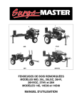
1
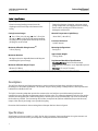
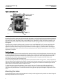
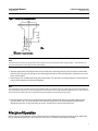
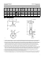
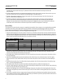
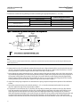
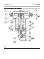
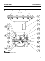
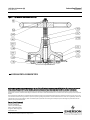
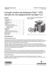
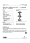
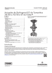
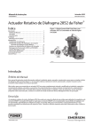
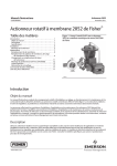
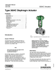
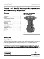
Instruction Manual
1052 Size 20 Actuator (H)
D100323X012
September 2012
Fisherr 1052 Size 20 Diaphragm Rotary Actuator
with H Mounting Adaptation
Contents
Introduction . . . . . . . . . . . . . . . . . . . . . . . . . . . . . . . . . 1
Scope of Manual . . . . . . . . . . . . . . . . . . . . . . . . . . . . . 1
Description . . . . . . . . . . . . . . . . . . . . . . . . . . . . . . . . . 2
Specifications . . . . . . . . . . . . . . . . . . . . . . . . . . . . . . . 2
Installation . . . . . . . . . . . . . . . . . . . . . . . . . . . . . . . . . . 3
Spring Compression Adjustment . . . . . . . . . . . . . . . 3
Initial Spring Compression . . . . . . . . . . . . . . . . . 3
Stroking Range . . . . . . . . . . . . . . . . . . . . . . . . . . 4
Mounting Procedure . . . . . . . . . . . . . . . . . . . . . . . . . 4
Principle of Operation . . . . . . . . . . . . . . . . . . . . . . . . 5
Maintenance . . . . . . . . . . . . . . . . . . . . . . . . . . . . . . . . . 6
Disassembly . . . . . . . . . . . . . . . . . . . . . . . . . . . . . . . . 6
Assembly . . . . . . . . . . . . . . . . . . . . . . . . . . . . . . . . . . . 8
Changing Actuator Mounting . . . . . . . . . . . . . . . . . . 9
Changing Styles . . . . . . . . . . . . . . . . . . . . . . . . . . . . . 9
Changing Positions . . . . . . . . . . . . . . . . . . . . . . . . . 11
Top Mounted Handwheel . . . . . . . . . . . . . . . . . . . . . 11
Disassembly . . . . . . . . . . . . . . . . . . . . . . . . . . . . . . . 12
Assembly . . . . . . . . . . . . . . . . . . . . . . . . . . . . . . . . . . 12
Parts Ordering . . . . . . . . . . . . . . . . . . . . . . . . . . . . . . . 12
Parts List . . . . . . . . . . . . . . . . . . . . . . . . . . . . . . . . . . . 13
Figure 1. Fisher 1052 Size 20 Actuator
with H Mounting Adaptation
W4140-1
Introduction
Scope of Manual
This instruction manual includes installation, adjustment, operation, maintenance, and parts ordering information for
the Fisher 1052 size 20 diaphragm rotary actuator with H mounting (figure 1) and the optional top-mounted
handwheel (see figure 7). Instructions for the rotary positioner and other accessories are included in separate
instruction manuals.
Do not install, operate, or maintain a 1052 actuator without being fully trained and qualified in valve, actuator, and
accessory installation, operation, and maintenance. To avoid personal injury or property damage, it is important to
carefully read, understand, and follow all the contents of this manual, including all safety cautions and warnings. If you
have any questions about these instructions, contact your Emerson Process Management sales office before
proceeding.
www.Fisher.com
Instruction Manual
1052 Size 20 Actuator (H)
September 2012
D100323X012
Table 1. Specifications
Operating Principle
Direct-Increasing loading pressure forces the
diaphragm rod from the top to the bottom of the
casing
Casing Pressure Ranges
J 0 to 1.2 bar (10 to 18 psig), J 0 to 2.3 bar (0 to
33 psig), or J 0 to 2.8 bar (0 to 40 psig) depending
on spring used for proportional control; up to 3.4 bar
(50 psig) for on-off control
Maximum Allowable Sizing Pressure(1)
3.4 bar (50 psig)
Maximum Rotation
90 degrees (travel is adjustable between 60 degrees
and 90 degrees by travel stops)
Maximum Allowable Output Torque
58 NSm (515 lbfSin)
Stroking Time
Depends on degrees of rotation, spring rate, initial
spring compression, and supply pressure. If stroking
time is critical, consult your Emerson Process
Management sales office
Material Temperature Capabilities(1)
-40 to 180_F (-40 to 82_C)
Pressure Connections
1/4 NPT internal
Mounting Configurations
See figure 5
Approximate Weight
13.6 kg (30 lb)
Top-Mounted Handwheel Specifications
Operating Principle: Can be used for manual
operation of the actuator or as an adjustable up travel
stop
Diameter: 171 mm (6.75 inches)
1. Use this value to determine the maximum torque output. The pressure-temperature limits in this manual and any applicable code or standard should not be exceeded.
Description
The 1052 size 20 spring-and-diaphragm actuator is used on small rotary shaft valves and other equipment for
throttling or on-off control applications. This actuator accepts a 3610J, 3620J, or PMV positioner, and a top-mounted
handwheel is available for the unit.
The Style H mounting adaptation permits the actuator to be used with user-provided mounting brackets and
couplings for rotary actuation of equipment other than Fisher valves. This mounting adaptation includes a flat-surface
actuator mounting plate that is drilled and tapped for attaching the user-provided bracket. Cap screws for attaching
the bracket are provided. The H mounting also includes an output shaft (with two milled flats) to provide the rotary
output, either directly or through a user-provided coupling.
Dimensional information for the mounting plate and output shaft are shown in figure 4.
Specifications
Specifications are shown in table 1 for 1052, Size 20, Style H actuators. Some specifications for a given actuator as it
originally comes from the factory are stamped on a nameplate attached to the actuator.
2
Instruction Manual
D100323X012
1052 Size 20 Actuator (H)
September 2012
Installation
WARNING
Always wear protective gloves, clothing, and eyewear when performing any maintenance operations to avoid personal
injury.
Personal injury or equipment damage caused by sudden release of pressure might result if the valve assembly is installed
where service conditions could exceed the limits given in table 1 or on the appropriate nameplates. To avoid such injury or
damage, provide a relief valve for overpressure protection as required by government or accepted industry codes and good
engineering practices.
Check with your process or safety engineer for any additional measures that must be taken to protect against process
media.
If installing into an existing application, also refer to the WARNING at the beginning of the Maintenance section in this
instruction manual.
CAUTION
To avoid parts damage, do not use an operating pressure that exceeds the Maximum Diaphragm Casing Pressure (table 1)
or produces a torque greater than the Maximum Allowable Valve Shaft Torque (see Catalog 14). Use pressure-limiting or
pressure-relieving devices to prevent the diaphragm casing pressure from exceeding its limit.
A 1/4 NPT pressure connection is located on top of the actuator. Run either NPS 1/4 pipe or 3/8-inch tubing between
the pressure connection and the instrument. Keep the length of tubing or pipe as short as possible to avoid
transmission lag in the control signal. If a positioner is used, the pressure connection to the actuator is normally made
at the factory.
When the actuator is completely installed and connected to the instrument, check it for correct action (air-to-open or
air-to-close) to match the controlling instrument. For successful operation, the actuator rod and equipment operating
shaft must move freely in response to the loading pressure change on the diaphragm.
Spring Compression Adjustment
Spring adjustment is shown in figure 2. Key numbers are shown in figure 6.
Initial Spring Compression
The 1052 nameplate specifies a SPRING INITIAL SET, which is the initial compression adjusted into the actuator spring.
Initial compression is the casing pressure at which the diaphragm (key 3) and diaphragm rod (key 10) begin to move
away from the up travel stop. The initial compression is selected (based upon the service conditions specified when
the actuator was ordered) so that when the actuator is in service on the operated equipment, the equipment closes
properly and full travel is obtained within a specified casing range.
If the actuator has been disassembled, or if the spring adjustment was changed, do NOT adjust the initial compression
to exceed the SPRING INITIAL SET value on the nameplate.
3
Instruction Manual
1052 Size 20 Actuator (H)
September 2012
D100323X012
Figure 2. Spring Adjustment
NOTCHED PORTION OF
SPRING ADJUSTER
DOWN
TRAVEL STOP
TRAVEL
INDICATOR
W6761-1
UP
TRAVEL STOP
CLAMPED
LEVER
Proper bench set of the spring can only be made when the actuator “up” travel stop has been approximately adjusted.
Insert a shaft in the actuator and adjust the “up” travel stop before establishing spring compression (since there is no
travel stop in the upper diaphragm casing). Considerable error in adjustment is certain if the above procedure is not
followed. This error can result in under travel of the actuator when the spring goes solid or excess compression has
been applied.
Adjust the spring so that the diaphragm rod just starts to travel at the SPRING INITIAL SET pressure specified on the
nameplate. To adjust the spring, remove the positioner, if one is used, or the cover. The lower part of the spring
adjuster is notched, as shown in figure 2. Using a screwdriver as shown in figure 2, rotate the notches to the right to
decrease spring compression or to the left to increase spring compression. Replace the positioner or the cover when
adjustment is complete.
Stroking Range
The SPRING INITIAL SET listed on the nameplate is the optimum setting, and spring adjustments that cause this value
to change or be exceeded are not recommended. For push-down-to-open action, the initial spring set is normally the
maximum allowable to provide the maximum spring closing force. Any increase in this setting may overstress the
spring at full travel. For push-down-to-close action, the initial spring set is the optimum balance between the
air-to-close and spring-to-open breakout torque.
If, under operating conditions, the stroking range does not match the intended casing pressure, it may be possible to
shift the stroking range by adjusting the spring to change the initial spring compression. A spring adjustment shifts the
casing pressure span and equally increases (or decreases) the casing pressure at which the actuator begins to stroke
and the pressure at which the actuator reaches full travel.
To adjust the spring, remove the positioner, if one is used, or the cover. The lower part of the spring adjuster is
notched, as shown in figure 2. Using a screwdriver as shown in figure 2, rotate the notches to the right to shift the
casing pressure span downward, or to the left to shift the casing pressure span upward. Replace the positioner or the
cover.
Mounting Procedure
Use the following steps to connect the actuator to valve body or other equipment. Key numbers are shown in figure 6.
Mounting dimensions are shown in figure 4.
4
Instruction Manual
1052 Size 20 Actuator (H)
D100323X012
September 2012
Figure 3. Center of Gravity Dimensions
125
(4.91)
58.7
(2.31)
mm
(INCH)
NOTE:
CENTER OF GRAVITY INCLUDES YOKE WEIGHT.
14B8083-A
Note
Find dimensions and center of gravity information in figures 3 and 4 and the approximate weight in table 1. This information is
required for fabrication of the proper bracket and coupling.
1. Attach an appropriate mounting bracket (not provided) to the mounting plate (key 22) in the desired orientation
with the cap screws (key 78). See figure 4 for mounting dimensions on the mounting plate. Tighten the cap screws
to the value in table 2.
2. Consult figure 5 for available mounting styles and positions. The actuator is normally positioned vertically with the
valve or other equipment in a horizontal pipeline.
Note
If the milled flats on the end of the actuator output shaft (key 87) are oriented so that the output shaft cannot accommodate the
operated equipment shaft, refer to the Changing Positions procedure of the Changing Actuator Mounting section. This procedure
describes how the output shaft can be repositioned to accommodate the operated equipment shaft.
3. Slide the actuator (with the user-provided mounting bracket attached) into the user-provided coupling on the
operated shaft. Then, secure the actuator to the operated equipment in the desired mounting position with
appropriate fasteners, such as mounting cap screws. See figure 4 for output shaft dimensions.
Principle of Operation
Refer to figure 6. The diaphragm rod (key 10) moves down as loading pressure is increased on top of the diaphragm
(key 3). As the loading pressure is decreased, the spring (key 11) forces the diaphragm rod upward.
5
1052 Size 20 Actuator (H)
September 2012
Instruction Manual
D100323X012
The spring and diaphragm are selected to meet the requirements of the application and, in service, the actuator
should produce full travel of the operated equipment with the diaphragm pressure as indicated on the nameplate.
Consult the positioner instruction manual for actuator principle of operation with positioner.
Maintenance
Actuator parts are subject to normal wear and must be inspected and replaced as necessary. The frequency of
inspection and replacement depends upon the severity of service conditions. Key numbers referenced in the following
steps are shown in figure 6.
WARNING
Avoid personal injury or property damage from sudden release of process pressure or uncontrolled movement of parts.
Before performing any maintenance operations:
D Do not remove the actuator from the valve while the valve is still pressurized.
D Always wear protective gloves, clothing, and eyewear when performing any maintenance operations to avoid personal
injury.
D Disconnect any operating lines providing air pressure, electric power, or a control signal to the actuator. Be sure the
actuator cannot suddenly open or close the valve.
D Use bypass valves or completely shut off the process to isolate the valve from process pressure. Relieve process
pressure from both sides of the valve. Drain the process media from both sides of the valve.
D Vent the power actuator loading pressure and relieve any actuator spring precompression.
D Use lock-out procedures to be sure that the above measures stay in effect while you work on the equipment.
D The valve packing box may contain process fluids that are pressurized, even when the valve has been removed from the
pipeline. Process fluids may spray out under pressure when removing the packing hardware or packing rings, or when
loosening the packing box pipe plug.
D Check with your process or safety engineer for any additional measures that must be taken to protect against process
media.
Disassembly
The following procedure describes how the actuator can be completely disassembled. When inspection or repairs are
required, disassemble only those parts necessary to accomplish the job.
1. Isolate the operated equipment from its process. Release process pressure, vent all actuator loading pressure, and
remove the tubing or pipe from the top of the actuator.
2. Remove the positioner, if applicable, or unscrew the machine screws (key 40) and remove the cover (key 39).
3. Rotate the handwheel (if one is used) counter-clockwise to be sure the handwheel is not compressing the spring
(key 11).
WARNING
Be sure to relieve spring compression before loosening the diaphragm casing cap screws and nuts (keys 5 and 6). Personal
injury can occur if spring compression forces the upper diaphragm casing (key 1) from the actuator.
6
Instruction Manual
1052 Size 20 Actuator (H)
D100323X012
E
September 2012
H
JC
K(1)
171
15.75
15.62
6.75
0.620
0.615
HC
L
S
(ACTUATOR
OUTPUT
SHAFT
DIAMETER)
T
U
V
W
Y
57.2
28.4
26.2
5/16-18 UNC
63.5
2.25
1.12
1.03
5/16-18 UNC
2.50
mm
255
57.2
184
19.1
22.2
Inches
10.06
2.25
7.25
0.75
7/8
1. Tolerance for K dimension is indicated by showing maximum and minimum dimensions.
Figure 4. Mounting Dimensions
JC (DIA)
1/4-18 NPT
1/4-18 NPT
HC
E
E
K
T
U
W
H
Y
S (DIA)
L
V
19A1461_G
4. To relieve spring compression, insert a screwdriver blade between the notches at the bottom of the spring adjuster
(key 74) as shown in figure 2. Push the screwdriver tip to the right to rotate the adjuster until a stop is reached.
5. Unscrew the cap screws (key 78) and remove the actuator from the operated equipment. Then, with the actuator at
the top of its stroke, mark the orientation of the flats on the end of the output shaft (key 87) with respect to the
actuator housing (key 20). Also, mark the orientation of the travel indictor (key 37) with respect to the travel
indictor scale (key 35). These markings are used during reassembly to allow for proper output shaft positioning.
6. Loosen the hex nut (key 145) to allow the output shaft (key 87) to slide out of the clamped lever (key 27).
7. With the housing, output shaft, travel indicator, and travel indicator scale properly marked, unscrew the cap screws
(key 23) and remove the mounting plate (key 22) and output shaft (key 87) assembly from the actuator housing. If
necessary, remove the retaining ring (key 88) and separate the output shaft (key 87) from the mounting plate.
8. Unscrew and remove the casing cap screws and hex nuts (keys 5 and 6) and the warning plate (key 56). Then,
remove the upper diaphragm casing (key 1) and the diaphragm (key 3).
9. Heat the cap screw (key 18) to 177_C (350_F) long enough for the thread locking adhesive (medium strength) (key
77) to lose its holding strength. Then, remove the cap screw (key 18). This separates the diaphragm rod/bearing
7
Instruction Manual
1052 Size 20 Actuator (H)
September 2012
D100323X012
assembly (key 10) from the lever (key 27). Remove the lever with the attached travel stops and hex nuts
(keys 8 and 86).
10. Pull the diaphragm plate (key 4) and attached diaphragm rod (key 10) out of the actuator. Remove the cap screw
(key 9) and washer (key 79) and separate the diaphragm plate and diaphragm rod.
11. Remove the actuator spring (key 11) from the actuator, lift out the spring adjuster (key 74), the spring seat
(key 13), and the thrust washer (key 71).
12. Check the condition of the bearing (key 31). If replacement of the bearing is necessary, the travel indicator
(key 37) must first be removed by removing the machine screws (key 38). Then, the hub (key 29) and travel
indicator scale (key 35) must be removed by removing the self-tapping screws or cap screws (key 36). Mark the
orientation of the travel indicator scale with respect to the actuator housing before removing it.
Assembly
This procedure assumes that the actuator is completely disassembled. If the actuator is not completely disassembled,
start these instructions at the appropriate step. Key numbers referenced in the following procedure are shown in
figure 6. Before assembling the actuator, apply lithium grease (key 76) to the threads of the spring adjuster (key 74),
to the inside of the lever (key 27), and to the equipment operating shaft.
1. Replace the bearing (key 31) if it was removed. If necessary, install the travel indicator scale (key 35) with attached
hub (key 29) and retaining ring (key 30) to the actuator housing (key 20) with the self-tapping screws or cap screws
(key 36). When installing the travel indicator scale, make sure that the markings on the scale and housing that were
made in step 10 of the Disassembly procedure are oriented correctly.
Table 2. Recommended Bolting Torques
DESCRIPTION KEY NUMBER
TORQUE
Bolt Size
LbfSft
NSm
Diaphragm Casing 5/6
3/8-24
20
27
Travel Stop 86
5/16-18
20
27
Diaphragm to rod 9
5/16-18
16
22
Rod end to lever 18
5/16-18
16
22
Housing to yoke 23
3/8-16
25
34
Clamped lever 28/145
5/16-18
20
27
2. If necessary, install the travel indicator (key 37) to the hub so that the markings on the travel indicator and travel
indicator scale that were made in step 5 of the Disassembly procedure are oriented correctly. Attach the travel
indicator to the hub with the machine screws (key 38).
3. If the diaphragm rod/bearing assembly (key 10) was removed from the actuator and separated, thread the rod into
the rod end bearing.
4. Attach the diaphragm plate (key 4) to the diaphragm rod with the cap screw and washer (keys 9 and 79). Apply
lithium grease (key 76) to the threads of the cap screw and to the portion of the rod that fits into the diaphragm
plate.
5. Install the thrust washer (key 71), followed by the spring adjuster (key 74), the spring seat (key 13) and the spring
(key 11) into the diaphragm housing.
6. Coat the threads of the cap screw (key 18) with thread locking adhesive (medium strength) (key 77).
7. Place the diaphragm plate, diaphragm rod and rod end bearing assembly into the actuator. Bolt the rod end bearing
to the lever (key 27) with the cap screw (key 18).
8. Replace the diaphragm (key 3). Position the diaphragm casing (key 1) in place on the housing (key 20). Secure the
diaphragm casing with cap screws and hex nuts (keys 5 and 6). Ensure that the warning plate (key 56) is replaced on
the casing.
9. If necessary, assemble the lever using two travel stops studs (key 8) and locking nuts (key 86) for old and new style
levers. Newer levers that can be clamped also require that you install the cap screw (key 28) and thread the lock nut
(key 145) in place, but do not tighten it at this time.
8
Instruction Manual
1052 Size 20 Actuator (H)
D100323X012
September 2012
10. Attach the output shaft (key 87) to the mounting plate (key 22) with the retaining ring (key 88). Then, with the
actuator at the top of its stroke, attach the mounting plate and output shaft assembly to the actuator housing
(key 20) with the cap screws (key 23) so that the markings that were made in step 5 of the Disassembly procedure
are oriented correctly (output shaft to actuator housing and travel indicator to travel indicator scale).
11. For newer clamping levers, torque the cap screw and nut (keys 28 and 145) on the output shaft (key 87). See
table 2 for torque values.
12. Adjust the initial spring compression as described in the spring compression adjustment procedure of the
Installation section. Remember to replace the cover and cap screws (keys 39 and 40) after performing this
procedure.
13. With the initial spring compression adjusted, slide the actuator onto the equipment operating shaft and secure it
to the mounting bracket in the desired mounting position with with mounting cap screws (key 78). Tighten the cap
screws to the value in table 2.
Changing Actuator Mounting
The actuator is normally positioned vertically in a horizontal pipeline. However, each style can be mounted in two
possible housing construction styles and four possible positions. See figure 5.
WARNING
Avoid personal injury from sudden release of process pressure or uncontrolled movement of parts. Before performing any
maintenance operations:
D Do not remove the actuator from the valve while the valve is still pressurized.
D Always wear protective gloves, clothing, and eyewear when performing any maintenance operations to avoid personal
injury.
D Disconnect any operating lines providing air pressure, electric power, or a control signal to the power actuator. Be sure
the actuator cannot suddenly open or close the valve.
D Use bypass valves or completely shut off the process to isolate the valve from process pressure. Relieve process pressure
from both sides of the valve. Drain the process media from both sides of the valve.
D Vent the power actuator loading pressure and relieve any actuator spring precompression.
D Use lock-out procedures to be sure that the above measures stay in effect while you work on the equipment.
D The valve packing box may contain process fluids that are pressurized, even when the valve has been removed from the
pipeline. Process fluids may spray out under pressure when removing the packing hardware or packing rings, or when
loosening the packing box pipe plug.
D Check with your process or safety engineer for any additional measures that must be taken to protect against process
media.
Use the following procedures along with figure 6 for key number references to convert from style A to style B or vice
versa or to change the mounting position.
Changing Styles
1. Perform steps 1 through 4 of the Disassembly portion of the Maintenance section.
2. Remove the self-tapping screws or cap screws (key 36), and then remove the hub with attached travel indicator
(keys 29 and 37) and the travel indicator scale (key 35).
3. Unscrew the cap screws (key 78) and remove the actuator assembly from its mounting bracket.
4. Unscrew the cap screws (key 23) and remove the mounting plate (key 22) and output shaft (key 87) assembly from
the actuator housing.
9
Instruction Manual
1052 Size 20 Actuator (H)
September 2012
D100323X012
5. Rotate the actuator housing 180 degrees while maintaining the appropriate position (1, 2, 3, or 4).
DESIRED ACTION OF
Actuator
Valve Body or Other Equipment
Push Down To Open(1)
Push Down To Close(2)
HOUSING CONSTRUCTION TO SPECIFY
Clockwise to Close(3)
Style A
Counterclockwise to Close(3)
Style B
Clockwise to Close(3)
Style B
Counterclockwise to Close(3)
Style A
1. This action uses the spring to close the valve or other equipment.
2. This action uses the spring to open the valve or other equipment.
3. When viewed from actuator side of valve or other equipment.
Figure 5. Actuator Housing Construction Styles and Mounting Positions
STYLE A
STYLE B
POSITION 1
POSITION 1
1
FLOW
1
4
4
2
3
2
3
RIGHT-HAND MOUNTING
NOTES:
1
DOTTED LINES INDICATE ALTERNATE MOUNTING POSITIONS 2, 3, AND 4.
14B8083-A
Note
In order to obtain a positive point of reference, position the actuator at the top of its stroke when performing the following two
steps (steps 6 and 7).
6. Position the lever (key 27) inside the actuator housing so that it is aligned with the holes at each end of the housing
(key 20). Compare the position of the lever with the position shown in figure 2. Notice that when the lever is in the
correct position to receive the output shaft, the down travel stop is nearly vertical.
7. Before sliding the output shaft into the lever, make sure that the flats that are milled on the end of the output shaft
are positioned appropriately. The flats may be positioned either parallel with or perpendicular to the spring barrel of
the actuator housing when the actuator is at the top of its stroke. With the output shaft positioned appropriately,
slide the output shaft and mounting plate assembly into the lever, and secure the mounting plate the the actuator
housing with the cap screws (key 23). Tighten the cap screws to the value in table 2.
8. Adjust the initial spring compression as described in the spring compression adjustment portion of the installation
section.
9. Secure the actuator housing in the desired position (1, 2, 3, or 4) to the mounting bracket with the cap screws
(key 78). Tighten the cap screws to the torque in table 2.
10. Separate the travel indicator (key 37) from the hub (key 29) by removing the machine screws (key 38). Slide the
hub, with attached travel indicator scale (key 35), onto the splined output shaft so that the travel indicator screw
holes align with the offset portion of the lever (where the diaphragm rod/bearing assembly (key 10) connects).
With the hub positioned properly, the travel indicator can show the correct position of the operated equipment and
can point in the direction of flow when the operated equipment is in the open position. Then, fasten the travel
indicator to the hub with the machine screws (key 38), and fasten the travel indicator scale to the actuator housing
10
Instruction Manual
1052 Size 20 Actuator (H)
D100323X012
September 2012
with the self-tapping screws or cap screws (key 36). When attaching the travel indicator scale, make certain that it is
properly aligned with the travel indicator.
11. Replace the cover and machine screws (keys 40 and 39).
Changing Positions
1. Perform steps 1 through 4 of the Disassembly portion of the Maintenance section.
2. Unscrew the cap screws (key 78) and remove the actuator assembly from its mounting
3. Unscrew the cap screws (key 78) and remove the actuator assembly from its mounting bracket.
4. Mark the orientation of the output shaft (key 87) with respect to the actuator housing (key 20). This marking is used
during re-assembly to allow for proper output shaft positioning. When the output shaft and housing are properly
marked, unscrew the cap screws (key 23) and remove the mounting plate (key 22) and output shaft (key 87)
assembly from the actuator housing.
5. Rotate the actuator housing (key 20) to the new position (1, 2, 3, or 4).
6. Position the lever inside the actuator housing so that it is aligned with the holes at each end of the housing.
Compare the position of the lever with the position shown in figure 2. Notice that when the lever is in the correct
position to receive the output shaft, the down travel stop is nearly vertical.
7. To install the output shaft into the lever, proceed as appropriate:
a. If the new actuator position is 90 degrees clockwise from the previous actuator position, align the output shaft
so that its orientation mark is located 90 degrees counterclockwise from the mark on the actuator housing.
b. If the new actuator position is 90 degrees or 180 degrees counterclockwise from the previous position, align the
output shaft so that its orientation mark is located either 90 degrees (for 90 degrees) or 180 degrees (for 180
degrees) clockwise (respectively) from the mark on the actuator housing.
8. Slide the output shaft and mounting plate assembly into the lever, and secure the mounting plate to the actuator
housing with the cap screws (key 23). Tighten the cap screws to the torque in table 2.
9. Adjust the initial spring compression as described in the spring compression adjustment portion of the Installation
section.
10. Secure the actuator housing to the mounting bracket with the cap screws (key 78). Tighten the cap screws to the
torque in table 2.
11. Note the position of the valve body or other operated equipment and direction of rotation. Remove the machine
screws (key 38) and position the travel indicator (key 37) accordingly. Replace the machine screws.
12. Replace the cover and machine screws (keys 40 and 39).
Top-Mounted Handwheel
Key numbers used in this section are shown in figure 7 except where indicated. The optional top-mounted handwheel,
shown in figure 7, can be used as a manual actuator or as an adjustable up travel stop to limit full retraction of the
diaphragm rod (key 10, figure 6).
The handwheel assembly is attached to a special upper diaphragm casing (key 1, figure 6) with cap screws (key 141). A
hex nut (key 137) locks the handwheel in position.
Turning the handwheel (key 151) clockwise into the upper casing forces the pusher plate (key 135) against the
diaphragm and diaphragm plate (keys 3 and 4, figure 6) to compress the spring (key 11, figure 6) and move the
diaphragm rod downward. Turning the handwheel counterclockwise allows the actuator spring to move the
diaphragm rod upward. If the action is push-down-to-close, full opening of the operated equipment can be restricted
11
1052 Size 20 Actuator (H)
Instruction Manual
September 2012
D100323X012
by positioning the handwheel at the desired position. If the action is push-down-to-open, full closing of the operated
equipment can be restricted by use of the handwheel.
Instructions are given below for complete disassembly and assembly required for inspection and parts replacement.
Disassembly
WARNING
To avoid personal injury from the precompressed spring force thrusting the upper diaphragm casing (key 1, figure 4) away
from the actuator, relieve spring compression before diaphragm casing bolting is loosened.
1. Remove the upper diaphragm casing (key 1, figure 6) by following steps 1 through 4, and 6 of the Disassembly
portion of the Maintenance section.
2. Remove the cotter pin, hex nut, handwheel, and hex nut (keys 247, 54, 51, and 137). Unscrew the stem (key 133)
out through the actuator end of the handwheel body (key 142).
3. Remove the cap screws (key 141), and separate the handwheel assembly from the upper casing.
4. Check the condition of the O-rings (keys 138 and 139); replace them if necessary.
5. If it is necessary to remove the pusher plate (key 135), drive out the groove pin (key 140).
Assembly
1. Before assembling, lubricate the threads of the stem (key 133) and the bearing surfaces of the stem and pusher
plate (key 135) with lithium grease (key 241).
2. If the pusher plate was removed, re-attach it to the stem, and drive in a new groove pin (key 140).
3. Apply lithium grease (key 241) to the O-rings (keys 138 and 139). With the O-rings in place, thread the stem into
the handwheel assembly.
4. Attach the handwheel assembly to the upper diaphragm casing (key 1, figure 6) with cap screws (key 141).
5. Install the hex nut, handwheel, hex nut, and cotter pin (keys 137, 51, and 247).
6. Install the diaphragm casing, making certain the warning tag is in place on the casing flange.
7. Tighten the cap screws (key 5, figure 6) evenly in a criss-cross pattern to the torque shown in table 2.
8. Adjust the initial spring compression as described in the Spring Compression Adjustment section.
Parts Ordering
Each actuator has a nameplate attached to the actuator housing and a serial number stamped on it. Always refer to
this serial number when corresponding with your Emerson Process Management sales office regarding replacement
parts or technical information.
WARNING
Use only genuine Fisher replacement parts. Components that are not supplied by Emerson Process Management should
not, under any circumstances, be used in any Fisher valve, because they may void your warranty, might adversely affect the
performance of the valve, and could cause personal injury and property damage.
12
Instruction Manual
1052 Size 20 Actuator (H)
D100323X012
September 2012
Parts Kits
Key
35
Key
Description
Part Number
---
Retrofit kit to add a top-mounted handwheel.
Kit number 1 includes the handwheel assembly only.
Kit number 2 includes kit number 1 and a new
diaphragm casing (key 1) that is required to mount
the new handwheel
Kit number 1
28A1205X012
Kit number 2
28A1205X112
Parts List
36
36
36
37
37
38
Note
Part numbers are shown for recommended spares only. For part
numbers not shown, contact your Emerson Process Management sales
office.
38
38
39
40
41
Actuator
Key
1
3*
4
5
6
8
9
10
11
13
18
20
22
23
27
28
29
30
31
Description
Part Number
Diaphragm Casing, zn pl steel
W/o handwheel
W/handwheel
Diaphragm, nitrile
26A4668X012
Diaphragm Plate, Aluminum
Cap Screw, pl steel (12 req'd)
Hex Nut, pl steel (12 req'd)
Adjustable Travel Stop, pl steel (2 req'd)
Cap Screw, pl steel
Diaphragm Rod/bearing assy, pl steel
Spring, steel
0 to 18 psig (0 to 1.2 bar) initial set
60 degrees rotation
90 degrees rotation
0 to 33 psig (0 to 2.3 bar) initial set
0 to 40 psig (0 to 2.8 bar) initial set
3 to 15 psig (0.2 to 1.0 bar) initial set
Spring Seat, cast iron
Cap Screw, pl steel
Housing, cast iron
Mounting Plate, steel
Cap Screw, zn pl steel (4 req'd)
Clamped Lever, steel
W/ or W/O switches
Positioner with 3/8-inch nominal shaft
Positioner with 1/2-inch nominal shaft
Note: If you order the old lever part number, it is
replaced with the clamped lever (key 27), nut (key 145),
and cap screw (key 28).
Cap screw, zn pl steel
Hub, Aluminum
W/o switches
W/switches
Retaining Ring, pl steel
Bearing (2 req'd)
*Recommended spare parts
42
55
55
56
71
74
76
77
78
79
86
87
88
121
145
Description
Travel Indicator Scale, stainless steel
W/o switches
W/switches
Self Tapping Screw, pl steel (2 req'd)
(none req'd w/switches)
Cap Screw, zn pl steel (for use w/GOr switch)
switch only)
One switch (3 req'd)
Two switches (2 req'd)
Cap Screw (2 req'd)
(for use w/ 304 switch)
Travel Indicator, stainless steel
Travel Indicator, stainless steel
(for use w/ 304 switch)
Machine Screw, pl steel (2 req'd)
W/o switches
W/switches
Cap Screw, pl carbon steel (2 req'd)
(for use w/GO switch only)
Cap Screw (2 req'd)
(for use w/ 304 Switch)
Cover Plate, steel (used w/o positioner)
Machine Screw, pl steel (4 req'd)
W/o positioner
Nameplate, stainless steel (specify
manufacturing location--Marshalltown,
Sherman, etc., from nameplate being
replaced)
Drive Screw, stainless steel (4 req'd)
Y602-12 Vent plastic
Vent Screen, stainless steel (for use w/GO
switch only)
Warning Plate, sticker
Thrust Washer, alloy steel
Spring Adjustor, cast iron
Lithium grease (not furnished with the actuator)
Thread locking adhesive (medium strength)
(not furnished with the actuator)
Cap Screw, zn pl steel (4 req'd)
Washer, steel
Hex Nut, zn pl steel (2 req'd)
Output Shaft, 17-4PH stainless steel
(heat treated)
Retaining Ring, pl carbon steel
Screw, Self Tap (2 req'd)
(W/o switches only)
Hex nut
Top-Mounted Handwheel
51
54
133
135
137
138*
139*
140
141
142
145
241
244
247
Handwheel, cast iron
Hex Nut, pl steel
Stem, bronze
Pusher Plate, pl steel
Hex Nut, zn pl steel
O-Ring, nitrile
O-Ring, nitrile
Groove Pin, steel
Cap Screw, pl steel (6 req'd)
Handwheel Body, cast iron
Hex Nut
Lithium grease (not furnished with the actuator)
Anti-seize lubricant (not furnished with the actuator)
Cotter Pin, stainless steel
13
1052 Size 20 Actuator (H)
September 2012
Figure 6. Actuator Assembly with H Mounting Adaptation
NOTES:
[76] APPLY LITHIUM GREASE.
49A2404-C
14
Instruction Manual
D100323X012
Instruction Manual
D100323X012
1052 Size 20 Actuator (H)
September 2012
Figure 6. Actuator Assembly with H Mounting Adaptation (continued)
NOTES:
[76] APPLY LITHIUM GREASE.
[77] APPLY THREAD LOCKING ADHESIVE (MEDIUM STRENGTH)
49A2404-C
15
1052 Size 20 Actuator (H)
September 2012
Instruction Manual
D100323X012
Figure 7. Top Mounted Handwheel Assembly
APPLY LITHIUM GREASE TO KEY 241, ANTI-SEIZE LUBRICANT TO KEY 244
28A1205-D
Neither Emerson, Emerson Process Management, nor any of their affiliated entities assumes responsibility for the selection, use or maintenance
of any product. Responsibility for proper selection, use, and maintenance of any product remains solely with the purchaser and end user.
Fisher and GO are marks owned by one of the companies in the Emerson Process Management business unit of Emerson Electric Co. Emerson Process
Management, Emerson, and the Emerson logo are trademarks and service marks of Emerson Electric Co. All other marks are the property of their respective
owners.
The contents of this publication are presented for informational purposes only, and while every effort has been made to ensure their accuracy, they are not
to be construed as warranties or guarantees, express or implied, regarding the products or services described herein or their use or applicability. All sales are
governed by our terms and conditions, which are available upon request. We reserve the right to modify or improve the designs or specifications of such
products at any time without notice.
Emerson Process Management
Marshalltown, Iowa 50158 USA
Sorocaba, 18087 Brazil
Chatham, Kent ME4 4QZ UK
Dubai, United Arab Emirates
Singapore 128461 Singapore
www.Fisher.com
16
E 1990, 2012 Fisher Controls International LLC. All rights reserved.