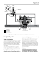
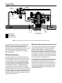
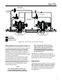
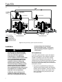
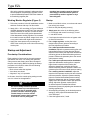
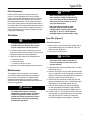
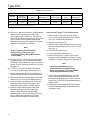
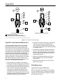
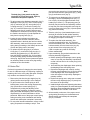
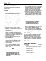
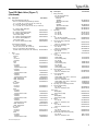
1
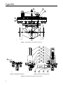
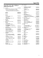
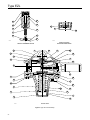
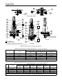
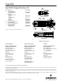
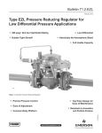
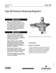
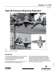
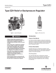
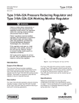
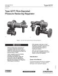
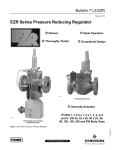
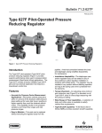
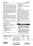
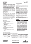
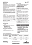
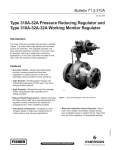
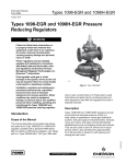
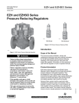
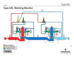
Type EZL
Instruction Manual
Form 5781
January 2015
Type EZL pressure Reducing Regulator for
Low pressure Applications
W8962
Figure 1. Type EZL Pressure Reducing Regulator
Introduction
product Description
This manual provides installation, startup,
maintenance and parts ordering information for the
Type EZL pressure reducing regulator. Information on
other equipment used with this regulator is found in
separate manuals.
Type EZL regulators are accurate pilot-operated,
pressure balanced and soft seated regulators. They
are designed for use in natural gas distribution
applications such as district regulating stations and
commercial/industrial meter sets. They provide low
differential, smooth, reliable operation, tight shutoff and
long life.
D103091X012
Scope of Manual
www.fisherregulators.com
Type EZL
Specifications
The Specifications section lists the specifications for Type EZL pressure reducing regulator. Factory specifications
for specific regulator constructions are stamped on the nameplate fastened to either the main actuator or the pilot
spring case.
Available Configuration
Type EZL: Pilot-operated pressure reducing regulator for low to high outlet pressure
Minimum Differential Pressure(1)
Body Sizes, End Connection Styles and
Pressure Ratings(1)
See Table 1
Maximum Pressures(1)
Inlet and Outlet (Design): 285 psig / 19.7 bar
Emergency (Design Casing): 285 psig / 19.7 bar
Operating Differential: 285 psid / 19.7 bar d
Outlet Pressure Ranges
See Table 2
Minimum Differential for
Full Stroke, psid / bar d
Trim, Percent
of Capacity
100
80
50
30
2 in. /
DN 50
3 and 4 in. /
DN 80 and 100
2.9 / 0.204
2.9 / 0.204
3.0 / 0.207
3.4 / 0.234
2.9 / 0.204
3.1 / 0214
3.2 / 0.221
3.5 / 0.241
Temperature Capabilities(1)
Standard Elastomers:
-20 to 180°F / -29 to 82°C
High-Temperature Elastomers:
0 to 180°F / -18 to 82°C
Options
• Prepiped Pilot Supply
• Travel Indicator
• Integral Type OS2 Slam-shut Device
1. The pressure/temperature limits in this Instruction Manual and any applicable standard or code limitation should not be exceeded.
Table 1. Main Valve Body Sizes, End Connection Styles and Body Ratings
MAIN VALVE BODY SIZE
MAIN VALVE BODY MATERIAL
WCC Steel
2, 3 and 4 in. /
DN 50, 80 and 100
Cast Iron
END CONNECTION STYLES
NPT(2) or SWE(2)
CL150 RF
CL300 RF
CL600 RF or BWE
NPT(2)
CL125B FF
CL250B RF
STRUCTURAL DESIGN RATING(1)
1500 psig / 103 bar
290 psig / 20.0 bar
750 psig / 51.7 bar
1500 psig / 103 bar
400 psig / 27.6 bar
200 psig / 13.8 bar
500 psig / 34.5 bar
1. Structural Design Rating is the rating for the main valve body. The Type EZL complete assembly is limited to 285 psig / 19.7 bar.
2. Available only on 2 in. / DN 50 body
Table 2. Outlet Pressure Ranges
pilot type
6352
6353
6354L(1)
6354M(2)
6354H
61L
61HP
161M
161EBM
1. Without diaphragm limiter.
2. With diaphragm limiter.
2
outlet control pressure range
psig
bar
2 to 10
0.14 to 0.69
3 to 40
0.21 to 2.8
35 to 125
2.4 to 8.6
85 to 200
5.9 to 13.8
175 to 220
12.1 to 15.2
200 to 285
13.8 to 19.7
0.25 to 2
0.02 to 0.14
1 to 5
0.07 to 0.34
2 to 10
0.14 to 0.69
5 to 15
0.34 to 1.0
10 to 20
0.69 to 1.4
15 to 45
1.0 to 3.1
35 to 100
2.4 to 6.9
100 to 285
6.9 to 19.7
5 to 15
0.34 to 1.0
10 to 125
0.69 to 8.6
120 to 300
8.3 to 20.7
5 to 15
0.34 to 1.0
10 to 40
0.69 to 2.8
30 to 75
2.1 to 5.2
4.8 to 9.6
70 to 140
130 to 200
9.0 to 13.8
13.8 to 24.1
200 to 350
Spring Color
Spring Part Number
Black
Yellow
Red
Blue
Blue
Green
Red
Yellow
Blue
Brown
Green
Yellow
Blue
Red
Yellow
Red
Green
White
Yellow
Black
Green
Blue
Red
14A9673X012
1E392527022
1k748527202
1l346127412
1l346127412
15a9258x012
1B886327022
1J857827022
1B886427022
1J857927142
1B886527022
1E392527022
1D387227022
1D465127142
1E392527022
1K748527202
15A9258X012
17B1260X012
17B1262X012
17B1259X012
17B1261X012
17B1263X012
17B1264X012
ype EZL with 6350 Series Pilot and
ype P590 Pilot Supply Filter
Type EZL
“C” Port
Loading Pressure
“A” Port
InLet Pressure
“D” Port
Sense
Pressure
TypE 6352 Pilot
P590 Series Pilot
Supply Filter
E0944
Inlet Pressure
Outlet Pressure
TypE EZL Main Valve
LOADING Pressure
ATMOSPHERIC Pressure
INLET PRESSURE
OUTLET PRESSURE
Figure 2. Type
EZL with Type 6352 Pilot and Type P590 Pilot Supply Filter Operational Schematic
ATMOSPHERIC
PRESSURE
LOADING PRESSURE
Principle of Operation
the actuator diaphragm escapes downstream through
the bleed restriction in the pilot.
Single-Pilot Regulator
When the gas demand in the downstream system
has been satisfied, the outlet pressure increases.
The increased pressure is transmitted through
the downstream control line and acts on the pilot
diaphragm. This pressure exceeds the pilot spring
setting and moves the diaphragm, closing the orifice.
The loading pressure acting on the main diaphragm
bleeds to the downstream system through a bleed
restriction in the pilot.
The pilot-operated Type EZL (Figure 2 or 3) uses inlet
pressure as the operating medium, which is reduced
through pilot operation to load the actuator diaphragm.
Outlet or downstream pressure opposes loading
pressure in the actuator and also opposes the pilot
control spring.
When outlet pressure drops below the setting of
the pilot control spring, pilot control spring force on
the pilot diaphragm thus opens the pilot valve plug,
providing additional loading pressure to the actuator
diaphragm. This diaphragm loading pressure opens
the main valve plug, supplying the required flow to the
downstream system. Any excess loading pressure on
Adjustment
The adjustment of the regulator is performed by
means of the pilot adjusting screw, which varies
the compression of the control spring. Adjustment
3
Type EZL
January 2008
Type EZL with Type 61L Pilot
Type EZL
Sense
Pressure
Inlet
Pressure
Loading
Pressure
P590 Series Pilot
Supply Filter
E0959
TypE 61L Pilot
E0959
TypE EZL Main Valve
Inlet Pressure
Outlet Pressure
LOADING Pressure
INLET PRESSURE
ATMOSPHERIC Pressure
OUTLET PRESSURE
LOADING PRESSURE
ATMOSPHERIC PRESSURE
INLET PRESSURE
OUTLET PRESSURE
LOADING PRESSURE
ATMOSPHERIC PRESSURE
Figure 3. Type EZL with Type 61L Pilot and Type P590 Pilot Supply Filter Operational Schematic
is performed while the regulator is in operation with
the aid of a pressure gauge to monitor downstream
pressure. The shutoff valve downstream of the
regulator must not be completely closed; it is necessary
that a small quantity of gas flows downstream to
allow the outlet side to vent, when it is necessary to
lower the pressure.
Monitoring Systems
Monitoring regulation is overpressure protection by
containment, therefore, there is no relief valve to vent
to the atmosphere. When the working regulator fails
to control the pressure, a monitor regulator installed
in series, which has been sensing the downstream
and control pressure, goes into operation to maintain
the downstream pressure at a slightly higher than
normal pressure. During an overpressure situation,
monitoring keeps the customer on line. Also, testing is
relatively easy and safe. To perform a periodic test on a
monitoring regulator, increase the outlet set pressure of
the working regulator and watch the outlet pressure to
determine if the monitoring regulator takes over at the
appropriate outlet pressure.
4
Wide-Open Monitoring Systems (Figure 4)
There are two types of wide-open monitoring systems:
upstream and downstream. The difference between
upstream and downstream monitoring is that the
functions of the regulators are reversed. Systems can
be changed from upstream to downstream monitoring
and vice-versa, by simply reversing the setpoints of the
two regulators. The decision to use either an upstream
or downstream monitoring system is largely a matter of
personal preference or company policy.
In normal operation of a wide-open configuration, the
working regulator controls the system’s outlet pressure.
With a higher outlet pressure setting, the monitor
regulator senses a pressure lower than its setpoint and
tries to increase outlet pressure by going wide-open.
If the working regulator fails, the monitoring regulator
assumes control and holds the outlet pressure at its
outlet pressure setting.
TypeEZL
EZL
Type
Type EZL Upstream or Downstream Wide-Open Monitor
January 2008
Type 67C Pilot
Supply Regulator
P590 Series
Pilot Supply
Filter
TypE 6352 Pilot
P590 Series Pilot
Supply Filter
E0948
TypE 6352 Pilot
E0948
INLET PRESSURE
OUTLET
InletPRESSURE
Pressure
LOADING
PRESSURE
Outlet
Pressure
INTERMEDIATE PRESSURE
LOADING Pressure
ATMOSPHERIC
PRESSURE
INTERMEDIATE Pressure
TypE EZL Main Valve
INLET PRESSURE
OUTLET PRESSURE
LOADING PRESSURE
INTERMEDIATE PRESSURE
ATMOSPHERIC PRESSURE
TypE EZL Main Valve
Atmospheric Pressure
Figure 4. Wide-Open Monitoring System Operational Schematic
Working Monitoring Regulators (Figure 5)
In a working monitoring system, the upstream regulator
requires two pilots and it is always the monitoring
regulator. The additional pilot permits the monitoring
regulator to act as a series regulator to control an
intermediate pressure during normal operation. In this
way, both units are always operating and can be easily
checked for proper operation.
In normal operation, the working regulator controls
the outlet pressure of the system. The monitoring
regulator’s working pilot controls the intermediate
pressure and the monitoring pilot senses the system’s
outlet pressure. If the working regulator fails, the
monitoring pilot will sense the increase in outlet
pressure and take control.
Note
The working regulator must be rated
for the maximum allowable operating
pressure of the system because this will
be its inlet pressure if the monitoring
regulator fails. Also, the outlet pressure
rating of the monitoring pilot and any
other components that are exposed to
the intermediate pressure must be rated
for full inlet pressure.
Working monitor installations require a Type EZL
main valve with a working pilot and a monitoring pilot
for the upstream regulator and a Type EZL with the
appropriate pilot for the downstream regulator.
Adjustment
Adjusting the monitor regulator is similar to adjusting
the main regulator. Monitor setpoints are set slightly
higher than the main regulator. However, the value
of this difference cannot be determined in advance,
as it depends on the particular characteristics of
each application.
5
Type EZL
Type EZL
January 2008
Type EZL Working Monitor
P590 Series
Pilot Supply
Filter
TypE 161EBM
Monitor Pilot
TypE 6352 Pilot
TypE 6352 Pilot
E0946
P590 Series Pilot
Supply Filter
INLET PRESSURE
TypE EZL Main Valve
OUTLET PRESSURE
Inlet Pressure
LOADING
PRESSURE
Outlet Pressure
INTERMEDIATE
PRESSURE
ATMOSPHERIC
PRESSURE
LOADING Pressure
E0946
TypE EZL Main Valve
INTERMEDIATE Pressure
Atmospheric Pressure
Figure 5. Working Monitoring System Operational Schematic
Installation
!
Warning
Personal injury or equipment damage,
due to bursting of pressure-containing
parts may result if this regulator is
overpressured or is installed where
service conditions could exceed the limits
given in the Specification section and
on the appropriate nameplate or where
conditions exceed any rating of the
adjacent piping or piping connections.
To avoid such injury or damage, provide
pressure-relieving or pressure-limiting
devices to prevent service conditions
from exceeding those limits. Also, be sure
the installation is in compliance with all
applicable codes and regulations.
Additionally, physical damage to the
regulator could break the pilot off the
main valve, causing personal injury and
6
property damage due to bursting of
pressure-containing parts. To avoid such
injury and damage, install the regulator in
a safe location.
All Installations
A Type EZL regulator bleeds no gas to atmosphere
during normal operation, thus making the regulator
suitable for installation in pits and other enclosed
locations without elaborate venting systems. This
regulator also can be installed in pits subject to flooding
by venting the pilot spring case above the expected
flood level so that the pilot setting can be referenced to
atmospheric pressure.
1. Only personnel qualified through training and
experience should install, operate and maintain a
regulator. Before installation, make sure that there
is no damage to or debris in the regulator. Also,
make sure that all tubing and piping are clean
and unobstructed.
Type EZL
Note
When upgrading Fisher® control valves,
such as Types ET, ED and ES make sure
the body is in the flow up direction.
2. Install the regulator so that the flow arrow on the
main valve matches the flow direction of process
fluid through the regulator.
3. Apply pipe comlb to the external pipeline threads
before installing a regulator with threaded end
connections. Use gaskets between pipeline and
regulator flanges when installing a regulator with
flanged end connections. When installing buttweld
end connections, remove trim before welding and
make sure to use approved welding practices.
Use approved piping procedures when installing
the regulator.
!
Warning
A regulator may vent some gas to the
atmosphere. In hazardous or flammable
gas service, vented gas may accumulate,
causing personal injury, death or
property damage due to bursting of
pressure-retaining parts. Vent a regulator
in hazardous gas service to a remote,
safe location away from air intakes or
any hazardous location. The vent line or
stack opening must be protected against
condensation or clogging.
4. Pilots have a 1/4 in. NPT vent connection in the
spring case. To remotely vent gas from the spring
case, remove the screened vent and connect
1/4 in. / 6.4 mm piping or tubing to the spring case
connection. The piping or tubing should vent to
a safe location, have as few elbows as possible
and have a screened vent on its exhaust. Install
the regulator and any remote vent piping or tubing
so that the vent is protected from condensation,
freezing or substances that may clog it.
caution
To avoid freezeup because of pressure
drop and moisture in the gas, use antifreeze practices, such as heating the
supply gas or adding a de-icing agent to
the supply gas.
5. Run a 3/8 in. / 9.5 mm outer diameter or larger pilot
supply line from the upstream pipeline to the filter
inlet as shown in Figure 3, bushing the line down
to fit the 1/4 in. threaded NPT filter connection.
Do not make the upstream pipeline connection in
a turbulent area, such as near a nipple, swage or
elbow. If the maximum pilot inlet pressure could
exceed the pilot rating, install a separate reducing
regulator in the pilot supply line. Install a hand valve
in the pilot supply line and provide vent valves
to properly isolate and relieve the pressure from
the regulator.
6. Attach a 1/2 in. / 12 mm piping or tubing
downstream control line to the 1/2 in. threaded NPT
control line connection on the actuator casings.
Connect the other end of the control line to the
pipeline downstream of the regulator. Do not attach
the control line near any elbow, swage, block valve
or any other location that might cause turbulence.
Install a full port ball valve in the control line to
shutoff the control pressure when using the bypass.
7. If a quick acting solenoid is to be installed
downstream of a regulator, the regulator and
solenoid should be located as far apart as practical.
This will maximize the gas piping volume between
the regulator and solenoid and improve the
regulator response to quick changing flow rates.
8. Consult the appropriate instruction manual for
installation of an optional pneumatic or electric
remote control drive unit. For optional remote
pneumatic loading of a 6350 or 61 Series pilot,
make the loading piping connections to the
1/4 in. NPT vent connection.
Wide-Open Monitor Regulator (Figure 4)
1. Follow the procedures in the All Installations
section and then continue with step 2 of
this section.
2. Connect the control line of the wide-open
monitoring regulator to the downstream piping
near the working regulator control line connection.
During normal operation, the wide-open regulator
stands wide-open with the pressure reduction
being taken across the working regulator. Only
in case of working regulator failure does the
wide-open monitoring regulator take control at its
slightly higher setting.
Regardless of which regulator is used as the monitor,
it should be equipped with a pilot supply regulator
set to limit the pilot supply pressure to 10 to 15 psig /
0.69 to 1.0 bar above control pressure. Since the
7
Type EZL
pilot on the monitoring regulator is wide-open during
normal operation, the pilot supply regulator is used
to prevent differential pressure relief valve chatter on
the monitoring regulator pilot.
Working Monitor Regulator (Figure 5)
Startup
1. Follow the procedure in the All Installations section
and then continue with step 2 of this section.
1. Make sure all block valves, vent valves and control
line valve(s) are closed.
2. Attach 3/8 in. / 9.5 mm tubing (for Types 161M and
161EBM) downstream control line to the control line
(sense) connection on the pilot. Connect the other
end of the control line to the pipeline downstream
of the downstream working regulator. Do not attach
the control line near any elbow, swage, block valve
or any other location that might cause turbulence.
2. Back out the pilot adjusting screw(s).
3. Apply pilot sense pressure by connecting the
outlet of the monitor pilot to the inlet of the working
monitor pilot.
5. For a single regulator, set the pilot to the
desired outlet (control) pressure according to
the Pilot Adjustment procedure.
For a wide-open downstream monitor
installation, adjust the upstream working pilot until
intermediate pressure is higher than the desired
setpoint of the monitor pilot. Adjust the downstream
monitoring pilot to the desired monitoring takeover
pressure. Reduce the upstream pilot to the normal
outlet pressure setting.
For a wide-open upstream monitor installation,
adjust the downstream working pilot to a setpoint
higher than the setpoint of the monitor pilot.
Adjust the downstream monitoring pilot to the
desired monitoring takeover pressure. Reduce the
upstream pilot to the normal outlet pressure setting.
For a working monitor installation, adjust the
setpoint of the upstream monitor pilot to the desired
maximum pressure. Adjust the upstream working
pilot to the desired intermediate pressure setting.
Adjust the downstream pilot to a pressure setting
slightly above the upstream monitor pilot pressure
setting. Adjust the upstream monitor pilot to
its desired setpoint. Establish final desired
downstream pressure by adjusting the downstream
working regulator pilot.
Startup and Adjustment
Pre-startup Considerations
Each regulator is factory-set for the outlet pressure
specified on the order. If no setting was specified,
outlet pressure was factory-set at the mid-range of
the pilot control spring. Before beginning the startup
procedure in this section, make sure the following
conditions are in effect:
• Block valves isolate the regulator
• Vent valves are closed
• A bypass, if any, is in operation
In all cases, check the control spring setting to make
sure it is correct for the application.
caution
Be sure to slowly introduce pressure
into the system to prevent downstream
overpressure due to potential rapid
pressure increase. Pressure gauges
should always be used to monitor
downstream pressure during startup.
Procedures used in putting this
8
regulator into operation must be planned
accordingly if the downstream system is
pressurized by another regulator or by a
manual bypass.
3. Slowly open the valves in the following order:
a. Pilot supply and control line valve(s), if used.
b. Inlet block valves.
4. Crack open the outlet block valve or bypass valve
to allow minimum flow.
6. After adjusting the pilot(s) to the desired pressure
setting(s), slowly open the downstream block
valve wide-open.
7. Close the bypass valve, if used.
Type EZL
Pilot Adjustment
caution
Remove closing cap, if necessary. Loosen the
locknut. Turn the adjusting screw into the spring
case to increase the downstream pressure. Turn the
adjusting screw out of the spring case to decrease
the downstream pressure. Use a pressure gauge to
monitor the outlet pressure until the desired pressure
is reached. When the required downstream pressure is
maintained for several minutes, tighten the locknut to
lock the adjusting screw in position. Replace the pilot
closing cap, if necessary.
Shutdown
caution
If the pilot bleed control line pressure is
shutdown first, the downstream system
may be subjected to full inlet pressure.
1. If the pilot setting must be disturbed, be sure to
keep some tension on the spring. This will prevent
trapping inlet pressure during blow down.
2. Slowly close the valves in the following order:
a. Inlet block valve
b. Outlet block valve
c. Control line valve(s), if used.
3. Open the vent valves to depressurize the system.
Maintenance
The regulator parts are subject to normal wear
and must be inspected periodically and replaced
as necessary. The frequency of inspection and
replacement depends on the severity of service
conditions and on applicable federal, state and local
codes and regulations.
!
Warning
To avoid personal injury or property
damage from sudden release of pressure,
isolate the regulator from the pressure
system and release all pressure from the
pilot and main valve before performing
maintenance operations.
When disassembling the upper and
lower actuator, always remove the long
cap screws (key 39) last to allow spring
tension force to be released in a slow
and controlled manner.
Use proper lifting techniques, when
lifting the upper and lower actuator
casings (keys 11 and 5) off the Type EZL
body (key 1). The 2 in. / DN 50 actuator
assembly weighs more than 40 lbs / 18 kg.
Type EZL (Figure 7)
Seat Maintenance
1. Make a mark on the lower actuator casing (key 5),
intermediate flange (key 25) and body (key 1) to
indicate proper alignment.
2. Remove stud nuts (key 26).
caution
Use proper care in moving actuator to
ensure no damage occurs to the pins or
actuator casings.
3. Carefully lift the actuator assembly (keys 11 and 5)
off the body (key 1).
4. Remove O-ring (key 34) from lower actuator casing
(key 5). Inspect the O-ring for damage or wear and
replace if necessary. Lightly lubricate O-ring before
placing on lower actuator casing (key 5).
5. Remove the hex socket cap screws (key 33) and
spring lock washers (key 32). Lift off the disk holder
assembly (key 30) and disk retainer (key 31).
6. Remove the O-ring (key 29). Inspect for damage
or wear and replace if necessary. Lightly lubricate
O-ring before placing in the sleeve adaptor (key 27).
7a. On the 2 and 3 in. / DN 50 and 80 sizes remove the
seat ring (key 2), spring washer (key 72) and O-ring
(key 34) (see Figure 7, Detail A.2). Inspect the
O-ring for damage or wear, replace if necessary.
9
Type EZL
Table 3. Torque Specifications
Torque Specifications, ft-lbs / N•m
Body Size
Indicator Fitting
(key 56) or
Plug (key 38)
Stud Nuts
(key 26)
Socket Head Cap
Screws (key 16)(1)(2)
Cap Screws
(keys 21 and 39)
Cap Screws
(key 6)
Socket Head Cap
Screws (key 33)(1)
2 in. / DN 50
10 to 15 / 15 to 20
45 to 50 / 60 to 70
55 to 60 / 75 to 80
35 to 45 / 50 to 60
50 to 60 / 70 to 80
55 to 60 / 75 to 80
3 and 4 in. /
DN 80 and 100
10 to 15 /
15 to 20
80 to 95 /
110 to 130
90 to 100 /
120 to 135
31 to 34 /
42 to 46
70 to 95 /
95 to 130
80 to 90 /
110 to 120
1. Socket head cap screw (keys 16 and 33) torque specifications are given in in-lbs.
2. Apply torque to each screw in star pattern, 5 complete rounds.
7b. On the 4 in. / DN 100 size remove the intermediate
flange (key 25), seat ring (key 2) and O-ring
(key 75) (see Figure 7, Detail A.2). The seat ring
(key 2) can be moved out of the way and the O-ring
(key 75) can be removed without removing the
intermediate flange (key 25). Inspect the O-ring for
damage or wear, replace if necessary.
Note
If also inspecting the intermediate
flange O-ring, go to step 4 in the
Intermediate Flange O-ring Maintenance
section below.
8a. For the 2 and 3 in. / DN 50 and 80 sizes reinstall
the spring washer (key 72) with the inside edge
pointing up. Lightly lubricate O-ring (key 34) before
placing on top of the spring washer (key 72) in the
body (key 1).
8b. For the 4 in. / DN 100 size lightly lubricate the
O-ring (key 75) and place it in the body (key 1).
9. Set the seat ring (key 2) back in the body (key 1)
with the curved side down and the seat edge up.
10. Place the disk holder assembly (key 30) and disk
retainer (key 31) on the sleeve adaptor (key 27).
11. Insert the spring lock washers (key 32) and hex
socket cap screws (key 33) and tighten. See
Torque Specification table for proper torque.
12. Lubricate surface between lower casing and
intermediate flange. Carefully lift the upper
actuator casing and lower actuator casing
assembly (keys 11 and 5) and place on the body
(key 1). Secure with stud nuts (key 26). See
Torque Specification table for proper torque.
10
Intermediate Flange O-ring Maintenance
1. Make a mark on the lower actuator casing
(key 5), intermediate flange (key 25) and body
(key 1) to indicate proper alignment.
2. Remove stud nuts (key 26).
3. Carefully lift the upper actuator casing and lower
actuator casing assembly (keys 11 and 5) off the
body (key 1).
4. Remove cap screws (key 6).
5. Lift off intermediate flange (key 25).
6. Remove O-ring (key 7). Inspect the O-ring for
damage or wear and replace if necessary. Lightly
lubricate O-ring before placing in the body (key 1).
Note
If performing Seat Maintenance in
conjunction with Intermediate Flange
O-ring, return to step 7 of the Intermediate
Flange O-ring Maintenance section.
7. Replace the intermediate flange (key 25), make
sure to position the stud bolt (key 24) holes on
the outsides of the body (key 1). Secure with cap
screws (key 6). See Torque Specification table for
proper torque.
8. Lubricate the surface between the lower casing
and the intermediate flange. Reinstall actuator
assembly to body.
Type EZL
Actuator Assembly Maintenance
1. Make a mark on the upper actuator casing
(key 11), lower actuator casing (key 5),
intermediate flange (key 25) and body (key 1) to
indicate proper alignment.
2. Remove travel indicator assembly, if present,
by loosening the travel indicator fitting (key 56)
and lifting out the indicator assembly. Refer
to Travel Indicator Maintenance section for
maintenance procedure.
3. Remove cap screws (key 21), washers (key 22)
and hex nuts (key 23). Remove all the short
cap screws first, then evenly remove the two
long cap screws (key 39) and brackets (key 35).
Take care to balance the upper actuator casing
while removing the spring tension. Carefully lift
the upper actuator casing (key 11) off the lower
actuator casing (key 5). Remove spring (key 13).
4. Remove the hex socket cap screws (key 16).
Lift off the diaphragm (key 20) and the inlet plate
(key 18). Remove O-rings (keys 15 and 17).
Inspect the diaphragm and O-rings for damage
or wear and replace if necessary.
5. Inspect the upper actuator casing (key 11),
O-ring (key 9), anti-friction split rings (key 8) and
anti-friction ring (key 4) for damage or wear. If
damaged, remove the O-ring and split rings and
replace with new parts. Lightly lubricate the O-ring
and split rings. Place the split rings in the body
first, then slide the O-ring between the split rings.
6. Remove hex nuts (key 26) from the stud bolts
(key 24). Lift off the lower actuator casing (key 5).
Remove the hex socket cap screws (key 33) and
spring lock washers (key 32). Lift off the disk holder
assembly (key 30) and disk retainer (key 31).
7. Slide the sleeve (key 14) out of the lower actuator
casing (key 5) and slide the outlet plate (key 19)
off of the sleeve. Check the sleeve for scratches,
burrs or other damage and replace if necessary.
damaged, remove the O-ring and split rings and
replace with new parts. Lightly lubricate the O-ring
and split rings. Place the split rings in the body
first, then slide the O-ring between the split rings.
9. Slide the outlet plate (key 19) onto the sleeve
(key 14) and slide the sleeve into the lower actuator
casing (key 5). Place the disk holder (key 30)
and disk retainer (key 31) on the sleeve adaptor
(key 27). Insert the spring lock washers (key 32)
and hex socket cap screws (key 33) and tighten.
See Torque Specification table for proper torque. If
seat was removed, make sure to reinstall.
10. Lightly lubricate the O-rings (keys 15 and 17) and
the inner and outer diaphragm (key 20) edges.
Make sure O-rings (keys 15 and 17) are correctly
positioned. Place the inlet plate (key 18) and the
diaphragm (key 20) on the sleeve (key 14). Insert
and tighten the hex socket cap screws (key 16).
See Torque Specification table for proper torque.
11. Lubricate surface between lower casing and
intermediate flange. Carefully lift the lower actuator
casing assembly (key 5) and place on the body
(key 1). Take care to match up the alignment marks.
Secure with stud bolts and nuts (keys 24 and 26).
See Torque Specification table for proper torque.
12. Lightly lubricate the spring (key 13) and place on
the inlet plate (key 18).
13. Carefully place the upper actuator casing (key 11)
on the lower actuator casing (key 5). Take care to
match up the alignment marks. Insert the two long
cap screws (key 39) and brackets (key 35) 180°
apart and away from flanges. Place the washers
(key 22) and hex nuts (key 23) on the long cap
screws and evenly tighten. Using proper bolting
techniques, install remaining small cap screws
(key 21), washers and hex nuts. See Torque
Specification table for proper torque.
14. Place travel indicator assembly in the upper
actuator casing (key 11), if present and tighten the
travel indicator fitting (key 56).
8. Inspect the lower actuator casing (key 5), O-ring
(key 9), anti-friction split rings (key 8) and
anti-friction ring (key 4) for damage or wear. If
11
Type EZL
55
TOP VIEW
55
53
53
TOP VIEW
54
54
55
55
L1 12A
P1765
56
L1 12B
56
76
70
L1
70
L1
57
S1
57
S1
LEGACY TRAVEL INDICATOR DETAIL
IMPROVED TRAVEL INDICATOR DETAIL
APPLy LuBRICANT (L) or Sealant (S)
l1 = LITHIUM HYDROXYSTEGRATE NLGI 2 GRADE GREASE
S1 = ANAEROBIC METHACRYLATE SEALANT FOR NUTS AND BOLTS
(1)
1. Lubricant and sealant must be selected such that they meet the temperature requirements.
Figure 6. Travel Indicator Assembly Drawings
Type EZL Travel Indicator Maintenance
A new and improved version of the travel indicator
has been phased in during 2013. The new version
improves the O-ring seal to minimize leakage and
extend service life. The components of the legacy and
new versions are not interchangeable. If maintenance
is performed on the travel indicator, it is recommended
to replace the entire travel indicator assembly with
the new version. Part numbers for the assemblies are
shown in the parts list. Figure 6 shows the difference
between the designs. The spare parts kits will support
either design. Take care to use the correct O-ring
(key 12A or 12B) when performing maintenance, see
parts list for the appropriate part number.
1. Remove plastic travel indicator cover (key 53).
2. Loosen travel indicator bushing (key 55) and remove
it by sliding it over the travel indicator stem (key 54).
3. Remove indicator fitting (key 56) and inspect O-ring
(key 70). Remove O-ring (key 12B) and backup rings (key 76). Replace and lubricate O-ring
if damaged. Pull up on the travel indicator stem
(key 54) to force the spring collet (key 57) out of the
diaphragm head groove. Examine these parts and
the stem for wear and replace if necessary.
12
4. Insert the travel indicator stem (key 54) and spring
collet (key 57) back into the diaphragm head
groove. Replace the indicator fitting (key 56) and
O-ring (key 70) and tighten with a referenced torque
of 3.7 ft-lbs / 5 N•m.
5. Lubricate the O-ring (key 12B) and backup rings
(key 76, 2 required). Place one back-up ring on
the stem (key 54) followed by the O-ring and then
the other back-up ring. Push into groove of the
indicator fitting (key 56).
6. Slide the travel indicator bushing (key 55) over
the travel indicator stem (key 54) and tighten
firmly in place.
7. Replace the travel indicator cover (key 53) and
tighten firmly in place.
Pilot Maintenance
Types 6352 through 6354M Pilots
Perform this procedure if changing the control spring
for one of a different range or if inspecting, cleaning or
replacing any other pilot parts. Pilot part key numbers
are referenced in Figure 8.
Type EZL
Note
The body (key 1) may remain on the pipe
nipple (key 21, Figure 8 or key 24, Figure 9)
unless the entire pilot is replaced.
1. To gain access to the diaphragm assembly (key 5),
diaphragm limiter (key 23) if used, control spring
(key 6), restriction (key 22), stem guide (key 8)
or spring seat (key 7), remove the closing cap
(key 11), loosen the locknut (key 10) and turn the
adjusting screw (key 9) counter clockwise until
compression is removed from the spring. Remove
the machine screws (key 14) and separate the
body from the spring case (key 2).
2. Inspect the removed parts and replace as
necessary. Make sure the restriction and the
registration hole in the body are free from debris.
After assembly, make sure of the proper control
spring setting according to the Startup section and
re-mark the spring case if necessary.
3. To replace the valve plug (key 4) or bellows
O-ring (key 17), remove the body plug (key 3)
and body plug gasket (key 12). Be careful to
keep the bellows assembly (key 16) from falling
out and possibly getting lost while removing the
valve plug. Inspect the removed parts and replace
as necessary. Make sure the valve plug seating
surfaces are free from debris.
61 Series Pilot
Perform this procedure if changing the control spring
for one of a different range or if inspecting, cleaning or
replacing relief valve or any other pilot parts. Pilot part
key numbers are referenced in Figure 9.
1. Remove the pilot from the pipe nipple (key 24)
unless just the control spring is to be changed.
2. To gain access to the control spring or other
internal parts, remove the closing cap assembly
(key 5) and relieve control spring (key 7)
compression by turning the adjusting screw
(key 6) counter clockwise. Change the control
spring and install the adjusting screw and closing
cap assembly if no other maintenance will be
performed. Make sure of the proper control spring
setting according to the Installation and Startup
section and restamp the nameplate if necessary.
remove the cap screws (key 20) and separate the
pilot into three sections; spring case (key 1), body
(key 2) and bottom cover (key 3).
4. To inspect the two diaphragms (keys 14 and 15)
thoroughly, remove the diaphragm nut (key 11),
hex nut (key 19) and the upper and lower relay
heads (keys 16 and 17). The projecting prong in
the body may be used as the restraining member
to keep the yoke from turning while removing the
nuts. Also inspect the O-ring (key 12) and replace
any parts as necessary.
5. Take the yoke (key 4) and attached parts out of
the body to examine the disk holder assembly
(key 9). Remove the relay orifice (key 8) to check
for clogging and replace if necessary.
6. To replace the disk holder assembly, first
unscrew the bleed orifice (key 10). Remove it
and the associated parts. Then unscrew the disk
holder assembly from the bleed valve (key 26)
to gain access to the relay spring (key 13).
Clean or replace any parts as necessary
before reassembling.
7. Upon reassembly, pay particular attention to the
following assembly suggestions.
a. Before replacing the diaphragm case or spring
case, be sure the yoke assembly is positioned
so that it will not bind or rub on the prong in the
relay body.
b. Avoid wrinkling the diaphragms when replacing
the diaphragm case and spring case.
c. Replace the diaphragm case, carefully working
the upper relay diaphragm (key 14) into the recess
in the diaphragm case. If the diaphragm case
rocks with respect to the pilot body, diaphragm is
probably wrinkled.
d. Replace the spring case, using care to smooth
the lower relay diaphragm (key 15) evenly into
the recess in the pilot body.
e. Install the eight cap screws, tightening them down
evenly in a crisscross pattern to avoid crushing the
diaphragm. Recommended final torque on these
cap screws is 10 to 12 ft-lbs / 14 to 16 N•m.
8. After assembly, make sure of the proper control
spring setting according to the Installation and
Startup section and restamp the nameplate
(key 27) if needed.
3. For any other internal maintenance, relieve control
spring compression according to step 2. Then
13
Type EZL
Types 161M and 161EBM Pilots
Key numbers are referenced in Figure 10 unless
otherwise noted.
Trim Parts
1. As shown in Figure 10, remove the body plug
(key 3). Use needle nose pliers to remove the plug
spring (key 6) and plug/stem assembly (key 4).
2. Inspect the removed parts and body plug O-ring
(key 15), replace as necessary and make sure the
plug seating surfaces are free from debris.
3. Sparingly apply lubricant to the body plug O-ring
(key 15) and the threads of the body plug (key 3).
Install the body plug O-ring over the body plug.
4. As shown in Figure 10, stack the plug spring
(key 6) and plug/stem assembly (key 4) on the
body plug (key 3). Install the body plug with
stacked parts into the body (key 1).
Diaphragm Parts
1. Remove the closing cap (key 16), loosen the
locknut (key 12) and back out the adjusting screw
(key 11) until compression is removed from the
control spring (key 9).
2. Remove the machine screws (key 13) and
separate the spring case (key 2) from the body
assembly (key 1). Remove the control spring seat
(key 8), the control spring (key 9) and, if used, the
diaphragm limiter (key 10).
3. Remove the diaphragm assembly (key 7) and
inspect the diaphragm.
4. To gain access to the stem guide seal O-ring,
remove and inspect the stem guide seal assembly
(key 19) and if damaged replace the complete
assembly. Inspect the outer O-ring (key 22),
replace if necessary.
5. Install the diaphragm assembly (key 7) and push
down on it to see if the plug/stem assembly
(key 4) strokes smoothly and approximately
1/16 in. / 1.6 mm.
Note
In step 6, if installing a control spring
with a different range, be sure to replace
the spring range indicated on the
spring case with the new spring range.
A diaphragm limiter (key 10) and other
listed parts are required with the highest
spring range.
14
6. As shown in Figure 10, stack the control spring
(key 9), the control spring seat (key 8) and, if used,
the diaphragm limiter (key 10) onto the diaphragm
assembly (key 7). Make sure that, if used, the
diaphragm limiter is installed bevelled side up.
Sparingly apply lubricant to the control spring seat.
7. Install the spring case (key 2) on the body (key 1)
with the vent (key 18) oriented to allow for wrenches,
needed for connecting outlet piping and to prevent
clogging or entrance of moisture. Install the machine
screws (key 13) and, using a crisscross pattern,
torque them to 5 to 7 ft-lbs / 6.8 to 9.5 N•m for
Stainless steel constructions and 2 to 3 ft-lbs / 2.7 to
4.1 N•m for aluminum constructions.
Note
Spring case vent may be mounted in
any orientation convenient to your
application, but plastic vent (key 18)
should be oriented downward.
8. When all maintenance is complete, refer to the
Startup and Adjustment section to put the regulator
back into operation and adjust the pressure
setting. Tighten the locknut (key 12), replace the
closing cap gasket (key 17) if necessary and install
the closing cap (key 16).
Parts Ordering
Each Type EZL regulator is assigned a serial number,
which can be found on the nameplate. Refer to the
number when contacting your local Sales Office for
technical information or ordering parts. Also be sure to
include the complete 11-character part number from
the following Parts List.
Parts List
Type EZL Main Valve (Figure 7)
Key DescriptionPart Number
Seat Parts Kits
2 and 3 in. / DN 50 and 80 (includes key numbers: 29, 30 and 34)
4 in. / DN 100 (includes key numbers: 29, 30, 34 and 75)
2 in. / DN 50, Nitrile (NBR) and
Fluorocarbon (FKM)
REZL2X00N12
2 in. / DN 50, Fluorocarbon (FKM)
REZL2X00F12
3 in. / DN 80, Nitrile (NBR) and
Fluorocarbon (FKM)
REZL3X00N12
3 in. / DN 80, Fluorocarbon (FKM)
REZL3X00F12
4 in. / DN 100, Nitrile (NBR) and
Fluorocarbon (FKM)
REZL4X00N12
4 in. / DN 100, Fluorocarbon (FKM)
REZL4X00F12
Type EZL
Type EZL Main Valve (Figure 7)
(continued)
Key DescriptionPart Number
Key DescriptionPart Number
Seat and Diaphragm Parts Kits
2 and 3 in. / DN 50 and 80 (includes key numbers:
4, 7, 8, 9, 12B, 15, 17, 20, 28, 29, 30, 34, 70 and 76)
4 in. / DN 100 (includes key numbers:
4, 7, 8, 9, 12B, 15, 17, 20, 28, 29, 30, 34, 70, 75 and 76)
2 in. / DN 50, Nitrile (NBR) and
Fluorocarbon (FKM) 2 in. / DN 50, Fluorocarbon (FKM)
3 in. / DN 80, Nitrile (NBR) and
Fluorocarbon (FKM)
3 in. / DN 80, Fluorocarbon (FKM)
4 in. / DN 100, Nitrile (NBR) and
Fluorocarbon (FKM)
4 in. / DN 100, Fluorocarbon (FKM)
REZL2X00N22
REZL2X00F22
REZL3X00N22
REZL3X00F22
Travel Indicator Parts Kits
2 in. / DN 50 (includes key numbers:
12B, 53, 54, 55, 56, 57, 58, 70 and 76) 3 and 4 in. / DN 80 and 100 (includes key
numbers: 12B, 53, 54, 55, 56, 57, 58, 70 and 76)
1 Body
2 in. / DN 50
Cast Iron
NPT
CL125 FF
CL250 RF
Steel
NPT
CL150 RF
Standard
Tapped inlet and outlet
CL300 RF
Standard
Tapped inlet and outlet
CL600 RF
Standard
Tapped inlet and outlet
BWE, Schedule 40
BWE, Schedule 80
SWE
3 in. / DN 80
Cast Iron
CL125 FF
CL250 RF
Steel
CL150 RF
Standard
Tapped inlet and outlet
CL300 RF
Standard
Tapped inlet and outlet
CL600 RF
Standard
Tapped inlet and outlet
BWE, Schedule 40
BWE, Schedule 80
4 in. / DN 100
Cast Iron
CL125 FF
CL250 RF
Steel
CL150 RF
Standard
Tapped inlet and outlet
*Recommended spare part
REZL4X00N22
REZL4X00F22
ERSA01550A0
ERSA01555A0
GE10583X012
GE10585X012
GE10587X012
GE10588X012
GE10676X032
14B5834X032
GE10676X012
14B5834X042
GE10679X012
14B5834X052
GE10680X012
GE10681X012
GE10682X012
GE10689X012
GE10698X012
GE10699X012
14B5835X032
GE10700X012
14B5835X042
GE10701X012
14B5835X052
GE10702X012
GE10703X012
GE10707X012
GE10822X012
GE10835X012
14B5836X032
1
Body (continued)
4 in. / DN 100 (continued)
Steel (continued)
CL300 RF
Standard
Tapped inlet and outlet
CL600 RF
Standard
Tapped inlet and outlet
BWE, Schedule 40
BWE, Schedule 80
2
Seat Ring
2 in. / DN 50
3 in. / DN 80
4 in. / DN 100
3* Pin
2 in. / DN 50 (6 required)
3 and 4 in. / DN 80 and 100 (8 required)
4* Anti-Friction Ring (2 required)
2 in. / DN 50
3 and 4 in. / DN 80 and 100
5
Actuator Lower Casing
2 in. / DN 50
3 and 4 in. / DN 80 and 100
6
Cap Screws (8 required)
2 in. / DN 50
3 and 4 in. / DN 80 and 100
7* O-ring
2 in. / DN 50
Nitrile (NBR)
Fluorocarbon (FKM)
3 in. / DN 80
Nitrile (NBR)
Fluorocarbon (FKM)
4 in. / DN 100
Nitrile (NBR)
Fluorocarbon (FKM)
8* Anti-Friction Rings (4 required) 2 in. / DN 50
3 and 4 in. / DN 80 and 100
9* O-ring (2 required)
2 in. / DN 50
Nitrile (NBR), -20 to 180°F / -29 to 82°C
Fluorocarbon (FKM) 3 and 4 in. / DN 80 and 100
Nitrile (NBR), -20 to 180°F / -29 to 82°C
Fluorocarbon (FKM)
10 Pipe Plug (up to 3 required), All sizes
11 Actuator Upper Casing
2 in. / DN 50
3 and 4 in. / DN 80 and 100
12A*O-ring
Nitrile (NBR)
Fluorocarbon (FKM)
12B*O-ring
Nitrile (NBR)
Fluorocarbon (FKM)
13 Spring
2 in. / DN 50
3 and 4 in. / DN 80 and 100
14 Sleeve
2 in. / DN 50
3 and 4 in. / DN 80 and 100
15* O-ring
2 in. / DN 50
3 and 4 in. / DN 80 and 100
16 Socket Head Cap Screw (6 required)
2 in. / DN 50
3 and 4 in. / DN 80 and 100
GE10839X012
14B5836X042
GE10842X012
14B5836X052
GE10843X012
GE10844X012
GE10271X012
GE11213X012
GE17779X012
M0295820X12
M0297310X12
M0272760X12
M0272810X12
GE05003X012
GE07988X012
1A340924052
GE11387X012
12A1297X022
12A1297X012
18B8514X012
18B8514X022
18B2140X012
18B2140X022
M0194690X12
M0192170X12
1C3342X0042
M6020036X12
1D2658X0012
1D2658X0022
1A767524662
GE04968X012
GE07514X012
M6010001X12
M6020066X12
1H2926X0032
1H2926X0022
M0195000X12
M0196880X12
M0272600X12
M0276310X12
M6020095X12
M6020073X12
M5011119X12
M5011140X12
- continued 15
Type EZL
Type EZL Main Valve (Figure 7)
(continued)
Key DescriptionPart Number
M6020079X12
M6020151X12
34* O-ring (2 required)
2 in. / DN 50
Nitrile (NBR)
Fluorocarbon (FKM)
3 and 4 in. / DN 80 and 100
Nitrile (NBR)
Fluorocarbon (FKM)
35 Bracket (2 required)
2 in. / DN 50
3 and 4 in. / DN 80 and 100
36 Nameplate
37 Drive Screw (5 required), All sizes
38 Travel Indicator Plug, All sizes
39 Bolt (2 required)
2 in. / DN 50
3 and 4 in. / DN 80 and 100
43 Caution Label (2 required)
44 Adjusting Screw Cap, All sizes
53 Indicator Cover
2 in. / DN 50
3 and 4 in. / DN 80 and 100
54 Travel Indicator Stem
2 in. / DN 50
3 and 4 in. / DN 80 and 100
55 Indicator Bushing, All sizes
56 Travel Indicator Fitting, All sizes
57 Spring Collet, All sizes
58 Travel Indicator Scale, All sizes
59 Flow Arrow, All sizes
60 Protective Cap
2 in. / DN 50
3 in. / DN 80
70* O-ring
72 Belleville Washer
2 in. / DN 50
3 and 4 in. / DN 80 and 100
75* O-ring
4 in. / DN 100
Nitrile (NBR)
Fluorocarbon (FKM)
76* Back Up Ring (2 required)
M6020112X12
M6020005X12
Mounting Parts
M0279110X12
M0281870X12
Standard Single Pilot Configuration for Mounting
Type 6352, 6353 or 6354
M0276830X12
M0282120X12
Key DescriptionPart Number
M0272750X12
M0297340X12
M0297430X12
M0297440X12
---------------------
Key DescriptionPart Number
17* O-ring
2 in. / DN 50
3 and 4 in. / DN 80 and 100
18 Inlet Plate
2 in. / DN 50
3 and 4 in. / DN 80 and 100
19 Outlet Plate
2 in. / DN 50
3 and 4 in. / DN 80 and 100
20* Diaphragm
2 in. / DN 50
3 and 4 in. / DN 80 and 100
21 Cap Screw
2 in. / DN 50 (14 required)
3 and 4 in. / DN 80 and 100 (22 required)
22 Plain Washer
2 in. / DN 50 (32 required)
3 and 4 in. / DN 80 and 100 (48 required)
23 Hex Nut
2 in. / DN 50 (16 required)
3 and 4 in. / DN 80 and 100 (24 required)
24 Continuous Thread Stud Bolt (4 required)
2 in. / DN 50
3 and 4 in. / DN 80 and 100
25 Intermediate Flange
2 in. / DN 50
3 in. / DN 80
4 in. / DN 100
26 Hex Nut (4 required)
2 in. / DN 50
3 and 4 in. / DN 80 and 100
27 Sleeve Adaptor
2 in. / DN 50
3 and 4 in. / DN 80 and 100
28* O-ring
2 in. / DN 50
3 and 4 in. / DN 80 and 100
29* O-ring
2 in. / DN 50
3 and 4 in. / DN 80 and 100 30* Disk Holder Assembly
2 in. / DN 50
Nitrile (NBR)
Fluorocarbon (FKM)
3 and 4 in. / DN 80 and 100
Nitrile (NBR)
Fluorocarbon (FKM)
31 Disk Retainer
2 in. / DN 50
100% Capacity
80% Capacity
50% Capacity
30% Capacity
3 and 4 in. / DN 80 and 100
100% Capacity
80% Capacity
50% Capacity
30% Capacity
32 Lock Washer (2 required)
2 in. / DN 50
3 and 4 in. / DN 80 and 100
33 Socket Head Cap Screw (2 required)
2 in. / DN 50
3 and 4 in. / DN 80 and 100
*Recommended spare part
16
M6020096X12
M6020127X12
M0300260X12
M0196800X12
M0279180X12
M0276570X12
GE07400X012
GE09204X012
18B3065X012
1A514724052
1A5196X0012
1A518925072
1E944624112
1A3412A0022
GE00808X012
M4693003X12
GE10308X012
GE11210X012
GE17777X012
1A341224122
1A368124122
M0272570X12
GD27634X012
M0276250X12
M0297630X12
M0297640X12
M0297650X12
M5077004X12
M5077001X12
M5011006X12
M5011017X12
47 Pipe Nipple
48 Tube Elbow
Steel
Stainless steel
49 External Tube Connector
Steel
Stainless steel
52 Tubing
63 1/4 in. / 6.35 mm, Pipe Nipple
64 1/4 in. / 6.35 mm, Coupling
10B4428X012
10B4428X022
10B4366X012
10B4366X022
M0278570X12
M0220960X12
----------1A368228982
M0297680X12
GE07223X012
GE07221X012
GE00835X012
24B1301X012
M0196770X12
M0192220X12
ERSA01799A0
ERSA01806A0
ERSA02798A0
ERSA02569A0
M0192180X12
M0201990X12
----------T13659T0112
T13659T0092
M6020005X12
GE10273X012
GE11214X012
10B4373X012
10B4373X022
1N659106242
1C782526012
------------------------------1C488226232
1C911728992
Standard Working Monitor Pilot Types 161AYW
and 61 Series
Key DescriptionPart Number
65
66
67
68
69
Mounting Bracket
Bushing (2 required)
Washer (2 required)
Nut (2 required)
U-bolt
GE07740X012
1A3424X00A2
1D716228982
1E944024112
11B3469X012
Type EZL
L1
L1 L1 S3 L1 L1 L1 S1 L1
13 14 4
8
10 9
L1
8 15 16 17 18 19 20
21
22
11
23
24 S2
L1
25
8
34 L1
L1
9
26 L1
L1
8
6
L1
7
L1
6
L1
5
L1
4
S1
3
27 S1
28 L1
29 L1
30
31
A
32
33 S1
2
34 L1
1
32
72
L1
L1
L1
70
12
55
L1
33 S1
L2
58
54
53
2
2
34 L1
72
75 L1
44
GE10987
Detail A.1
4 in. / DN 100 body size only
APPLy LuBRICANT (L) or Sealant (S)(1)
l1 = LITHIUM HYDROXYSTEGRATE NLGI 2 GRADE GREASE
S1 = ANAEROBIC METHACRYLATE SEALANT FOR NUTS AND BOLTS
S2 = ANAEROBIC METHACRYLATE SEALANT FOR THREADS
S3 = Multi-Purpose Polytetrafluoroethylene (PTFE) Thread Sealant
Detail A.2
2 and 3 in. / DN 50 and 80
body sizes only
1. Lubricant and sealants must be selected such that they meet the temperature requirements.
Figure 7. Type EZL Main Valve Assembly
17
Type EZL
43
35
39
36
37
59 37
60
GE10987-8
Figure 7. Type EZL Main Valve Assembly (continued)
11
2
14
15
1
23
3
35A8889
35A6236
Detail of Type 6354M or 6354H pilot
19
9
10
20
7
5
8
13
21
22
4
16
12
17
Complete Type 6352, 6353 or 6354L pilot
Figure 8. Types 6352 through 6354H Pilot Assemblies
18
6
Type EZL
Types 6352, 6353, 6354L, 6354M and
6354H Pilots (Figure 8)
Key Description Part Number
Parts kit (included are: valve plug, key 4; diaphragm
assembly, key 5; body plug gasket, key 12; bellows
O-ring, key 17; closing cap gasket, key 20 and for the
P590 Series filter, filter element, key 2 and gasket, key 7)
Type 6352 R6352X00012
Type 6353 R6353X00012
Type 6354 R6354X00012
1 Pilot Body
Aluminum 35A6228X012
Aluminum with 50 psig / 3.4 bar
Type 1806H relief
17A8075X012
Stainless steel 39A5971X012
Stainless steel with 50 psig / 3.4 bar
Type 1806H relief
17A8075X022
2 Spring Case
Aluminum
25A6220X012
Stainless steel
28A9277X012
2
Regulator Bonnet (for Type 6353)
24B6641X022
3 Body Plug
Aluminum 15A6221X012
316 Stainless steel 15A6221X042
4 Valve Plug and Stem Assembly
Nitrile (NBR) disk with Stainless steel
stem (standard)15A6207X012
Nitrile (NBR) disk with 316 Stainless steel
stem (NACE) 15A6207X052
Fluorocarbon (FKM) with Stainless steel stem
15A6207X042
5 Diaphragm Assembly
Type 6352, Nitrile (NBR)
15A6216X012
Type 6353, Nitrile (NBR)
15A6216X022
Type 6353, Fluorocarbon (FKM)
15A6216X092
Type 6353, Fluorocarbon (FKM)
15A6216X162
Type 6354, Neoprene (CR)
15A6216X032
Type 6354, Fluorocarbon (FKM)
15A6216X152
6 Control Spring
Type 6352
2 in. w.c. to 2 psig / 5 to 140 mbar
14A9672X012
2 to 10 psig / 0.14 to 0.69 bar, Black
14A9673X012
DVGW 4 to 10 psig / 0.30 to 0.69 bar
14A9673X012
Type 6353
3 to 40 psig / 0.21 to 2.8 bar
1E392527022
35 to 125 psig / 2.4 to 8.6 bar
1K748527202
DVGW 10 to 40 psig / 0.69 to 2.8 bar
1E392527022
DVGW 40 to 58 psig / 2.8 to 4.0 bar
1K748527022
Type 6354L
85 to 200 psig / 5.9 to 13.8 bar
1L346127142
Type 6354M
175 to 220 psig / 12.1 to 15.2 bar
1L346127142
Type 6354H
200 to 300 psig 13.8 to 20.7 bar
15A9258X012
7
Spring Seat
Type 6352 or 6353
1B798525062
Type 6354L, 6354M or 6354H
1K155828982
Key Description Part Number
8
Stem Guide
416 Stainless steel (standard)15A6222X012
410 Stainless steel (NACE) 15A6222X022
9
Adjusting Screw
Type 6352 or 6353
10B7192X012
Type 6354
10B6190X012
For use with Type 662
18B3500X052
10 Locknut
Type 6352
1C724018992
Type 6353 or 6354
1A946324122
11 Closing Cap
Aluminum 23B9152X012
Stainless steel 1H2369X0032
12 Body Plug Gasket/O-ring
For aluminum body, Composition
1C495704022
For Stainless steel body, Nitrile (NBR)
1F113906992
For Stainless steel body, Fluorocarbon (FKM)
1N463906382
13 Vent Assembly
Type Y602X1-A12
14 Machine Screw (6 required)
Aluminum and brass
10B6189X022
Stainless steel
1V4360X0022
15 Relief Valve Assembly
25 psig / 1.7 bar
16A5929X052
25 psig / 1.7 bar (NACE)
16A5929X042
25 psig / 1.7 bar (for oxygen service)
16A5929X032
25 psig / 1.7 bar (Stainless steel)
16A5929X072
16 Bellows Assembly
15A6202X032
17 O-ring
1D682506992
19 Filter
P590 Series (standard)
Type P590X1-A2
P590 Series for corrosive service
Type P590X1-A1
P590 Series for NACE service
Type P590X1-A6
20 Closing Cap Gasket
15A6218X012
21 Pipe Nipple
For standard and corrosive service
1C488226232
For NACE service
1C4882X0032
For corrosive NACE service
1C488238982
22 Restriction
Standard
17A2030X012
High
17A2029X012
23 Diaphragm Limiter
Aluminum
15A9259X012
Brass
19A8674X012
Stainless steel
10B4407X012
26 NACE Tag
---------- 27 Tag Wire
---------- 28 Packing Bonnet
1L449635072
29 Packing Nut
0P077624102
30 Handwheel
1L217544992
31 Washer
1A329128982
32 Screw
1E985428982
33 Packing Spring
1F125437012
34 Packing Box Gasket
1B487099202
35 Packing Follower
1K885035072
36 External Adaptor
1F124801012
37 Internal Adaptor
1F124401012
38 Packing Washer
1F125236042
39 Packing Ring (3 required)
1C752601012
40 Adjusting Screw
21B5621X012
19
Type EZL
1
28
35
40
5
35
1
34
28
6
33
44
43
30A6327
20A6328
Detail of Capped
Adjusting Screw OPTION
Detail OF Handwheel Option
13
3
26
16
11
10
14
12
4
9
24
8
25
2
15
18
17
20
22
7
50
6
27
1
5
20A6326
28
Type 61L pilot
Figure 9. Type 61L Pilot Assembly
20
19
Type EZL
61 Series Pilots (Figure 9)
Key Description Part Number
Key Description Part Number
1
Relay Spring Case
Types 61L, 61LD and 61LE
Type 61H
Standard adjusting screw
Capped adjusting screw or Type 662
Type 61HP
Standard adjusting screw
Capped adjusting screw
2
Relay Valve Body
Types 61L, 61LD, 61LE and 61H
Type 61HP
3
Bottom Cover
Type 61L
Type 61HP
4
Relay Yoke
Type 61L
Type 61HP (2 required)
5
Closing Cap Assembly
Type 61L
For all except pilots with handwheel adjusting
screw and pressure loaded pilots
Pressure loaded corrosive trim
Standard trim with handwheel adjusting screw
Type 61HP
Pressure loaded/capped adjusting screw
6
Adjusting Screw
Type 61L
For all except handwheel adjusting screw
For use with handwheel adjusting screw
Type 61HP
Standard
Pressure loaded/capped adjusting screw
7
Control Spring
Type 61L
0.25 to 2 psig / 0.02 to 0.14 bar
1 to 5 psig / 0.07 to 0.34 bar
2 to 10 psig / 0.14 to 0.69 bar
5 to 15 psig / 0.34 to 1.0 bar
10 to 20 psig / 0.69 to 1.4 bar
Type 61HP
15 to 45 psig / 1.0 to 3.1 bar
35 to 100 psig / 2.4 to 6.9 bar
100 to 300 psig / 6.9 to 20.7 bar
8
Relay Orifice
Standard applications
Fast close and open or open only
9
Disk Holder Assembly
Standard trim
Corrosive trim
10 Bleed Orifice
Type 61L
Standard bleed
Capped bleed
Type 61HP
11 Diaphragm Nut
Standard trim
Corrosive trim
1B983919012
1B984119012
1H232619012
2P969419012
20A4735X012
2J581919012
33A9845X012
2C518619012
13A9843X012
1D662544012
13A9838X012
T11069X0012
1E422724092
1R759314012
1E599914012
1B537944012
1R759414012
1C216032992
1F6635X0012
1B886327022
1J857827022
1B886427022
1J857927142
1B886527022
1E392527022
1D387227022
1D465127142
1C520135032
1D373735032
1B8868000A2
1B8868000B2
1B887335032
1D777135032
1D318135032
12 O-ring Seal
Standard and corrosive trim
Pressure loaded corrosive trim
13 Relay Spring
Type 61L
Type 61HP
14 Upper Relay Diaphragm
Type 61L
Standard and corrosive trim
Pressure loaded corrosive trim
Type 61HP
15 Lower Relay Diaphragm
Type 61L
Standard and corrosive trim
Pressure loaded corrosive trim
Type 61HP
16 Upper Relay Head
Type 61L
Type 61HP (4 required)
17 Lower Relay Head (Type 61L only)
18 Spring Seat (Type 61L only)
19 Hex Nut
Type 61L
Type 61HP (2 required)
20 Cap Screw (8 required)
23 Pipe Plug (for Type 61L)
24 Pipe Nipple
25 Filter Assembly
Standard trim
Corrosive trim
26 Bleed Valve
Type 61L
Type 61HP
27 Nameplate
28 Gasket (Type 61L only)
30 Pipe Plug
33 Handwheel
34 Hex Nut
35 Spring Seat
Type 61L
Type 61HP
40 O-ring
41 Adaptor
42 Yoke Cap
43 Lockwasher
44 Machine Screw
45 Valve Spring Seat
46 Cap Screw (6 required)
47 Machine Screw (4 required)
48 Cap Screw (6 required)
50 Drive Screw (2 required)
51 Diaphragm Insert (2 required)
52 Lower Yoke Cap
53 Bleed Plug
54 Vent Assembly
1B885506992
1B8855X0012
1C911537022
18797937022
1B885202052
1N162802332
13A9841X022
1B886002052
1N536102332
13A9840X012
1B919325072
13A9839X012
1B91942S072
1B886225072
1A340324122
1A346524122
1B989624052
1A649528992
1C488226232
Type P590X1-A2
Type P590X1-A1
1D986735132
1D5604000B2
----------1P753306992
1A369224492
1J496144012
1A351124122
1J618124092
10A3963X012
1D541506992
1J881624092
13A9836X012
1A352332992
16A5763X012
1L251135072
15A0690X012
1A866935032
1P327028982
1A368228982
13A9842X012
13A9837X012
1V211514012
Type Y602X1-A12
1B989514012
1B989535072
21
9
19
Type EZL
7
19
L3 22
11
19
4
L3 22
6
11
17
16
8
12
L2
17
11
9
8
11
2
L2
7
9
12
18
2
10
7
8
1
18
16
12
17
8
L2
4
10
9
15
1
9
2
8
6
4
7
L3
15
7
18
9
L3
10
1
7
6
4
30B4395-E
C0806
1
15
L3
Bleed
(Exhaust)
Port
3
In Port
12
10
1
Types 161M and 161EBM
16
In Port
18
1
10
L3 22
sense
(control)
Port
2
1
3
3
Out Port
(Control)
6
APPLy LuBRICANT (L)(1)
l2 = Anti-seize lubricant
l3 = Extreme Low Temperature Bearing Grease
16
11
12
15
4
10
L3
6
4
Type 161EBM
6
3
1. Lubricants must be selected such that they meet the temperature requirements.
11
17
16
L2
17
2
L2
16
17
13
L2
14
12 18
2
8
1
18
9
15
1
L3
15
3
L3
1
3
15
7
10
2
Gauge or Optional
Out (Control) Port
Type 161M
18
4
Figure 10. Types 161M and 161EBM Pilot Assemblies
L3
Table 4. 161M Series Monitor Pilot Part Numbers (keys67, 8, 9, 10 and 11, Figure 10)
3
CONTROL SPRING RANGE IN psig / bar AND SPRING COLOR CODE
KEY
7
13
8
9
10
14
PART NAME
5 to 15 / 0.34 to 1.0,
Yellow
10 to 125 / 0.69 to 8.6,
Red
120 to 300 / 8.3 to 20.7,
Green
Diaphragm Assembly
17B9055X022(1)
17B9055X022(1)
17B9055X032(2)
Spring Seat
1B798525062
1B798525062
1K155828982
Spring
1E392527022
1K748527202
15A9258X012
Diaphragm Limiter
-----------
10B4407X012
-----------
Adjusting Screw
10B6190X012
10B7192X012
10B6190X012
13
11
14
1. Standard assembly for Stainless steel construction; 1/32 in. / 0.80 mm thick diaphragm and 1-3/4 in. / 45 mm diaphragm plate diameter.
2. Standard assembly for Stainless steel construction; 1/32 in. / 0.80 mm thick diaphragm and 1-1/2 in. / 38 mm diaphragm plate diameter.
13
Table 5. 161EBM Series Monitor Pilot Part Numbers (keys 7, 8, 9, 10 and 11, Figure 10)
14
CONTROL SPRING RANGE IN psig / bar AND SPRING COLOR CODE
KEY
PART NAME
5 to 15 /
0.34 to 1.0,
White
10 to 40 /
0.69 to 2.8,
Yellow
30 to 75 /
2.1 to 5.2,
Black
70 to 140 /
4.8 to 9.7,
Green
130 to 200 /
9.0 to 13.8,
Blue
200 to 350 /
13.8 to 24.1,
Red
7
Diaphragm Assembly
17B9055X022(1)
17B9055X022(1)
17B9055X022(1)
17B9055X022(1)
17B9055X022(1)
17B9055X032(2)
8
Spring Seat
17B0515X012
17B0515X012
17B0515X012
17B0515X012
17B0515X012
17B0515X012
9
Spring
17B1260X012
17B1262X012
17B1259X012
17B1261X012
17B1263X012
17B1264X012
10
Diaphragm Limiter
-----------
-----------
-----------
-----------
-----------
10B4407X012
11
Adjusting Screw
10B3081X012
10B3081X012
10B3081X012
10B3081X012
10B3081X012
10B3080X012
1. Standard assembly for Stainless steel construction; 1/32 in. / 0.80 mm thick diaphragm and 1-3/4 in. / 45 mm diaphragm plate diameter.
2. Standard assembly for Stainless steel construction; 1/32 in. / 0.80 mm thick diaphragm and 1-1/2 in. / 38 mm diaphragm plate diameter.
22
Type EZL
Types 161M and 161EBM Pilots (Figure 10)
Key DescriptionPart Number
Type 161M Pilot Parts Kit (included are
keys 4, 6, 7, 15, 17, 19 and 22)
For 5 to 15 or 10 to 125 psig / 0.34 to 1.0
or 0.69 to 8.6 bar control spring range For 120 to 300 psig / 8.3 to 20.7 bar
control spring range For pressure loading with 5 to 15 or
10 to 125 psig / 0.34 to 1.0 or 0.69
to 8.6 bar control spring range 6
5
2
5
7
1
4
3
R161MX00012
R161MX00022
R161MX00032
1
Body Assembly, Stainless steel 30B8715X012
2 Spring Case
Type 161M, Stainless steel 28A9277X012
Type 161EBM, Aluminum
34B9955X012
3
Body Plug, Stainless steel 1B7975X0052
4* Plug/Stem Assembly,
Nitrile (NBR) with Stainless steel stem 20B9389X052
Fluorocarbon (FKM) with Stainless steel stem 20B9389X062
6 Plug Spring, 302 Stainless steel 1E701337022
7* Diaphragm Assembly, Nitrile (NBR) diaphragm
with 304 Stainless steel diaphragm plate
Type 161M
See Table 4
Type 161EBM
See Table 5
8 Control Spring Seat, Plated steel Type 161M
See Table 4
Type 161EBM
See Table 5
9 Control Spring, Plated steel spring wire
Type 161M
See Table 4
Type 161EBM
See Table 5
10 Diaphragm Limiter, 303 Stainless steel
Type 161M
See Table 4
Type 161EBM
See Table 5
11 Adjusting Screw, Plated steel
Type 161M
See Table 4
Type 161EBM
See Table 5
12 Locknut, Plated steel
Type 161M
1A946335042
Type 161EBM 17B1897X012
13 Machine Screw, Plated steel (6 required)
Type 161M, Stainless steel spring case
1D617032992
Type 161EBM, Aluminum spring case
1A7641X0022
14 Pipe Plug
1A767535072
15* Body Plug O-ring, Nitrile (NBR) rubber 1F113906992
16 Closing Cap
Nylon (PA)
T11069X0012
Type 161M
23B9152X012
Type 161EBM
24B1301X012
Metal, for pressure loading
Type 161M
1H2369X0012
Type 161EBM
17B1406X012
17* Closing Cap Gasket, Pressure loading
for metal closing cap only
Type 161M
15A6218X012
Type 161EBM
1C659804022
18 Type Y602-12 Vent Assembly, Plastic 27A5516X012
19* Stem Guide Seal Assembly, Stainless steel
seal and seal retainer with Nitrile (NBR)
rubber O-ring 10B8711X012
22* O-ring (for Type 161M only) 10A0904X012
A7008
Figure 11. P590 Series Filter
P590 Series Filter (Figure 11)
Key DescriptionPart Number
1
Filter Body
Type P594-1, Brass
Type P593-1, Aluminum
2* Filter Element, Cellulose
3
Filter Head
Type P594-1, Brass
Type P593-1, Aluminum
4
Machine Screw
Type P594-1, Brass
Type P593-1, Aluminum
5
Washer (2 required)
Type P594-1, Brass
Type P593-1, Aluminum
6
Spring Washer, Plated carbon steel
7* Gasket, Composition
1E312414012
1E312409012
1E312606992
1E312514012
1E312509012
1J500218992
1J500209012
1J500018992
1J500010062
1H885128982
1F826804022
*Recommended spare part
23
Type EZL
Type 252 Pilot Supply Filter (Figure 12)
7
Key DescriptionPart Number
1
Filter Head Assembly
Aluminum (A92011 T3)
17B7978X012
316 Stainless steel
17B7978X022
2
Filter Body
Aluminum (A92011 T3)
Standard
27B6811X022
Extended
27B7488X022
316 Stainless steel
Standard
27B6811X012
Extended
27B7488X012
3
Lower Seat, Delrin®17B6816X012
4
Filter Cartridge, Polyethylene
17B6813X012
5
O-ring, Nitrile (NBR)
1F269206992
6
Pipe Plug, 316 Stainless steel
1A767535072
7
Drain Valve (Optional),
316 Stainless steel
16A8280X362
8
Upper Seat, Delrin®17B6814X012
optional drain valve
3
6
Delrin® is a mark owned by E.I. du Pont De Nemours and Co.
4
2
5
8
1
Standard Body
Extended Body
A7013
Figure 12. Type 252 Filter
Industrial Regulators
Natural Gas Technologies
TESCOM
Emerson Process Management
Regulator Technologies, Inc.
Emerson Process Management
Regulator Technologies, Inc.
Emerson Process Management
Tescom Corporation
USA - Headquarters
McKinney, Texas 75070 USA
Tel: +1 800 558 5853
Outside U.S. +1 972 548 3574
USA - Headquarters
McKinney, Texas 75070 USA
Tel: +1 800 558 5853
Outside U.S. +1 972 548 3574
USA - Headquarters
Elk River, Minnesota 55330-2445, USA
Tels: +1 763 241 3238
+1 800 447 1250
Asia-Pacific
Shanghai 201206, China
Tel: +86 21 2892 9000
Asia-Pacific
Singapore 128461, Singapore
Tel: +65 6770 8337
Europe
Selmsdorf 23923, Germany
Tel: +49 38823 31 287
Europe
Bologna 40013, Italy
Tel: +39 051 419 0611
Europe
Bologna 40013, Italy
Tel: +39 051 419 0611
Chartres 28008, France
Tel: +33 2 37 33 47 00
Asia-Pacific
Shanghai 201206, China
Tel: +86 21 2892 9499
Middle East and Africa
Dubai, United Arab Emirates
Tel: +971 4811 8100
Middle East and Africa
Dubai, United Arab Emirates
Tel: +971 4811 8100
For further information visit www.emersonprocess.com/regulators
The Emerson logo is a trademark and service mark of Emerson Electric Co. All other marks are the property of their prospective owners. Fisher is a mark owned by Fisher Controls International LLC,
a business of Emerson Process Management.
The contents of this publication are presented for informational purposes only, and while every effort has been made to ensure their accuracy, they are not to be construed as warranties or
guarantees, express or implied, regarding the products or services described herein or their use or applicability. We reserve the right to modify or improve the designs or specifications of such
products at any time without notice.
Emerson Process Management Regulator Technologies, Inc. does not assume responsibility for the selection, use or maintenance of any product. Responsibility for proper selection, use and
maintenance of any Emerson Process Management Regulator Technologies, Inc. product remains solely with the purchaser.
©Emerson Process Management Regulator Technologies, Inc., 2005, 2015; All Rights Reserved