1
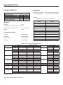
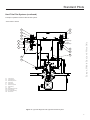
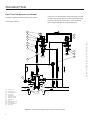
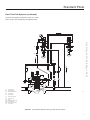
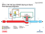
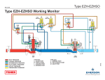
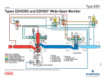
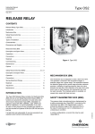
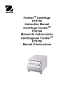
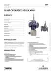
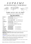
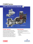
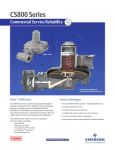
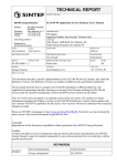
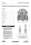
Standard Pilot Systems
Instruction Manual
NTAPIL0805
June 2010
Francel Pilot Systems
SUMMARY
Introduction ........................................................................ 1
Characteristics .................................................................... 2
Labelling ...................................................................................... 3
Description ......................................................................... 3
Principle of Operation ........................................................ 4
Startup ................................................................................ 10
Commissioning .................................................................. 10
Terms ................................................................................. 13
BSL 85 Pilot
Pre-expansion Determination ............................................. 13
Pilot Setting Ranges ........................................................... 15
Spare Parts......................................................................... 19
INTRODUCTION
Scope of Manual
This manual provides instructions for operation, startup,
commissioning and spare parts ordering for the different
Francel Pilot Systems.
Product Description
Two Francel Pilot Systems are available:
A90b
Compact Pilot
Figure 1. Francel Pilot Systems
• Compact Pilot (Distribution Applications)
The compact pilot is composed of a manometric preexpansion box, a manometric pre-expansion pilot box,
and a pilot body.
• BSL 85 Pilot
(Transmission Applications)
The BSL 85 pilot system is composed of a manometric
pre-expansion box, a manometric pre-expansion pilot
box and two pilot bodies. The BSL 85 permits all types of
failure modes.
• The BMP pilots with standard diaphragm are “FO”
• The BMP pilots with diaphragm bellows are “FC”
• The bellows are flattened in the case of overpressure but
with no leak to the outside.
Different connections permits the pilot to be used on a wide
range of EMERSON Pilot-Operated Regulators.
Two functional types of pressure reduction are available,
Hard Trim or Boot Trim Pilot System:
• Pressure Reduction with Actuator and Plug:
Pilot system loading by modulated pressure
• Pressure Reduction with Diaphragm-Plug:
Pilot system unloading by modulated pressure
By simply changing the BMP manometric box or spring the
setpoint range can be modified. No dismantling tool is required for this operation except in the case of BMP DR, DA,
MD or RJGI.
Europe, Middle East, and Africa Only
A90a
Options ............................................................................... 13
Standard Pilots
Regulators
CHARACTERISTICS
Transmission applications:
MPS, MP, EZH, BERTIN EZ, EZR
Distribution applications:
K1000, K3000, EZR, CRONOS
OPERATING PRESSURE
PSD
85 bar
Pumax
100 bar
Outlet pressure range
Pd
0.01 to 60 bar
OPERATING TEMPERATURE
TS
-20/60 °C
Maximum obtainable pressure
Terms
Table 1. Previous and Present Used Terms
Material
Pilot body:
PREVIOUS
PRESENT
Nozzle
Nozzle
Steel
Pilot Manometric Box BMP (spring case): Steel
Pilot Manometric Box BMP (cover):
Steel or Aluminium
Bracket:
Steel
Pilot block
Nozzle
Relay body
Pilot body
MZC
Spring case
RGMH
Cover
ADGJ
Pre-expansion relay (071,114, ...)
Connections Styles
RJGN
Pilot (071, 114, ...)
Pilot body:
1/4 NPT tapped
RJGF
BMP 114 MD
Manometer:
M10x100 tapped
ADGD
BMP 114 DR
BMP connection:
1/4 NPT tapped
ADGC
BMP 114 DA
BMP vent:
1/4 NPT tapped
RHGD
BMP 114 LD
Europe, Middle East, and Africa Only
Obtainable inlet pressure
Table 2. Setting Ranges for Manometric Boxes
SPRING
SIZE
SETTING RANGE Wds*
PILOT SYSTEM
Min
Max
2.0
113195
0.01
0.05
3.0
113197
0.05
0.18
4.0
113199
0.16
0.77
4.5
113200
0.25
1.20
5.5
113202
0.50
2.40
6.5
114139
1.00
4.80
4.5
113200
1.00
5.00
5.5
113202
2.00
10.50
X
X
6.5
114139
4.00
18.00
X
X
4.5
113200
2.00
10.50
X
X
5.5
113202
4.00
18.00
X
X
6.5
114139
8.00
35.00
X
X
227
6.5
114139
12.00
47.00
47
X
X
222
6.5
114139
30.00
60.00
70
X
X
5.5
113202
0.50
2.40
X
6.5
114139
1.20
4.80
X
4.0
116816
0.40
1.30
4.5
113200
0.25
1.20
5.5
113202
0.50
2.40
X
6.5
114139
1.20
4.80
X
Wire
162
114
71
236
114 DR
114 DA
114 MD
(mm)
DR: Differential can be set
DA: Differential can be adjusted
MD: Double Diaphragm
Other ranges available, please contact factory.
2
PSD
Reference
Pre-expansion
Pilot
X
5
X
X
10
X
X
X
X
X
X
20
35
100
X
*Wds: Set range applicable to a regulator for every BMP size
X
A91
Standard Pilots
LABELLING
See Table 2
Figure 2. Type BMP Label
Europe, Middle East, and Africa Only
DESCRIPTION
PD
RP
IP
PD
5
IP
4
3
1
6
2
A92
Figure 3. Body Labelling
Body Description (Figure 3)
13. Pre-expansion manometric box
1. Pilot feed
14. Pilot nozzle
2. Pilot impulse line (IP)
15. Pilot setting spring
3. Pre-expansion manometer
4. Pilot reject (RP)
16. Pilot manometric box
2 - Connecting parts (Figure 7)
5. Exterior manometer or relief valve (PD)
20. Pre-expansion relief valve
6. Mounting M8
21. Pre-expansion manometer
22. Fitted filter
Hard Trim Pilot System (Figures 4, 5 & 6)
and Boot Trim Pilot System (Figure 7)
23. Feed tap
1 - Pilot Assembly
25. Modulated pressure tap(1)
24. Slam-shut bypass tap
(if not incorporated)
10. Pilot body
26. Reject tap(1)
11. Pre-expansion nozzle
27. Restriction tap(2)
12. Pre-expansion setting spring
(1) Hard trim pilot system only
(2) Boot trim pilot system only
3
Standard Pilots
PRINCIPLE OF OPERATION
Hard Trim Pilot Systems
Principle of Operation based on Compact Pilot System
23
22
13
12
IS
21
11
Pilot feed
Pm
20
10
Pu
Pm
14
15
RP
Pu:
Pd:
Pm:
RP:
IP:
IS:
Inlet pressure
Outlet pressure
Modulated pressure
Pilot Reject
Pilot Impulse
Slam-Shut Impulse
Short IP
Pd
16
Long IP
A93
26
Figure 4. Principle of Operation with Compact Pilot System - Type K1000/K3000 and EZR Regulators
The regulator opens due to the increase (loading) of the
modulated pressure (Pm).
Opening
Closing
The flow demand decreases, the increase of the outlet pressure (Pd) is registered by the pilot-sensing element.
The flow demand increases, the decrease in outlet pressure
(Pd) is registered by the pilot-sensing element.
The increased outlet pressure overcomes the force of the
control spring, the pilot, then the pre-expansion relay, close.
Forced by the action of the control springs, the pilot, then the
pre-expansion relay, open.
The modulated pressure (Pm) bleeds through the reject
pilot (RP).
The pre-expansion pressure (Pup) feeds the pilot.
The modulated pressure (Pm) is fed to the pilot through the
actuator diaphragm.
The regulator OPENS.
4
The regulator CLOSES.
Europe, Middle East, and Africa Only
Atm
Standard Pilots
Hard Trim Pilot Systems (continued)
Principle of operation based on BSL 85 Pilot System
“Fail to Close” Version
20
10
10
14
11
21
Upper
Diaphragm
22
23
Europe, Middle East, and Africa Only
Lower
Diaphragm
F1
12
R1
15
PM
PR1
16
26
RP1
13
25
RM1
RP
Pu
IP
Pd
IS
Pu:
Pd:
Pm:
Inlet pressure
Outlet pressure
Modulated pressure
RP:
IP:
IS:
Pilot Reject
Pilot Impulse
Slam-Shut Impulse
R1:
F1:
RM1:
RP1:
PR1:
PM:
Pilot feed tap
Filter
Motorized Pressure tap
Pilot Reject tap
Pre-expansion Relay
Monitor Pilot
Figure 5. Type EZH Regulator with Type BSL 85 Pilot System
5
Standard Pilots
Hard Trim Pilot Systems (continued)
Principle of operation based on BSL 85 Pilot System
In this case, it is still possible to choose two types of regulators depending on their reaction in the case of failure mode.
“Fail to Open” Version
Figure 6a: the regulator spring tries to close, the “Fail to
Open” mode is managed by the appropriate pilot.
21
20
10
10
14
22
12
F2
23
15
R2
16
PA
PR2
13
RP2
25
RM2
RP
Pu
Pu:
Pd:
Pm:
Inlet pressure
Outlet pressure
Modulated pressure
RP:
IP:
IS:
ID:
Pilot Reject
Pilot Impulse
Slam-Shut Impulse
Differential Impulse
R2:
F2:
RM2:
RP2:
PR2:
PA:
Pilot Feed tap
Filter
Motorized Pressure tap
Pilot Reject tap
Pre-expansion Relay
Active Pilot
ID
IP
Pd
Figure 6a. Type EZHFO Regulator with Type BSL 85 Pilot System
6
26
Europe, Middle East, and Africa Only
11
Standard Pilots
Hard Trim Pilot Systems (continued)
Europe, Middle East, and Africa Only
Figure 6b: the regulator spring tries to open, the “Fail to
Open” mode is also managed by the regulator spring.
F2
R2
PA
PR2
RP2
IP
RM2
Pu
Pu:
Pd:
Pm:
Inlet pressure
Outlet pressure
Modulated pressure
RP:
IP:
IS:
Pilot Reject
Pilot Impulse
Slam-Shut Impulse
R2:
F2:
RM2:
RP2:
PR2:
PA:
Pilot Feed tap
Filter
Motorized Pressure tap
Pilot Reject tap
Pre-expansion Relay
Active Pilot
IP
RP
Pd
A94
Figure 6a. Type EZHSO Regulator with Type BSL 85 Pilot System
7
Standard Pilots
Boot Trim Pilot Systems
Principle of operation based on Compact Pilot System
22
27
10
12
11
13
21
Pup
14
Pm
16
RP
Pu
Pu :
Pd :
Pm :
RP :
IP :
IS :
Inlet pressure
Outlet pressure
Modulated pressure
Pilot Reject
Pilot Impulse
Slam-Shut Impulse
IP
15
Pd
IS
A94
Figure 7. Type EZR Regulator with Type Compact PIlot System
The regulator opens with a decrease (unloading) of the
modulated pressure (Pm).
Opening
Closing
The flow demand decreases, the increase in the outlet
pressure (Pd) is registered by the pilot-sensing element.
The flow demand increases, the decrease in the outlet
pressure (Pd) is registered by the pilot-sensing element.
The force applied on the pilot impulse is overcome by that
of the control spring, the pilot, then the pre-expansion relay
close.
Forced by the action of the control springs, the pilot, then the
pre-expansion relay, open.
The pilot flow decreases and becomes inferior to that of the
restriction tap (key 27).
The pilot flow increases and becomes superior to that of the
restriction tap (key 27).
The modulated pressure (Pm) increases.
The modulated pressure (Pm) bleeds to the oulet side
through the reject pilot (RP).
The regulator OPENS.
8
The regulator CLOSES.
Europe, Middle East, and Africa Only
20
Standard Pilots
Boot Trim Pilot Systems (continued)
Principle of operation based on BSL 85 Pilot System
22
13
12
27
10
21
11
20
10
Europe, Middle East, and Africa Only
14
15
16
Pm
RP
IP
Pd
Pu
IS
NC = F E R
B L AIT E = C LO ME
SE D
WH
NC = F E R
B L A T E = C L O ME
I
SE D
WH
Pu :
Pd :
Pm :
RP :
IP :
IS :
Inlet pressure
Outlet pressure
Modulated pressure
Pilot Reject
Pilot Impulse
Slam-Shut Impulse
Figure 8. Type EZR Regulator with Type BSL 85 PIlot System
9
Standard Pilots
Respect the instructions given in the instruction manual of
each regulator.
!
WARNING
• Only qualified personnel through training or
experience are authorised to install, service
or maintain equipment.
• Installation according to EN 12186 is recommended.
• No modification should be made to the
structure of the equipment (drilling, grinding, soldering...).
• The equipment should ne receive any type of
shock.
• The user should verify or carry out a protection adapted to the environment.
• Personal injury or equipment damage
due to bursting of pressure-containing
parts may occur. To avoid such injury or
damage, provide pressure relieving or
pressure-limiting devices to prevent service
conditions from exceeding those limits.
• Physical damage to the regulator can
break the pilot off the main valve, causing
personal injury and property damage due
to bursting of pressure-containing parts. To
avoid such injury and damage, install the
regulator in a safe location.
• Remove impulse (key 3)
– Check impulse element
– Control tightshut joints
Pilot Body (Figure 13)
• Remove nozzle(s) (pilot block(s)) (key 4)
– Screw M4
· Clean valve and seat
· Control tighshut joints
• Unscrew manometer (key 5)
– Flat spanner no. 14
• Remove flat ring (key 6)
• Unscrew relief valve (key 7)
– Flat spanner no. 19
Filter (Figure 10)
• Unscrew cap (key 8)
– 6-sided spanner no. 10
• Remove filter (key 9)
– Change the filter every year
Adjustment Tap (Figure 11)
• Unscrew stop point (key 10)
– Flat spanner no. 22
• Unscrew needle (key 11)
– Square spanner
· Control the seating of the seat and the needle
· Control the tighshut joint
NOTE
Install a cap, or fill the point (key 10) with
grease, for protection against aggression
from the exterior.
COMMISSIONING
Relief Valve (depending on version) (Figure 12)
Disassembly
• Unscrew screw (key 12)
– Flat screwdriver
Check the absence of pressure between inlet and outlet
valves.
Every year:
• Remove valve-plug (key 13)
– Check seat and valve-plug
Reassembly
• Disassemble the manometric boxes and nozzles.
Complet the above operations in reverse order.
• Control immediate spare parts.
Lightly grease all rings (silicone grease recommended).
• Change the fritted filter.
Lightly grease all threads (molycot grease).
Tools:
Flat spanners 8, 11, 13, 14, 19 ; Six-sided spanners 5, 10;
FRANCEL square spanner; Flat screwdriver and screw M4.
Manometric Box (BM) (Figure 9)
• Unscrew knob (key 1)
– Manually
• Unscrew screw (key 2)
– Spanner*
10
*Flat spanner
N° 11 for BMP 162 - N° 8 for BMP 114 and 071
6-sided spanner N° 5 for bellows BMP
Europe, Middle East, and Africa Only
STARTUP
Standard Pilots
1
2
5
6
A95
Figure 9. Manometric Box
7
4
BSL 85 Pre-expansion Body
Europe, Middle East, and Africa Only
3
9
8
A97
4
Figure 10. Filter
BSL 85 Pilot Body
10
11
A98
M4 screw
4
5
Figure 11. Setting Tap
6
A96
7
4
A96
13
12
Figure 12. Relief Valve
A99
Compact Pilot Body
Figure 13. Pilot System Body Types
11
Standard Pilots
Standard Connections
Table 3. Standard Connections
BERTIN EZ NO
MPNO
EZHFO, EZHSO
BERTIN EZ
MP
EZH
MPS
K3000
K1000
EZR
Stand-alone
X
X
X
X
Monitor
X
X
X
Working Monitor
X
X
Active
X
X
X
Stand-alone
X
X
X
X
REGULATORS
Assembly Type
Monitor
X
X
Working Monitor
X
X
Active
X
ADGE Version
Stand-alone
X
X
X
X
Working Monitor
Contact factory
Active
A101
Principle
Variable Pressure Metering (CPV)
A port plate causes loss in the load, which causes flow
increase. The pressure between the regulator and the port
plate increases with the flow. The meter allows the flow to
increase (in m3/h(N)) as the pressure increases when the
flow is high.
Elements:
• Pilot System: - One pre-expansion relay with
adjustable differential
(BMP 114 DR)
- One standard pilot
Goal: Increase meter dynamics
• Meter
Determination of Characteristics
• Port Plate
Pre-expansion
Differential
Contact factory.
Pup
Standard
Pilot
Pm
Reject to Pi
Pu
Pd
Pi
METER
Q
PORT PLATE
REGULATOR
A119
Figure 14. Port Plate
12
Europe, Middle East, and Africa Only
Monitor
Variable Pressure
Meter Version
Standard Pilots
PRE-EXPANSION DETERMINATION
OPTIONS
Table 4. Pre-expansion per Regulator (bar)
(Superior to downstream pressure (Pd))
RPE (Electric Heater)
The RPE is used for reheating gas supplying pressure
reducing regulator pilots. It avoids the inconveniences
caused by freezing which occur during large pressure drops.
(See instruction manual NTARPE).
ADGE 1” (Pre-expansion Exchanger)
MIN
NOMINAL
MAX
EZR
0.50
0.80
1.50
K1000
0.25
0.50
1.00
MPS
3.00
6.00
8.00
A104
Mass volume corrector
Flow limiter
Remote control setting
Table 5. Adjustable Pre-expansion Differential for EZH,
EZH FO, EZHSO, MP, Bertin EZ,
Working Monitor Regulator
or CPV Metering
Contact factory
TERMS
MIN
NOMINAL
MAX
MP
Pd + 1.2
Pd + 2.4
Pd + 4.8
BERTIN EZ
Pd + 1.2
Pd + 2.4
Pd + 4.8
Pd + 2
Pd + 4
Pd + 4.8
Pd + 1.7
Pd + 2
Pd + 3
MPS
Failure Modes
EZH, EZH FO,
EZHSO
FO: Fail to Open
A105
Regulator Opens in the case of failure mode
The regulator tends to automatically open in the case
of failure of the main diaphragm or when there is an
interruption of the energy required for the displacement of
the regulation unit.
FC: Fail to Close
Regulator Closes in the case of failure mode
The regulator tends to automatically close in the case
of failure of the main diaphragm or when there is an
interruption of the energy required for the displacement of
the regulation unit.
Table 6. Adjustable Pre-expansion Differential for
Type FO Regulators
MPNO
BERTIN EZ NO
ACTUATOR
NOMINAL
269
Pd + 0.8
374
Pd + 1.1
Adjustable from 0.4 to 1.3 bar
Adjustable according to size of actuator (factory set)
A106
Equipment:
- FO design: EZHFO - EZHSO - BERTIN EZ NO
MPNO
- FC design: EZH - BERTIN EZ - MPNF
Type BMP 114 MD Double-Diaphragm Pilot
(Figure 5)
The manometric box is equipped with two integral
diaphragms. The volume between these two diaphragms is
related to the driving pressure of the actuator.
Failure of the upper diaphragm will cause balance between
the driving pressure and the outlet pressure. Failure of the
lower diaphragm will cause evacuation the driving pressure
to the atmosphere.
In both cases the equipment tends to close due to lack of
driving pressure (Fail to Close).
13
Europe, Middle East, and Africa Only
The ADGE 1” replaces the standard pre-expansion relay. It
permits the gas to be reheated beyond pre-expansion without
using external energy sources. (See instruction manual
NTAADGE1). See table 3 for standard configurations.
Standard Pilots
Operating Instructions and Regulation
Optimization
Hard trim
pilot systems
(Figures 3, 4, 5)
Boot trim
pilot systems
(Figure 6)
UNIT OR PARAMETER
INDICATIONS
INSTABILITY
SLOW REACTION
LACK OF
PRECISION
Modulated pressure
valve (key 25)
Wide open.
All settings available except
completely closed
Progressively close,
without completely closing
Open as wide as
possible
No incidence
Reject tap
(key.26)
Open 3/4 turn.
All settings available
Open by successive fractions
Close by successive fractions
Pre-expansion relay
(key 13)
See table 4
Decrease the pre-expansion by
successive fractions
Increase the pre-expansion by
successive fractions
Pilot vent valve
(BMP 162)
Open 1/2 turn.
All settings available except
completely closed
Look for the best position
between 1/4 and 2 turns
Feeding tap
(key 29)
Open 1/2 turn.
All settings available
Open by successive fractions
Close by successive fractions
Pre-expansion relay
(key 13)
See table 5
Decrease the pre-expansion by
successive fractions
Increase by pre-expansion by
successive fractions
Progressively open
No incidence
A107
14
Europe, Middle East, and Africa Only
Table 7. Operating Instructions and Regulation Optimization
0.05 to 0.18
0.18 to 0.77
0.77 to 1.20
0.10
0.30
1.00
1.20 to 2.40
1.00
2.00
10.50 to 16.00
0.77 to 1.20
0.30
16.00
0.18 to 0.77
0.10
2.40. to 4.80
0.05 to 0.18
0.02
4.80 to 10.50
0.01 to 0.05
16.00
8.00
10.50 to 18.00
8.00
4.00
2.40. to 4.80
4.80 to 10.50
4.00
1.00 to 2.40
0.01 to 0.05
0.02
2.00
Range
Nominal
Pd
Pd (bar)
Bellows
Diaphragm
Bellows
Diaphragm
Type
236
071
114
236
071
114
Size
35
20
10
35
20
10
PSD
(bar)
PRE-EXPANSION RELAY
6.5
5.5
4.5
5.5
4.5
6.5
5.5
4.5
5.5
Wire
(mm)
Diaphragm
Type
071
114
162
071
114
162
Size
20
10
5
20
10
5
PSD
(bar)
PILOTAGE
6.5
5.5
6.5
5.5
4.5
4
3
2
6.5
5.5
6.5
5.5
4.5
4
3
2
Wire
(mm)
Europe, Middle East, and Africa Only
(1) Note: If Pu <= 10 bar and Pd <= 8 bar. the relief valve is removed and replaced by a plug.
K1000
K3000
EZR
DISTRIBUTION
REGULATORS
0 - 40
0 - 16
0-6
0 - 40
0 - 16
0-6
MANOMETER
RANGE
(bar)
24.3
10.3
24.3
10.3
Maxi
Setting
(bar)
18
13
7
5
23
16
10
7
6
5
Setting
(bar)
RELIEF VALVE (1)
Standard Pilots
PILOT SETTING RANGES
Table 8. Distribution Regulators Range
A108
15
16
EZHFO. EZHSO
MPNO
BERTIN EZ NO
MPS
EZH
MP
BERTIN EZ
TRANSMISSION
REGULATORS
18.00 to 35.00
35.00 to 47.00
47.00 to 60.00
32.00
40.00
50.00
2.40 to 4.80
4.80 to 10.50
4.00
8.00
10.50 to 18.00
1.00 to 2.40
2.00
16.00
47.00 to 60.00
50.00
4.80 to 10.50
8.00
35.00 to 47.00
2.40 to 4.80
4.00
18.00 to 35.00
1.00 to 2.40
2.00
40.00
47.00 to 60.00
50.00
32.00
35.00 to 47.00
40.00
10.50 to 18.00
18.00 to 35.00
32.00
16.00
10.50 to 18.00
4.80 to 10.50
8.00
16.00
1.00 to 2.40
2.40 to 4.80
4.00
47.00 to 60.00
50.00
2.00
35.00 to 47.00
4.80 to 10.50
8.00
18.00 to 35.00
2.40 to 4.80
4.00
40.00
1.00 to 2.40
2.00
32.00
47.00 to 60.00
50.00
10.50 to 18.00
35.00 to 47.00
40.00
16.00
18.00 to 35.00
4.80 to 10.50
8.00
10.50 to 18.00
2.40 to 4.80
4.00
32.00
1.00 to 2.40
2.00
16.00
Range
Nominal
Pd
Pd (bar)
Diaphragm
Bellows
Diaphragm
Type
A109
100
70
47
35
100
PSD
(bar)
3.2
6.5
EZHSO
5.5
EZHFO
4
6.5
5.5
5.5
6.5
Wire
(mm)
Soufflet
Membrane
Soufflet
Membrane
Bellows
Diaphragm
Bellows
Diaphragm
Bellows
Diaphragm
Type
222
227
236
071
114
222
227
236
071
114
222
227
236
071
114
222
227
236
114 MD
222
227
236
114 MD
Size
Nozzle
70
47
35
20
10
70
47
35
20
10
70
47
35
20
10
70
47
35
100
70
47
35
100
PSD
(bar)
4.0
PILOT SYSTEM
6.5
5.5
6.5
5.5
6.5
5.5
6.5
5.5
6.5
5.5
6.5
5.5
6.5
5.5
4.5
6.5
5.5
6.5
5.5
4.5
6.5
5.5
Wire
(mm)
Europe, Middle East, and Africa Only
114 DR
114 DA
222
227
236
114 DR
Size
Nozzle
PRE-EXPANSION RELAY
0 - 100
0 - 40
0 - 16
0 - 100
0 - 40
0 - 16
0 - 100
0 - 40
0 - 16
0 - 100
0 - 40
0 - 16
0 - 100
0 - 40
0 - 16
MANOMETER
RANGE
(bar)
70
40.3
24.3
10.3
70
40.3
24.3
10.3
70
24.3
70
40.3
24.3
10.3
70
40.3
24.3
10.3
Max.
Setting
(bar)
65
52
40
23
16
10
8
65
52
40
23
16
10
8
69
56
44
27
20
14
12
65
52
40
23
16
10
8
65
52
40
23
16
10
8
Setting
(bar)
RELIEF VALVE
Standard Pilots
PILOT SETTING RANGES (continued)
Table 9. Transmission Regulator Range
Standard Pilots
PILOT SETTING RANGES (continued)
Table 10. Transmission Regulators – Working Monitor
PRE-EXPANSION RELAY
PILOT SYSTEM
Pd (bar)
MP
BERTIN EZ
EZH
MPNO
EZHFO. EZHSO
Nozzle
Nominal
Pd
Range
2.00
1.00 to 2.40
Type
3.2
Tightshut Nozzle
PSD
(bar)
Size
Fil
(mm)
Type
Taille
Diaphragm 114 MD
4.00
2.40 to 4.80
8.00
4.80 to 10.50
16.00
10.50 to 18.00
32.00
18.00 to 35.00
40.00
50.00
2.00
1.00 to 2.40
4.00
2.40 to 4.80
8.00
4.80 to 10.50
16.00
10.50 to 18.00
32.00
18.00 to 35.00
40.00
35.00 to 47.00
50.00
47.00 to 60.00
2.00
1.00 to 2.40
4.00
2.40 to 4.80
8.00
4.80 to 10.50
16.00
10.50 to 18.00
32.00
18.00 to 35.00
40.00
35.00 to 47.00
50.00
47.00 to 60.00
2.00
1.00 to 2.400
4.00
2.40 to 4.80
8.00
4.80 to 10.50
16.00
10.50 to 18.00
32.00
18.00 to 35.00
40.00
35.00 to 47.00
50.00
47.00 to 60.00
4.0
PSD
(bar)
Fil
(mm)
MANOMETER
RANGE
(bar)
RELIEF VALVE
Max.
Setting
(bar)
Setting
(bar)
5.5
100
6.5
4.5
6.5
236
35
5.5
35.00 to 47.00
227
47
6.5
47.00 to 60.00
222
70
Bellows
114 DR
Diaphragm 114MD
100
5.5
6.5
5.5
236
35
227
47
222
70
4.5
Bellows
100
Diaphragm
5.5
114
6.5
5.5
10
6.5
Diaphragm
114 DA
071
4
Bellows
5.5
Diaphragm
EZHFO
114 DR
6.5
EZHSO
Bellows
5.5
20
236
35
227
47
222
70
114
10
071
20
236
35
227
47
222
70
The manometer and relief valve
are defined according to the Pi
(see table below)
6.5
5.5
6.5
5.5
6.5
Table 11. Pi Range for Definition of Manometer and Relief Valve Values
PILOT SYSTEM
Pi (bar)
TRANSMISSION
REGULATORS
MP
MPNO
EZH
BERTIN EZ
EZHFO
EZHSO
Tightshut Nozzle
Nominal Pi
Range
2.00
1.00 to 2.40
4.00
2.40 to 4.80
8.00
4.80 to 10.50
16.00
10.50 to 18.00
32.00
18.00 to 35.00
40.00
35.00 to 47.00
50.00
47.00 to 60.00
Type
Size
PSD
(bar)
114
10
Wire
(mm)
5.5
MANOMETER
RANGE
(bar)
0 - 16
RELIEF VALVE
Max Setting
(bar)
10.3
6.5
Diaphragm
Bellows
4.0
071
20
236
35
227
47
222
70
5.5
6.5
Setting
(bar)
8
10
0 - 40
24.3
40.3
0 - 100
70
16
23
40
52
65
A110
17
Europe, Middle East, and Africa Only
TRANSMISSION
REGULATORS
18
MPNO
BERTIN EZ NO
EZHFO. EZHSO
MPS
EZH
MP
BERTIN EZ
TRANSMISSION
REGULATORS
50.00
47.00 to 60.00
35.00 to 47.00
40.00
4.80 to 10.50
8.00
18.00 to 35.00
2.40 to 4.80
4.00
10.50 to 18.00
1.00 to 2.40
2.00
16.00
47.00 to 60.00
50.00
32.00
35.00 to 47.00
4.80 to 10.50
8.00
40.00
2.40 to 4.80
4.00
18.00 to 35.00
1.00 to 2.40
2.00
10.50 to 18.00
47.00 to 60.00
50.00
32.00
35.00 to 47.00
16.00
18.00 to 35.00
40.00
4.80 to 10.50
8.00
32.00
2.40 to 4.80
4.00
10.50 to 18.00
1.00 to 2.40
2.00
16.00
47.00 to 60.00
50.00
4.80 to 10.50
8.00
35.00 to 47.00
2.40 to 4.80
4.00
40.00
1.00 to 2.40
2.00
18.00 to 35.00
47.00 to 60.00
50.00
32.00
35.00 to 47.00
40.00
10.50 to 18.00
18.00 to 35.00
32.00
16.00
4.80 to 10.50
10.50 to 18.00
2.40 to 4.80
4.00
8.00
1.00 to 2.40
2.00
16.00
Range
Nominal
Pd
Pd (bar)
Diaphragm
Type
A119
100
PSD
(bar)
3.2
4
6.5
EZHSO
5.5
EZHFO
6.5
5.5
6.5
Wire
(mm)
Bellows
Diaphragm
Bellows
Diaphragm
Bellows
Diaphragm
Bellows
Diaphragm
Bellows
Diaphragm
Type
222
227
236
071
114
222
227
236
071
114
222
227
236
071
114
222
227
236
114 MD
222
227
236
114 MD
Size
Nozzle
70
47
35
20
10
70
47
35
20
10
70
47
35
20
10
70
47
35
100
70
47
35
100
PSD
(bar)
4.0
PILOT SYSTEM
6.5
5.5
6.5
5.5
6.5
5.5
6.5
5.5
6.5
5.5
6.5
5.5
6.5
5.5
4.5
6.5
5.5
6.5
5.5
4.5
6.5
5.5
Wire
(mm)
Europe, Middle East, and Africa Only
114 DA
114 DR
Size
Nozzle
PRE-EXPANSION RELAY
Tarage
Maxi (bar)
Réglage
(bar)
RELIEF VALVE
The manometer and relief valve are
defined according to configuration
(see page 18)
MANOMETER
RANGE
(bar)
Standard Pilots
PILOT SETTING RANGES (continued)
Table 11. Transmission CPV Regulators
Standard Pilots
SPARE PARTS
Table 13. Spare Parts (Figures 15 to 19)
DIAPHRAGM BMP SIZE
BELLOWS BMP SIZE
DESCRIPTION
71
Pre-expansion BMP
198742
Pilot BMP
195574
162
195606
114
114 DA
114 DR
198743
199191
199190
195373
114 MD
199187
1*
O-ring
2
BMP Spring case
114890
144259
115625
145658
3*
Impulse element
142549
137906
117562
144910
4
Nut
5
Spring box
6
Spring carrier
250
236
227
222
198753
198750
198751
198752
196584
196580
196576
196574
400520
121560
180923
180922
180924
404006
124524
122798
122841
145659
129833
102351
7
Adjustment knob
8*
Pre-expansion BMP
O-ring
400512
9
Contact stem
145116
118018
145117
10
Nut
404002
404003
404002
11
Screw
402008
402019
402010
12
Plate
108552
102113
13
Setting spring
14
Spring
115029
15*
O-ring
400068
16
Spring carrier
140769
17
Washer
18
Screw
19
Screw
402019
20*
O-ring
400220
21
Spacer
144945
22
Crown
145661
23
MD bottom
145662
24
O-ring
400522
25
O-ring
400506
26
DR-DA bottom
145663
Vent
Restriction vent
180971
Europe, Middle East, and Africa Only
KEY
105184
145660
181362
181363
400512
105184
400512
145119
144943
145118
402043
402515
404003
402040
105235
See table 2
405007
405253
402506
27A5516X012
27A5516X012
27A5516X012
180874
* 1st necessity parts
19
Standard Pilots
SPARE PARTS (continued)
Manometric Boxes
8
9
1
10
2
14
1
8
2
9
3
3
4
12
5
13
6
11
17
13
18
5
7
6
7
A113a
A113b
Figure 16. BMP 236, 222, 227
Figure 15. BMP 071, 114, 162
9
8
2
1
20
11
17
3
10
12
9
8
5
4
2
1
13
6
11
25
20
17
3
10
12
5
4
13
6
26
9
1
24
2
11
19
12
3
A113e
7
Figure 17. BMP 114 DA
20
22
3
10
21
17
25
20
26
24
13
19
5
7
19
4
6
23
7
A113c
Figure 18. BMP 114 DR
20
A113d
Figure 19. BMP 114 MD
Europe, Middle East, and Africa Only
16
15
11
Standard Pilots
SPARE PARTS (continued)
Table 14. Spare Parts for Nozzles
NOZZLE TYPE
PRE-EXPANSION RELAY
PILOT
Circular
mark
Circular
mark
3.2
(1 O-ring)
Transmission
Applications
25 to 80 bar
181083
Europe, Middle East, and Africa Only
181250
Circular
mark
3.2 ADGE
(2 O-rings)
181292
3.2 ADGT
(1 O-ring)
181097
4
(1 pre-expansion
O-ring)
Distribution
Applications
0 to 70 bar
(2 O-rings for pilot)
181249
180373
181248
180372
4E
(3 O-rings)
Circular
mark
181251
Circular
mark
180826
21
Standard Pilots
SPARE PARTS (continued)
27
28
29
Europe, Middle East, and Africa Only
30
A115b
24
25
26
Figure 20. Adjustment Tap
31
32
35
33
34
A116b
Figure 21. Pilot Body
Table 15. Adjustment Tap Spare Parts
DESCRIPTION
Table 16. Pilot Body Spare Parts
KEY.
CODE
Body
24
144491
O-ring
25
400506
Masking
26
Square spanner
60° cone gauge
DESCRIPTION
KEY.
CODE
Pilot body
31
144833
1/4” NPT cap
32
135232
119946
Pilot body cap
33
143606
27
461508
Cap O-ring
34
400520
28
121823
M10x150 cap
35
408308
7° cone gauge with permanent leak
29
132161
7° cone gauge
30
144857
A116a
22
Standard Pilots
SPARE PARTS (continued)
36
41
37
45
44
44
45
43
39
42
38
A117b
Europe, Middle East, and Africa Only
40
Figure 22. Filter
Relief Valve Setting (factory set)
Table 17. Filter Spare Parts
DESCRIPTION
Normal or Monitor Assembly:
KEY.
CODE
SPS filter body
36
144108
Filter O-ring
37
401308
MPNO Assembly:
Cap O-ring
38
400517
Spring Pd max + Pup maxi differential (1.3 bar) + 1 bar
Filter cap
39
118188
EZHFO, EZHSO Assembly:
Reducer
40
408208
Filter holder
41
144885
Working Monitor Assembly:
Cap
42
408309
Spring Pi max + Pup maxi differential + 1 bar
CPV Assembly:
Spring Pd max + Pup max + 1 bar
Spring Pd max + Pup maxi differential (2 bar) + 1 bar
F tee
43
408556
Spring
44
118189
Filter
45
118926
Pi max induced by the meter + Pup maxi differential + 1 bar
A117a
Table 18. Relief Valve Codes
Manometric Ranges
Normal or Monitor Assembly:
(Spring Pd max + Pup max + 1 bar)/0.75
SETTING RANGE (bar)
CODE
3.5 - 10.3
460063
MPNO Assembly:
10 - 24.3
460064
24 - 40.3
460065
(Spring Pd max + Pup maxi differential (1.3 bar) +
1 bar)/0.75
20 - 70
181257
EZHFO, EZHSO Assembly:
A118
Tableau 19. Manometer Codes
(Spring Pd max + Pup maxi differential
(2 bar) + 1 bar)/0.75
Working Monitor Assembly:
CODE
READING RANGE
(bar)
Back Plug
Lower Plug
0-4
460376
460425
0-6
460381
(Spring Pi max + Pup maxi differential + 1 bar)/0.75
0 - 16
460377
460350
0 - 40
460378
460351
0 - 100
460379
CPV Metering:
(Pi max induced by the meter + Pup maxi differential +
1 bar)/0.75
A119
23
Standard Pilots
Note
The max Pi induced by the meter may require
a manometer set at a high range, this may
restrict the setting of the pre-expansion
differential. However it is possible to install a
precise manometer when setting by using an
adapter on an available tapping of the pilot’s
body.
To check the different values required for settings see below:
• Spring Pd max:
see table 2
• Pup max:
see table 4
• Pup maxi differential: see table 5
see table 2
• Pi max induced by the meter, contact factory
Natural Gas Technologies
Regulator Division
Emerson Process Management
Z.A. La Croix Saint Mathieu
28320 Gallardon, France
Tel : +33 (0)2 37 33 47 00
Fax : +33 (0)2 37 31 46 56
Pour plus d’information visiter : www.emersonprocess.com/regulators
Le logo Emerson est une marque commerciale et une marque de service de Emerson Electric Co. Toutes les autres marques appartiennent à leurs propriétaires respectifs. Francel est une marque
appartenant à Francel S.A., une succursale d’Emerson Process Management.
Les renseignements contenus dans cette publication sont présentés uniquement à titre informatif et, bien que tout ait été fait pour assurer leur exactitude, ils ne doivent pas être interprétés comme
des garanties, expresses ou tacites, en ce qui concerne les produits ou services décrits ici ou leur usage ou applicabilité. Nous nous réservons le droit de modifier ou d’améliorer la conception ou les
spécifications de ces produits à n’importe quel moment, sans préavis.
Francel décline toute responsabilité en ce qui concerne la sélection, l’utilisation ou la maintenance d’un produit. La responsabilité de la sélection, de l’utilisation et de la maintenance de tout produit
Francel incombe uniquement à l’utilisateur.
©Francel S.A., 2007; Tous droits réservés
Europe, Middle East, and Africa Only
• Spring Pi max: