1
Surge Protection
TM
For Business-Critical Continuity
Communications/Data/Signal Line Surge Protection
Product Catalog
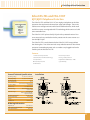
Mission-Critical Voice and Data
Signal Protection
Unmatched Protection for
Peace of Mind … Think of the investment your
company has made in sophisticated communications
systems. Now think how costly it would be to your
company if this mission-critical equipment went down.
The fact is — in a nanosecond — power surges, spikes
and transients can compromise or totally disrupt voice
and data communications, costing thousands in repairs
and lost productivity.
The stakes are far too high to place your trust in
anything but the best — Emerson Network Power Surge
Protection products.
Our Transient Voltage Surge Suppression (TVSS)
and data/signal line protection products provide
the protection you need to help eliminate damage,
disruption and costly downtime. Plus, all of the
power quality solutions in this catalog are backed by
a team of power quality specialists who understand
communications systems as thoroughly as the products
they sell.
Let Emerson Network Power Surge Protection provide
unmatched protection and peace of mind.
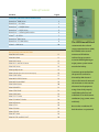
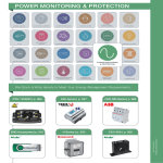
Table of Contents
Products
Page #
TRANSIENT VOLTAGE SURGE SUPPRESSION
PowerSure™ DMK Series
2
PowerSure™ — IH Series
3
PowerSure™ — LPM/IM Series
4
PowerSure — LPL/IL Series
5
PowerSure™ — Ordering Information
6
Islatrol — SP-6TVN
7
PowerSure EMC Series
8
PowerSure™ TCS-HW Series
9
™
™
™
Islatrol — RM Series
™
10
The IEEE Emerald Book
recommends that a listed
surge protection device (SPD)
be installed at the service
DATA/SIGNAL LINE PROTECTION
Edco RM-CAT6 Series
11
entrance of all facilities
Edco RM-CXO6
11
to divert large transients
Edco PLP-S Series
12
associated with lightning or
Edco FAS-1 and FAS-2 Series
13
major power system events
Edco PHC Series
14
outside the facility.
Edco RJA-RJD Series
15
Edco H Series (and TTA-2 Test Point Adaptor)
16
Edco COHP Series
17
Edco MEGA-TEK 25 Series
18
Edco MGB Ground Rail
19
Edco PC642 Series
20
Edco PC642PTU
21
Edco CAT6-5 POE
21
Edco LCDP Series
22
Edco TCS-T1 Series
23
Edco TCS-Multi T1 Series
24
Edco DCB Series
25
Edco CCTV-1
26
Edco CX Series
26
Edco CATV-DF
27
Edco NET Series
28
Edco FAS-TEL and FAS-31XT
29
Transients generated within
the premises can best be
diverted by SPDs located
close to the internal source of
the transients or close to the
electronic load equipment,
using a listed and properly
rated SPD applied to each
individual or set of electronic
conductors (e.g. power, voice
and data).
Best results are obtained if
both locations are protected.
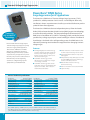
Transient Voltage Surge Suppression
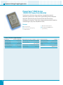
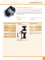
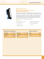
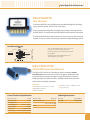
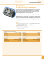
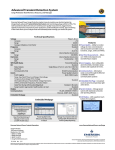
PowerSure® DMK Series
Surge Suppression for AC Applications
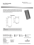
The PowerSure® DMK Series of Transient Voltage Surge Suppressors (TVSS)
provides fast, reliable protection for AC circuits. A small footprint allows easy
installation in almost any environment. Install at your critical distribution panel to
protect all down-line equipment.
The PowerSure® DMK Series features independent primary Silicon Avalanche
Diode (SAD) and secondary Metal Oxide Varistor (MOV) suppression technology
to ensure continued protection. The latest technological advancement of the
DMK Series is the addition of V3 SHIELD™ Technology, which provides the lowestpossible clamp voltage to peak pulse current handling far in excess of traditional
fused designs. Combined with a solid grounding system, the DMK Series is the
ultimate in protecting sensitive electronic equipment from damaging transient
voltage surges.
Featuring
NTI V3 SHIELD ™
Technology
Emerson Network Power designs superior
Transient Voltage Surge Suppression (TVSS)
devices for a variety of field applications.
Features
The PowerSure® DMK Series is available
■Status indication on each module to show
normal compromised suppression status
■N ondegrading Bipolar SAD technology
provides reliable performance with the
lowest-possible clamping voltage and
fastest response time in comparison to
other TVSS technologies
with various configurations and energyhandling ratings to ensure the proper level
of protection for your application. As part of
the total power protection solution, Emerson
■F ield replaceable modules for easy repair
and upgrade
■I ndependent primary SAD suppression and
secondary MOV suppression technology
ensures continued protection
■V 3 SHIELD ™ Technology provides
thermal protection against prolonged
over-voltage conditions
Network Power provides engineering
assistance to configure the appropriate
equipment for your individual needs.
■Remote failure indication for long
distance monitoring
■V 3 SHIELD ™ Technology allows actual
peak pulse current to be handled by the
suppression module, well in excess to
traditional fused modules
■I nterior and exterior enclosures available
■3 year warranty
General Technical Specifications
Part Number
PowerSure® DMK-B
Part Number
PowerSure® DMK-C
Operating Voltage
120/240 VAC Split Phase
Operating Voltage
Clamping Voltage 211 VAC
Clamping Voltage 211 VAC
Operating Current
NA, Parallel
Operating Current
NA, Parallel
Total Peak Surge Current
Operating Frequency
156kA
50/60 Hz
120/208 VAC 3 Phase Wye
Total Peak Surge Current
Operating Frequency
156kA
50/60 Hz
EMI Attenuation NA
EMI Attenuation NA
SPD Technology
SAD / MOV
SPD Technology
SAD / MOV
Modes of Protection
L-L & L-N (Standard), N-G .
(Enhanced Mode option)
Modes of Protection
L-L & L-N (Standard), N-G .
(Enhanced Mode option)
Status Indication
Power On & MOVs functional
Status Indication
Power On & MOVs functional
Connection Type
Wire Leads
Connection Type
Wire Leads
Operating Temperature
Dimensions (Inches)
Weight
Certifications
-40°C to +50°C
14H x 12W x 6D
22 lbs
UL 1449
Operating Temperature
Dimensions (Inches)
Weight
Certifications
-40°C to +50°C
20H x 12W x 6D
30 lbs
UL 1449
Notes: NEMA 1 (interior) or NEMA 4 (exterior) enclosures available. All units are UL 1449 Listed. Enhanced
mode (N-G) protection option available. All units come standard with Remote Failure Indication. Counter
option is available with a transient counter (interior enclosure only).
2
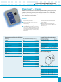
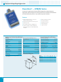
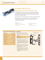
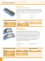
Transient Voltage Surge Suppression
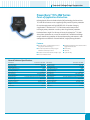
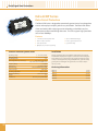
PowerSure® — IH Series
Modular Surge Protective Device (SPD) capable of handling the high-impulse,
potentially damaging transients commonly found at the service entrance or
distribution panels. Its robust design allows for placement and protection in the
most severe exposure locations.
Features
■Status indication includes: audible alarm,
form C contact, and internal/external
status indication
■S urge current capacity — 100,000 to
400,000 Amps per phase
■Replaceable modules ensure protected
mode flexibility
■A ll voltage and phase configurations
■U nique MOV/silver link fuse array enables
the IH Series to deliver the industry’s most
robust design; Coordination between fuse
gauge and MOV ensures repeatable strike
performance
Performance Technical Specifications
■O ptional equipment includes rotary
disconnect, surge counter, NEMA 3R, 4 or
4X enclosures
■5 year warranty
General Technical Specifications
Clamping
Peak Surge Current Capability (8 x 20 µs)
Operating Voltage Range
+/- 15%
UL 1449 Classification*
Model: IHxxxx400
Fault Current Rating (AIC)
200 kAIC
Phase:
400,000 Amps
Operating Frequency Range
Line to Neutral
400 Volts
L-N:
200,000 Amps
Capacity
Line to Line
800 Volts
L-L:
200,000 Amps
50 V EMI/RFI Attenuation
Line to Ground
400 Volts
L-G:
200,000 Amps
Response Time
Neutral to Ground
400 Volts
N-G:
200,000 Amps
Operating Temperature
120/208
277/480
Line to Neutral
Line to Line
Phase: 200,000 Amps
Certifications
Warranty
1,500 Volts
L-N:
100,000 Amps
Line to Ground
800 Volts
L-L:
100,000 Amps
Neutral to Ground
800 Volts
L-G: 100,000 Amps
N-G:
100,000 Amps
480
Line to Line
1,500 Volts
Model: IHxxxx200-2
Line to Ground
1,500 Volts
Phase: 200,000 Amps
L-N: 200,000 Amps
L-L: 200,000 Amps
* UL classifications for other voltages available
upon request.
50 dB
< 0.5 ns
-40°C to +50°C
Operating Humidity
Model: IHxxxx200
800 Volts
47–63 Hz
Continuous
L-G: N/A
N-G:
200,000 Amps
0% to 95%
UL 1449, 1283, CUL, CE
5 Year
Dimensional Diagram
Model: IHxxxx100-2
Phase: 100,000 Amps
L-N: 100,000 Amps
L-L:
100,000 Amps
L-G: N/A
N-G:
100,000 Amp
ModelA
BC
IHxxxY400
14
16
DE
8 16.75 12
F
.31
IHxxxD400
16
14
8 16.75 12
.31
IHxxxY200-2
16
14
8 16.75 12
.31
IHxxxD200-2
16
14
8 16.75 12
.31
IHxxxY200
16
14
8 16.75 12
.31
IHxxxD200
16
14
8 16.75 12
.31
IHxxxY100-2
16
14
8 16.75 12
.31
IHxxxD100-2
16
14
8 16.75 12
.31
3
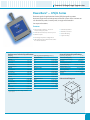
Transient Voltage Surge Suppression
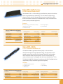
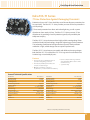
PowerSure® — LPM/IM Series
A compact Surge Protective Device (SPD) designed to protect electronic
equipment and microprocessor-based systems from transients on distribution
and sub-distribution panels, or any medium exposure locations.
Features
Surge current capacity — 100,000 to
160,000 Amps per phase
Nema 12 metal enclosure
All mode and 2 mode protection option
Thermal protection
Small footprints
Silver link fusing
All voltage and phase configurations
5 year warranty
Sand encapsulation
Form C contact for remote indication,
LED status indication, and audible alarm
standard
Performance Technical Specifications
Peak Surge Current Capability (8 x 20 µs)
Operating Voltage Range
+/- 15%
UL 1449 Classification*
Model: IMxxxx160
Fault Current Rating (AIC)
65 kAIC
Phase:
120/208
160,000 Amps
Operating Frequency Range
Line to Neutral
400 Volts
L-N:
80,000 Amps
Capacity
Line to Line
800 Volts
L-L:
80,000 Amps
50 V EMI/RFI Attenuation
Line to Ground
400 Volts
L-G:
80,000 Amps
Dry Contact Rating
Neutral to Ground
400 Volts
N-G:
80,000 Amps
Response Time
277/480
Line to Neutral
Model: IMxxxx100-2
800 Volts
< 0.5 ns
Operating Temperature
100,000 Amps
Operating Humidity
L-N:
100,000 Amps
Certifications
Line to Ground
800 Volts
L-L:
100,000 Amps
Warranty
Neutral to Ground
800 Volts
L-G:
N/A
N-G:
Line to Line
1,500 Volts
Line to Ground
1,500 Volts
* UL classifications for other voltages available
upon request.
40 dB
125 VAC, 8A, 1.0 pf
Phase:
480
47–63 Hz
Continuous
1,500 Volts
Line to Line
4
General Technical Specifications
Clamping
-45°C to +50°C
0% to 95%
UL 1449, CUL
5 Year
100,000 Amps
Dimensional Diagram
Model
A
B
C
D
E
F
IMxxxY160
8
6
4
8.75
4
.31
IMxxxD160
8
6
4
8.75
4
.31
IMxxxY100-2
6
4
3
6.75
2
.31
IMxxxD100-2
6
4
3
6.75
2
.31
Transient Voltage Surge Suppression
PowerSure® — LPL/IL Series
Electronic grade Surge Protective Device (SPD) designed to protect
electronic equipment and microprocessor-based systems from transients on
sub-distribution panels, branch panels, or equipment located in
low exposure locations.
Features
Surge current capacity — 25,000 to
100,000 Amps per phase
Sand encapsulation
All mode and 2 mode protection option
Silver link fusing
Small footprint
5 year warranty
Thermal protection
All voltage and phase configurations
LED status indication and form C contact
for remote indication
Performance Technical Specifications
General Technical Specifications
Clamping
Peak Surge Current Capability (8 x 20 µs)
Operating Voltage Range
+/- 15%
UL 1449 Classification*
Model: ILxxxx100
Fault Current Rating (AIC)
14 kAIC
Phase:
120/208
100,000 Amps
Operating Frequency Range
Line to Neutral
400 Volts
L-N:
50,000 Amps
Capacity
Line to Line
800 Volts
L-L:
50,000 Amps
50 V EMI/RFI Attenuation
Line to Ground
400 Volts
L-G:
50,000 Amps
Dry Contact Rating Neutral to Ground
400 Volts
N-G:
50,000 Amps
Response Time
120/240
Model: ILxxxx50
400 Volts
Phase:
50,000 Amps
Operating Humidity
Line to Line
800 Volts
L-N:
25,000 Amps
Certifications
Line to Ground
400 Volts
L-L:
25,000 Amps
Warranty
Neutral to Ground
400 Volts
L-G:
25,000 Amps
N-G:
25,000 Amps
Line to Neutral
Line to Line
800 Volts
1,500 Volts
Model: ILxxxx25-2
Phase:
25,000 Amps
Line to Ground
800 Volts
L-N:
25,000 Amps
Neutral to Ground
800 Volts
L-L:
25,000 Amps
L-G:
480
Line to Line
1,500 Volts
Line to Ground
1,500 Volts
N-G:
40 dB
125 VAC, 8 A, 1.0 pf
Operating Temperature
Line to Neutral
277/480
47–63 Hz
Continuous
< 0.5 ns
-40°C to +50°C
0% to 95%
UL 1449, CUL, CE
5 Year
Dimensional Diagram
N/A
25,000 Amps
* UL classifications for other voltages available
upon request.
5
Transient Voltage Surge Suppression
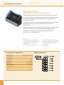
PowerSure® — Ordering Information
How To Specify the Appropriate Model
All model numbers begin with a prefix (IH, IM, IL).
Moving from left to right, choose correct
configuration from each column for your
application. Your completed model number
should look similar to the example below:
PowerSure® High Exposure Model Number : I H 1 2 3 6
PowerSure® Medium Exposure Model Number : I M 1 2 4
PowerSure® Low Exposure Model Number : I L 1 2 5
Example Part Number: IH 120 L 200 4X
1
2
Voltage Code
Phase Configuration
Surge Capacity (High Exposure)
Nominal Voltage Level
Model
Identification
Phase Configuration
Model
Identification
Surge Capacity Per Phase Model
(L-N + L-G)Identification
L–N
L–L
L–G
N/A
120
Single Phase 2 Wires + Gnd (Line & Neutral)
N
120
120
208
120
L
120
240
120
Single Phase 2 Wires + Gnd (Line & Line)
N/A
240
240
240
277
480
277
277
N/A
480
480
480
120
Other voltages available, please consult factory.
Single (Split) Phase S
3 Wires + Gnd
Three Phase Wye 4 Wires + Gnd
Y
Three Phase Delta 3 Wires + Gnd
D
Three Phase Delta Hi-Leg 4 Wires + Gnd
H
Three Phase Wye w/no Neutral 3 Wires + Gnd
X
4
400 kA
L–N
L–G
N–G
200
200
200
L–G
N–G
200
N/A
200
200-2
200 kA
L–N
L–G
N–G
100
100
100
400
200 kA
L–N
200
100 kA
L–N
L–G
N–G
100
N/A
100
5
Surge Capacity (Medium Exposure)
100-2
6
Surge Capacity (Low Exposure)
Options
Surge Capacity Per Phase Model
(L-N + L-G)Identification
Surge Capacity Per Phase Model
(L-N + L-G)Identification
Option Model
Identification
Rotary Disconnect
R
Surge Counter
C
NEMA 3R Enclosure
3R
L–N
80
160 kA
L–G
N–G
80
80
160
L–N
50
100 kA
L–N
L–G
N–G
100
N/A
100
100-2
L–N
25
100 kA
L–G
N–G
50
50
NEMA 4 Enclosure
L–G
N–G
25
25
50
25 kA
L–N
L–G
N–G
N/A
25
Recommended Connections
100
50 kA
25
6
3
25-2
NEMA 4X Enclosure
4
4X
Transient Voltage Surge Suppression
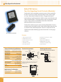
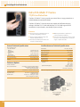
Islatrol® — SP-6TVN
Industrial Strength Surge Suppression (Series)
The Islatrol® SP-6TVN is an industrial-strength surge suppression/filtering device
that plugs into a standard duplex receptacle. It features uniquely designed
repositionable outlets for easy installation behind desks and other furniture.
It protects your sensitive home or office equipment, including TVs, home theaters,
satellite dishes, computers, printers, copiers, and fax machines, from damaging
power disturbances traveling through your wiring into your electrical outlets.
Features
REPOSITIONABLE OUTLETS
■Plugs into standard 120 V, 15 Amp
electrical outlet
■Perfect for tight spaces, behind furniture
and appliances
■Total peak surge current capacity of
39,000 Amps
■Intelligent monitoring against improper
wiring/grounding
■ Cables for telephone, video, and
data connectors
■ 60 dB maximum high frequency
■Repositionable outlets rotate to
accommodate available space
■ 5 year limited warranty
■ Operational indicator lamp
General Technical Specifications
ANSI/IEEE C62.41 Cat A Ringwave (6 kV, 200 A, 100 kHz)
AC Power Protection
Nominal Operating Voltage
Operating Voltage Range
Operating Frequency Range
Rated Output (Amps)
ANSI/IEEE C62.41 Category
Connection Type
Phase Configuration
Size
Enclosure
Weight
Modes Of Protection
Indication of Suppression Status
Response Time
Certifications
Warranty
120 VAC, Single Phase
120 VAC +/- 10%
265 V
Common Mode
290 V
47 – 63 Hz
15 Amperes
Category A & B
(6) 5-15R Receptacles and
5-15P Plug
2 Wire + Gnd
7.5 x 4.75 x 1.75 (Inches)
High Impact Plastic
ANSI/IEEE C62.41 Cat B Ringwave (6 kV, 500 A, 100 kHz)
Normal Mode
275 V
Common Mode
290 V
Frequency Response
Normal Mode
60 dB Maximum, forward/reverse, 100 kHz to 50 MHz
Common Mode
40 dB Maximum, forward/reverse, 5 MHz to 50 MHz
Low Voltage Protection
Video 1 & 2
2.0 lbs (0.9 kgs)
L – N, L – G, N – G
Status Indicator
< .5 ns Normal Mode
UL 1449 Listed
5 Year
130 VAC
Type “F”
Type RJ-11
Type RJ-45
Cables Provided
6' (2x) Type “F” Ends
6' RJ-11 Male Ends
6' RJ-45 Male
Ends
5 kA (8 x 20 µs)
2 kA (10 x 1000 µs)
3 kA
(8 x 20 µs)
Capacitance
Protection Level
Clamping Voltage (DC)
Peak Surge Current (8 x 20 µs)
Line to Neutral
13,000 Amps
Line to Ground
13,000 Amps
Neutral to Ground
13,000 Amps
Total
39,000 Amps
PhoneNetwork
Connection Type
Peak Surge Current
Maximum Continuous Operating Voltage (MCOV)
Line to Neutral
Normal Mode
Attenuation
<12 pf
<50 pf
<70 pf
L-G
T-R, T-G, R-G
L-G (8 Lines)
145 V
270-350 V
30 V
1 dB @ 2 Ghz
N/A
N/A
7
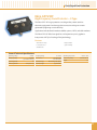
Transient Voltage Surge Suppression
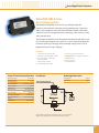
PowerSure® EMC Series
120/240 VAC Heavy Duty (Parallel)
The PowerSure® EMC Series surge suppressor is designed to protect AC
distribution panel circuits or 120 V power supplies feeding sensitive electronic
equipment. Electrically, the unit incorporates MOV and thermal fusing
technology. The PowerSure® EMC Series is designed to be installed in parallel on
standard single or split phase 120/240 VAC circuits.
Features
Operational status indicators
■Fast response time
■UL 1449 listed and OWHX listed
■40,000 Amps per phase capacity
5 year warranty
Failsafe and fused
General Technical Specifications
Part Number
Operating Voltage
120/240 VAC
Clamping Voltage
395 VAC
Operating Current
NA, Parallel
Total Peak Surge Current
Operating Frequency
8
PowerSure® EMC-240B
EMI Attenuation (100 kHz to 100 MHz)
SPD Technology
> 40 dB
Metal Oxide Varistors (MOVs)
Modes of Protection
Line-to-Line,
Line-to-Neutral
80 kA (8 x 20 µs)
Status Indication
Power On & MOVs functional
47–63 Hz
Connection Type
Wire Leads
Fault Current Rating
Operating Temperature
Dimensions (Inches)
Weight
Certifications
42 kAIC
-40°C to +85°C
4.6H x 2.2W x 2.8L
13.5 oz
UL 1449, Suppressor/
OWHX Arrester
Transient Voltage Surge Suppression
PowerSure® TCS-HW Series
Point-of-Application Protection
Utilizing bipolar Silicon Avalanche Diode (SAD) technology, the PowerSure®
TCS-HW Series features a two-stage design that provides superior protection
for sensitive equipment and for ANSI/IEEE C62.41 Location Category
A applications. The PowerSure® TCS-HW Series can be incorporated
into larger power protection or used as point-of-application protection.
Hardwired into a single 15 or 20 amp AC circuit, the PowerSure® TCS-HW
Series places protection at, or near, the critical load. The field-tested design
ensures continuous protection in the most demanding environments, with
configurations available for 120 and 240 VAC, single-phase applications.
Features
■Provides superior, nondegrading protection
using bipolar SAD technology
■Withstands demanding environments with its
rugged metal enclosure
■Provides independent secondary stage for
maximum continued protection
■Installs easily
■Includes remote status indication via RJ-11 jack
■1 year warranty
■ CE listed
■Protects individual circuits
General Technical Specifications
Part Number
PowerSure® TCS-HWD
Part Number
PowerSure® TCS-HWR
Operating Voltage
240 VAC Single Phase
Operating Voltage
120 VAC Single Phase
Clamping Voltage
424 VAC
Clamping Voltage
216 VAC
Operating Current
20A
Operating Current
Total Peak Surge Current
Operating Frequency
48kA
50/60 Hz
Total Peak Surge Current
Operating Frequency
20A
48kA
50/60 Hz
EMI Attenuation
-13dB max
EMI Attenuation
-13dB max
SPD Technology
SAD / MOV / Filter
SPD Technology
SAD / MOV / Filter
Modes of Protection
Status Indication
Connection Type
L-N, L-G, N-G
Power On & MOVs functional, Remote Status
Wire Leads
Modes of Protection
Status Indication
Connection Type
L-N, L-G, N-G
Power On & MOVs functional, Remote Status
Wire Leads
Operating Temperature
-40°C to + 50°C
Operating Temperature
-40°C to + 50°C
Dimensions (Inches)
4H x 4W x 2.5D
Dimensions (Inches)
4H x 4W x 2.5D
Weight
1.25 lb
CertificationsCUL, CE
Weight
1.25 lb
CertificationsCUL, CE
9
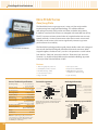
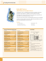
Transient Voltage Surge Suppression
Islatrol® — RM Series
120 VAC Rackmount
This line of AC surge protectors is ideal for protecting the power feeding
valuable rack equipment. All models provide ten protected outlets on
the back and two protected convenience outlets on the front. This series
provides 40,000 Amps of surge protection and up to 60 dB of highfrequency noise filtering. Status LEDs indicate the correct power is coming
to the unit, whether the unit is properly grounded and whether the surge
components are still in tact. Units are available with an optional digital
meter, mounted on the front of the unit, that will monitor the voltage,
current and power of the protected equipment.
Model shown: RM-115-10 RM
Features
■ 4 0 kA surge protection
■ Optional digital meter
■ 60 dB max noise filtering
■ Optional twist lock plug
■ 15 A & 20 A models available
■ 1 year warranty
■P ower, ground and surge status indicators
General Technical Specifications
Part Number
VoltageAmperage Plug (NEMA)Receptacles (NEMA)
Digital MeterLocking Plug
RM-115-10RM
120 V
15 A
5-15P
5-15R
Yes
RM-120-10RM
120 V
20 A
5-20P
5-20R
Yes
No
No
RM-120-10RML
120 V
20 A
L5-20P
5-20R
Yes
Yes
Rackmount AC Power Protection
Rated Voltage
120 V
Rated Current
15 A & 20 A
Peak Surge Current
Response Time
EMI/RFI Filtering
LED Indicators
Digital Meter
(Optional)
10
20 kA/mode, 40 kA/phase
<5 ns
60 dB Max
Green-Power On
Green-Ground OK
Green-Surge Circuit OK
Voltage Amps, Watts, VA, Hz, PF,
Kwh, and Clock
Input Power
15 A Models
SJT 14/3C Power Cord (15 ft)
with NEMA 5-15P Plug
20A Models
SJT 12/3C Power Cord (15 ft)
with NEMA 5-20P Plug
NEMA L5-20P Plug- Optional
Output Receptacles
15 A Models
Front- (2) NEMA 5-15R
Back- (10) NEMA 5-15R
20 A Models
Front- (2) NEMA 5-20R
Back- (10) NEMA 5-20R
Thermal Protection
Over-current Protection
Dimensions
Warranty
Thermal Protected MOVs
Circuit
1.75"H x 19"W x 2.0"D (1U)
1 Year
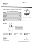
Data/Signal Line Protection
Edco RM-CAT6 Series
CAT6 Channel Rackmount
The Edco RM-CAT6 is a 16-channel high-speed data line protector that utilizes
a three-stage hybrid design technology. This unit addresses high-energy
voltage transients that can damage expensive computer equipment. Ideal
for network switches and hubs, the Edco RM-CAT6 is easily mounted in close
proximity to the protected equipment.
Features
■Exceeds category 6 transmission values
Three stage hybrid
1 year warranty
Compact 1U rack size
Low insertion loss
General Technical Specifications
Part Number
RM-CAT6-16R
Operating Voltage
5V
Clamping Voltage
8.2 V
Frequency Range
0–250 MHz
Operating Current
SPD Technology
Modes of Protection
0.15 A
GDT, SAD, W/Series PTC
Signal High-Low,
Signal High-Ground,
Signal Low-Ground
Peak Surge Current
10 kA (8 x 20 µs)
Insertion Loss
<0.1 dB
VSWR
Operating Humidity
<1.2
Dimensions
1.75Hx19Wx6.3D
Weight
5.5 lbs
Warranty
1 Year
0-95% Non-Condensing
Operating Temperature
-40°C to +85°C
Input Connection Type
RJ-45
Output Connection Type
RJ-45
Mounting
Rackmount
Enclosure Type
Painted Steel
Edco RM-CX06
CCTV Channel Rackmount
The Edco RM-CX06 Surge Protective Device (SPD) is a 16 channel coax
SPD implementing three-stage hybrid technology. The SPD addresses overvoltage transients with a primary Gas Discharge Tube (GDT), and secondary
Silicon Avalanche Diode (SAD) components. Over-current protection, e.g.,
sneak and fault currents, are mitigated with solid-state resettable fuses — PTCs.
The Edco RM-CX06 SPD is designed in accordance with NFPA 780 (2004 edition)
requirements, with up to 20 kA of surge current capability.
Features
Sneak/fault current protection
16 channel
Low insertion loss
1 year warranty
Shielded case
General Technical Specifications
Part Number
Operating Voltage
RM-CX06-16R
Frequency Range
5 VDC
Insertion Loss
Clamping Voltage
6 VDC
SPD Technology
Operating Current
0.15 A
Connection Type
Peak Surge Current
0–100 MHz
< 0.1 dB at 20 MHz
GDT, SAD, w/Series PTC
BNC, 50/75 Ohm
Operating Temperature
Dimensions (Inches)
Weight
Certifications
-40°C to +85°C
1.75H x 19W x 2.0D (1U)
3.2 lbs
UL 497B
20 kA (8 x 20 µs)
11
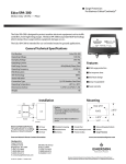
Data/Signal Line Protection
Edco PLP-S Series
Isolated Power Loop Circuit Protection
Using the highest quality Silicon Avalanche Diode (SAD) technology, the Edco
PLP-S Series is designed to protect your equipment from harmful power surges
and transients. Nondegrading SADs will last the lifetime of your equipment,
ensuring system uptime.
The Edco PLP-S Series of products provides isolated power loop circuit protection
in applications where higher current is required, such as fire alarm and
security systems.
Whether incorporated into a larger power protection strategy or used as primary
protection, the Edco PLP-S Series family provides unparalleled protection.
The Edco PLP-S Series keeps your critical equipment online in the most
demanding environmental conditions.
Features
■Silicon Avalanche Diode (SAD) design for
nondegrading performance and protection
■Provides protection for both single and
multiple circuits
■Designed for easy hardwire installation
General Technical Specifications
5, 14, 30, 60, 140, 200 VDC
Clamping Voltage
6, 16, 33, 67, 150, 211 VDC
Peak Surge Current
Frequency Range
Insertion Loss
SPD Technology
Connection Type
0 to 30MHz
< 0.1 dB at 30 MHz
SAD
Terminal Screw
-40°C to +60°C
Dimensions (Inches)
2H x 3W x 1.5D
Certifications
12
7A
400 A
Operating Temperature
Weight
■Provides unparalleled clamping performance
for maximum equipment protection
■UL 497B listed
■1 year warranty
Ordering Information
Operating Voltage
Operating Current
■Rugged enclosure for harsh environments
2.5 oz
UL 497B
PLP-S
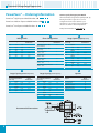
Data/Signal Line Protection
Edco FAS-1 and FAS-2 Series
One and Two Pair Signal Line Protector (Commercial)
The Edco FAS-1 and Edco FAS-2 Series are multi-stage single pair or two pair
surge suppressors designed for high exposure applications. These products were
specifically designed to meet multiple low voltage protection applications in the
fire and security industries.
Features
Lightning protection for low voltage
General Technical Specifications
Operating Voltage
15, 24, 36, 52 VDC
Clamping Voltage
18, 33, 43, 60 VDC
Operating Current
Installation
Ordering Information
U NPROT EC TE D O R FI EL D SI D E
< 0.1 dB at 10 MHz
10– 14 AWG
FAS-1 = 1.5H x 1.5W x 2.8L
FAS-2 = 2H x 2W x 2.8L
FAS-1 = 3.5 oz
24VDC use:
FAS-1-033 HC (single pair)
FAS-2-033 HC (two pair)
24VAC use:
FAS-1-043 HC (single pair)
FAS-2-043 HC (two pair)
*FAS-1-060 HC (single pair)
*FAS-2-060 HC (two pair)
*Not UL Listed
Caution: The hybrid design of this product includes series
resistance. Do not place this product in service on any
signal line capable of continuously supplying more than
2.5 amperes.
-40°C to +85°C
Operating Temperature
FAS-1-018 HC (single pair)
FAS-2-018 HC (two pair)
GRO UND LU G
LI NE .
Terminal block
w/compression lugs
Terminals accept up to 12 AWG
12VDC use:
48V Systems use:
GDT, SAD, w/Series Inductor
EQ U I P.
SPD Technology
Certifications
5 year warranty
0–10 MHz
Insertion Loss
Weight
Automatic recovery
Multi-stage protection
10 kA (8 x 20 µs)
Frequency Range
Dimensions (Inches)
Data/signal lines
2.5 A
Peak Surge Current
Connection Type
Common mode and differential protection mode
<3
FAS-2 = 7 oz
UL 497B
PROTEC T ED EQ UIP.
DO NOT G
daisy
chain Igrounds.
RO UND
N G: NOT intended for
shield termination.
Install
in accordance
1S T CH O ICE:
USE ground
AC P OWER
GRO UND codes.
with all applicable
2N D CH O ICE: USE B U I LDI NG
13
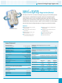
Data/Signal Line Protection
Edco PHC Series
Two-Pair Signaling Circuit Protector (Modular)
The Edco PHC Series is designed to protect two pairs of wires specifically
for alarm and security systems where operating currents can be as high
as 5 Amps. Electrically, the Edco PHC Series is a rugged series hybrid
implementing a staged complement of MOVs, copper wound inductors and
Silicon Avalanche Diodes. This design reduces series resistance to 0.2 Ohms
per pair. These products are intended to mate with an Edco PCB1B
gold-plated female terminal connector.
The Edco PHC modules plug into a base assembly (Edco PCB1B). The base
assembly can be mounted to any flat surface and should be located as close
as practical to the protected equipment. Terminal 1 and/or terminal 10
should be connected to Building-Approved Ground with 12 or 10 gauge
solid wire.
EDCO PCB1B BASE SOLD SEPARATELY
Features
Continuous current up to 5 Amps
Differential protection
UL 497B listed
Common mode protection
Requires Edco PCB1B base
Plug-in module
Automatic recovery
PC642PTU (Pass Thru Unit)
available for troubleshooting
Fast response time
5 year warranty
General Technical Specifications Terminal Assignments
Ordering Information
Operating Voltage
12, 18, 24, 36, 52, 60, 120 VDC
How to Specify the Appropriate Model
Clamping Voltage
15, 20, 30, 43, 60, 70, 150 VDC
Operating Current
5A
Peak Surge Current
Frequency Range
Insertion Loss
SPD Technology
Connection Type
Operating Temperature
Dimensions (Inches)
10 kA (8 x 20 µs)
0–10 MHz
< 0.1 dB at 10 MHz
Terminal block
w/compression lugs
Terminals accept up to 10 AWG
-40°C to +85°C
3.7H x 1.75W x 2.375L
(PHC + PCB1B Base)
Weight
24V Horn, Strobe, Bell:
Unprotected Pair 2
{
Field Side
Unprotected Pair 1
{
Even Terminals
10
9
8
7
6
5
4
3
2
1
PHC-043 & PCB1B
PHC-SP70 & PCB1B
}
Protected Pair 2
Electronics Side 2.125" 2.4"
}
Protected Pair 1
1.0
Ground Terminal 1 or 10 to Building Approved Ground
DO NOT daisy chain grounds. NOT intended for shield
termination. Install ground in accordance with all
applicable codes.
Dimensions
VOLTAGE CLAMP
P H C
Keying Pin
8 oz
UL 497B
Applications Part Number
70V Speaker Lines:
PCB1B:
Odd Terminals
MOV, SAD, w/Series Inductor
Certifications
14
Three-stage protection
0 1 5
15 Volts
0 2 0
20 Volts
0 3 0
30 Volts
0 4 3
43 Volts (For Horn, Bell, Strobes)
0 6 0
60 Volts
S P 7 0
*100 Volts
1 3 0 R M S
*150 Volts
(For 120V Signal Lines)
*Not UL Listed
Data/Signal Line Protection
Edco RJA-RJD Series
RJ-45 Telephone/Data
The Edco RJA and Edco RJD Series are four pair telephone/data line
protectors that implement advanced two stage hybrid design. These units
address over voltage transients with silicon breakover devices, while sneak
and fault currents are mitigated with PTC technology, which consists of solid
state resettable fuses.
The Edco RJA and Edco RJD Series incorporate Edco RJ-45 female jacks in and
out. The Edco RJA voltage clamp is set for C.O. Trunks and Analog Telephone
Extensions (with ring in voltage), and the Edco RJD voltage clamp is set for
Digital Extensions (no ring in voltage).
Features
<1 nanosecond response time
Tip & ring to ground protection
Solid-state resettable fuses — PTCs
CAN/CSA C22.2, No. 226-92 compliant
Silicon breakover technology
UL 497A listed
Low capacitance
4 pair protection
Line-to-line protection
5 year warranty
Accommodates RJ-11 jack
General Technical Specifications Installation
Ordering Information
Operating Voltage
48, 220 VDC
Analog Phone
RJA-45
Clamping Voltage
55, 280 VDC
Digital Phone
RJD-45
Operating Current
Peak Surge Current
Frequency Range
Insertion Loss
SPD Technology
Connection Type
Operating Temperature
Dimensions (Inches)
Weight
Certifications
0.15 A
200 A (10 x 1000 µs)
0–50 MHz
< 0.1 dB at 50 MHz
Silicon Breakover
Devices w/Series PTC
RJ-45 Jacks
-40°C to +85°C
1.0H x 2.5W x 4.25L
3 oz
UL 497A, CUL,
The Edco RJA and Edco RJD Series are intended for indoor use only and shall be
employed on the equipment side of a listed primary telephone protector.
15
Data/Signal Line Protection
Edco H Series
Telecom/Punch Block Protection
Advanced Ultra High Speed Technology
The Edco H-Series modules are ultra high speed fused solid state secondary
protectors for KEY/PABX systems. The units are available in three different
clamping voltages. The Edco H-Series is constructed with solid state silicon
foldback technology, polyswitch resettable fuses — PTCs — and failure fuses.
These protection modules are intended to be used in conjunction with proper
primary protectors (UL 497). The protective elements switch from the normal
high-impedance state to a low-impedance state upon a detection of a surge,
then switch back to high impedance after the surge has passed. The Edco
H-Series single pair modules fit onto a standard Edco MI-50 split block and
replace bridging clips. In addition, these modules require the Edco MGB Ground
Rail for each Edco MI-50 block used.
TTA-2 TEST POINT ADAPTOR
(SOLD SEPARATELY)
General Technical Specifications
Operating Voltage
50, 180, 230 VDC
Clamping Voltage
65, 200, 270 VDC
Operating Current
0.15 A
Peak Surge Current
SPD Technology
0– to 20 MHz
< 0.1 dB at 20 MHz
Silicon Breakover Device
w/ Series PTC
Connection Type
Clip
Operating Temperature
Dimensions (Inches)
Installation
160 A
(10 x 1000 µs T & R to Ground)
Frequency Range
Insertion Loss
TTA-2 Test Point Adaptor
Plugs into test points on HCO, HDE, and HAE, as well as other Edco 66 Block
Protectors. Adaptor is equipped with test clips for connection to telephone test
(butt) set or meter. Order part # TTA-2
-40°C to +85°C
1.25H x 0.4W x 2.8L
Weight
Certifications
1 oz
UL 497A, CUL
Ordering Information
Central Office/Trunks
16
HCO
Analog Extensions
HAE
Digital Extensions
HDE
DO NOT daisy chain grounds. NOT intended for shield termination.
Install ground in accordance with all applicable codes.
Data/Signal Line Protection
Edco COHP Series
Data/Signal Line/Punch Block Protection
High Exposure Applications
The Edco COHP modules are three-stage hybrid protectors for low voltage data and
telecommunications applications. The modules address over-voltage transients with
gas tubes and silicon avalanche components. In addition, sneak and fault currents
are mitigated with resettable fuses (PTCs). Intended to be used on pairs without
the presence of ringing voltage. The Edco COHP modules are designed for data and
control applications as an isolated loop circuit protector.
Features
Replaces bridging clips on MI -50 Block
Rugged three electrode gas tube first stage
<1 nanosecond response time
Silicon avalanche hybrid technology
Line-to-line protection
Polyswitch resettable fusing — PTCs
Line-to-ground protection
5 year warranty
Utilizes MGB grounding rail
Ordering Information
General Technical Specifications
Operating Voltage
6, 12, 24, 43, 52 VDC
SPD Technology
Clamping Voltage
8, 15, 30, 50, 60 VDC
Connection Type
Operating Current
Peak Surge Current
Frequency Range
Insertion Loss
0.15 A
10 kA (8 x 20 µs)
0 to 20 MHz
< 0.1 dB at 20 MHz
Operating Temperature
Dimensions (Inches)
Weight
Certifications
GDT, SAD, w/ Series PTC
COHP-008
8 Volts
Clip
COHP-015
15 Volts
-40°C to +85°C
COHP-030
30 Volts
1.25H x 0.4W x 2.8L
COHP-050
50 Volts
1 oz
COHP-060
60 Volts
UL 497B
17
E
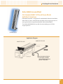
Data/Signal Line Protection
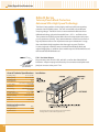
Edco MGB Ground Rail
Fits Standard 66M1-50 Punch Down Blocks
Split Block Variations
Edco MGB Ground Rail — Designed to fit standard 66M1-50 Punch Down Blocks.
Allows Edco’s H-Series, COHP, PB Series and other similar Surge Suppressors to
access ground when snapped onto the 66M1-50 Punch Down Block.
The Standard 66MI-50 block is capable of accommodating up to 25 Edco
surge suppressors.
US PATENT NO. 4,703,983
Application Diagram
PROTECTED SIDE
UNPROTECTED SIDE
Emerson Network Power
recommends a 10AWG
wire to building approved
ground — keep short.
19
Data/Signal Line Protection
Edco PC642 Series
Zone/Loop/Data
The Edco PC642 Series surge suppressor is a two-pair (four-wire) module
implementing three-stage hybrid technology. This module addresses
over-voltage transients with gas tubes and silicon avalanche components.
In addition, sneak and fault currents are mitigated with resettable fuses (PTCs).
The PTCs increase resistance several orders of magnitude when over-currents
exceed safe levels. A normal state resumes when over-currents are removed.
The ability to self-restore in this manner significantly increases suppressor
performance and survivability.
The Edco PC642 card edge module is gold-plated, double-sided, and is designed
to mate with the Edco PCB1B gold-plated female terminal connector. When
snapped together, the data circuits “pass thru” the protector in a serial fashion
from the four “Field Side” terminals to the four “Electronics Side” terminals.
Terminals 1 or 10 of the Edco PCB1B must be attached to Building-Approved
Ground per Edco Technical Bulletin # 2015.
EDCO PCB1B BASE SOLD SEPARATELY
Features
General Technical Specifications
Operating Voltage
8, 15, 20, 30, 36, 43,
50, 60, 200 VDC
Operating Current
0.15 A
Peak Surge Current
10 kA (8 x 20 µs)
Frequency Range
< 0.1 dB at 20 MHz
SPD Technology
GDT, SAD, w/Series PTC
Terminal block
w/compression lugs
Terminals accept up to 10 AWG
Operating Temperature
Dimensions (Inches)
Certifications
-40°C to +85°C
2H x 1W x 2.5L
(PC642 + PCB1B Base)
1 oz
UL 497B
Caution: The hybrid design of this product includes
series resistance. Do not place this product in service
on any signal line capable of supplying more than
150 milliamperes continuously.
20
Requires Edco PCB1B base
Resettable fusing — PTCs
Low capacitance option
PC642PTU (Pass Thru Unit)
available for troubleshooting
Plug-in module
5 year warranty
Terminal Assignments
Ordering Information
PCB1B:
Odd Terminals
Unprotected Pair 2
{
Field Side
Unprotected Pair 1
{
APPLICATION:
Even Terminals
10
9
8
7
6
5
4
3
2
1
0 to 20 MHz
Insertion Loss
Weight
Fast response time
5, 12, 18, 24, 30, 36,
43, 52, 180 VDC
Clamping Voltage
Connection Type
Three-stage hybrid protection
Sneak/fault current protection
}
RS485, RS422:
PC642
RS232:
Protected Pair 2
PC642C-020 & PCB1B
E-NET, 10 BASE T:
Electronics Side 2.125" 2.4"
}
PC642C-008LC & PCB1B
RS423, Token Ring: PC642C-008LC & PCB1B
4–20ma:
Protected Pair 1
PC642C-030LC & PCB1B
PC642C-036 & PCB1B
Keying Pin
1.0
PCB1B
Ground Terminal 1 or 10 to Building Approved Ground
DO NOT daisy chain grounds. NOT intended for shield
termination. Install ground in accordance with all
applicable codes.
How to Specify the Appropriate Model
PC642C VOLTAGE CLAMP
8 Volts
15 Volts
20 Volts
30 Volts
36 Volts
43 Volts
50 Volts
60 Volts
*200 Volts
•Not UL Listed
0
0
0
0
0
0
0
0
2
0
1
2
3
3
4
5
6
0
8
5
0
0
6
3
0
0
0
D
X
LC
no suffix
stage 2 clamp
each line-to-ground
stage 2 clamp
line-to-line only
stage 2 clamp line-to-line
and each line to ground
low capacitance option stage
2 clamp line-to-line and each
line to ground
Data/Signal Line Protection
Edco PC642PTU
Pass Thru Unit
The Edco PC642PTU is an invaluable tool for troubleshooting Edco card-edgestyle protectors (PC642, PC2TEL, PHC, SLCP Series).
Simply unplug the existing Edco card-edge-style protector and plug the Edco
PC642PTU (Pass Thru Unit) into the Edco PCB1B base of the circuit to be tested.
The Edco PC642PTU will provide continuity to your circuit, thus eliminating the
need for a two-man crew or to rewire your circuit for troubleshooting purposes.
Installation Diagram
PCB1B:
Odd Terminals
{
Unprotected Pair 2
Field Side
{
Unprotected Pair 1
NOTE – The Edco PC642PTU is NOT a surge protector. Proper
surge protection must be reinstalled on the circuit.
Even Terminals
10
9
8
7
6
5
4
3
2
1
}
DO NOT daisy chain grounds. NOT intended for shield/drain
wire termination.
Protected Pair 2
Electronics Side 2.125" 2.4"
}
Install ground in accordance with all applicable codes.
The Edco PCB1B base sold separately.
Protected Pair 1
Keying Pin
1.0
Ground Terminal 1 or 10 to Building Approved Ground
Edco CAT6-5 POE
CAT6/CAT5 Power Over Ethernet
The Edco CAT6-5 POE Series is designed to work on Category 5 PowerOver-Ethernet transmission lines as well as Category 6 applications. Ideal
to protect expensive equipment against surges and transients entering a
building on exposed transmission lines. Available in both female to female
and male to female RJ-45 connectors.
Features
■ E xceeds CAT5 & 6 transmission values
■ A pplications up to 60 VDC @ 300 mA
■ C AT5 POE compatible
■ 1 year warranty
■ C AT6 compatible
Ordering Information
General Technical Specifications
Operating Voltage
60 VDC
Connection Type
Clamping Voltage
65 VDC
Operating Temperature
Operating Current
300 mA
Dimensions (Inches)
Peak Surge Current
Frequency Range
Insertion Loss
60 A (10 x 1000 µs)
0–250MHz
Weight
RJ-45 Jacks
RJ-45 (FF) CAT6-5POE-FF
-40°C to +85°C
RJ-45 (MF)
CAT6-5POE-MF
0.8H x 1.0W x 2.3L (FF)
0.8H x 1.0W x 3.0L (MF)
1 oz
< 0.1 dB at 20 MHz
SPD Technology Silicon Avalanche Diode (SAD
21
Data/Signal Line Protection
Edco LCDP Series
Data Circuit Protection
The Edco LCDP Series is designed to conveniently protect 8 wire, low voltage data
circuits and employs two RJ-45 jacks for easy installation. The Edco LCDP utilizes
silicon avalanche (solid-state) suppression technology, and exhibits very low
capacitance to accommodate high data rates. This unit supports high-speed data
rates of over 100 Mbps.
Features
<1 nanosecond response time
Silicon avalanche design
Line-to-line protection
Line to ground protection
Low capacitance
5 year warranty
RJ-45/4 pair protection (8 wire)
Installation
General Technical Specifications
Operating Voltage
5, 12, 24, 48, 65 VDC
Clamping Voltage
8, 15, 30, 60, 75 VDC
Operating Current
Peak Surge Current (10 x 1000 µs)
Frequency Range
Insertion Loss
SPD Technology
Connection Type
Operating Temperature
Dimensions (Inches)
Weight
Certifications
22
1.5 A
008 = 125 A, 015 = 72 A,
030 = 22 A, 060 = 18 A, POE*=15 A
0—100 MHz
< 0.1 dB at 50 MHz
Silicon Avalanche Diode (SAD)
RJ-45 Jacks
-40°C to +85°C
1.0H x 2.5W x 4.25L
3 oz
UL 497B (*except LCDP-POE)
The user equipment plugs into the LCDP’s equipment (protected) side,
and the LCDP’s line (unprotected) side is connected to the incoming line.
All 8 conductors are protected. The green ground wire must be bonded
to the protected equipment power ground (third wire, green wire safety
ground). Do not add length to the ground wire, for it must be kept as
short as possible.
Ordering Information
LCDP-008
8 Volts
LCDP-015
15 Volts
LCDP-030
30 Volts
LCDP-060
60 Volts
LCDP-POE
75 Volts
Data/Signal Line Protection
Edco TCS-T1 Series
T1 Line Protection Against Damaging Transients
Protection of your vital T1 lines should be part of the overall power protection plan
for your facility. The Edco TCS-T1 Series provides you state-of-the-art protection in
a small package.
T1 lines need protection from direct and indirect lightning, as well as power
disturbances from nearby AC lines. The Edco TCS-T1 Series prevents T1 line
disturbances by providing a level of protection typically not provided by the
telephone company.
The Edco TCS-T1 Series devices combine highly reliable, nondegrading Silicon
Avalanche Diode (SAD) technology, along with high energy gas tube protection.
This technology combination leverages the best aspects of each protection
method in a single, reliable design to ensure optimal performance.
The Edco TCS-T1 Series features two models with different clamping voltages.
Both the Edco TCS-T1S and the Edco TCS-T1DS support in-line connections via
hardwire lugs or standard RJ-45 ports.
Features
Uses bipolar Silicon Avalanche Diode to
provide nondegrading protection
Provides unparalleled performance in a
compact, modular design
Comes complete with ring terminals
and a male/male RJ-45 cable to make
installation easy
1 year warranty
Offers RJ or hardwire connection
capabilities to provide installation flexibility
General Technical Specifications
Part Number
Edco TCS-T1S
Part Number
Edco TCS-T1DS
Operating Voltage
170 VDC
Operating Voltage
8 VDC
Clamping Voltage
211 VDC
Clamping Voltage
13 VDC
1A
Operating Current
Operating Current
Total Peak Surge Current*
Frequency Range
Insertion Loss
SPD Technology
Connection Type
40,000 A
0 to 55MHz
< 0.1 dB at 55 MHz
SAD / GDT
Hardwire Lugs or RJ-45
Total Peak Surge Current*
Frequency Range
Insertion Loss
SPD Technology
Connection Type
1A
40,000 A
0 to 55MHz
< 0.1 dB at 55 MHz
SAD / GDT
Hardwire Lugs or RJ-45
Operating Temperature
-40°C to +85°C
Operating Temperature
-40°C to +85°C
Dimensions (Inches)
2H x 3W x 1.5D
Dimensions (Inches)
2H x 3W x 1.5D
Weight
Certifications
5 oz
UL 497B
Weight
Certifications
5 oz
UL 497B
*Based on component specifications for all T1 lines.
23
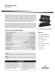
Data/Signal Line Protection
Edco TCS-Multi T1 Series
T1/E1 Line Protection
The Edco TCS-Multi T1 Series provides you state-of-the-art surge protection in a
scalable backplane connected solution.
The Edco TCS-Multi T1 Series features two models with different clamping
voltages, the Edco TCS-T1S-MX and the Edco TCS-T1DS-MX support in-line
connections via 4 pin headers, standard RJ-45 ports or both.
Features
■U ses bipolar Silicon Avalanche Diode to
provide nondegrading protection
■O ffers RJ and hardwire capabilities to
provide installation flexibility
■P rotects against lightning surges and
internal transient activity
■E nclosure can be mounted as a telco mount
(vertical or horizontal) and 19" rack mount
single or double enclosure
■P rovides unparalleled performance in a
compact, modular design
General Technical Specifications
Card Performance Technical Specifications
Enclosure Dimensions:
Telco Board Mount
(Inches) (Centimeters)
19" Rackmount
(Inches)
(Centimeters)
Part Number
Primary Technology
1.75H x 8.5W x 5.5D
4.4H x 21.6W x 14D
Operating Frequency
1.75H x 19W x 5.5D
4.4H x 48.3W x 14D
Clamping Voltage Silicon Avalanche Diode
Peak Pulse Current
Nominal Current Interface RJ-45 and hardwire
Leak Capacitance 19" Rackmounting
Single Enclosure
Dual Enclosure 2000048-00 — Enclosure with backplane
and brackets, holds up to 6 cards
Comes with 4 cards installed
2000052-00 — Enclosure without cards
Up to 8 Vpk
13 Vpk
Response Time Gas Discharge Tube
Telco Board Mount
Enclosure Part Number Up to 55 MHz
Signal Line Voltage
Secondary Technology
Enclosure Options
.
Edco TCS-T1DS-M2
5 ns or less
10kA*
4,000 Amp
38 Picofarad
Protection Modes:
Hardwire RJ-48C Standard (RJ-45)
L1-G – L3-G
L2-G – L4-G
L1-L2 – L3-L4
Pin 1-G – Pin 4-G
Pin 2-G – Pin 5-G
Pin 1-Pin 2 – Pin 4-Pin 5
* Based on component specifications (8 x 20 µs)
2000049-00 — Mounting bracket,
holds up to 6 cards
2000050-00 — holds up to 12 cards
Other configurations available
TCS-T1S/T1DS-M2
HARD CONNECT
AND RJ
24
Data/Signal Line Protection
Edco DCB Series
DC Power Protection for Critical Equipment
DC powered equipment is susceptible to transient events that may pass from
the AC, Telco, or Coax services to the equipment directly or through other
equipment. Harmful transients found in all power services can cause costly
damage and downtime of vital DC powered equipment.
In response to this problem, the Edco DCB Series for state-of-the-art surge
protection was created to fit various application needs. The Edco DCB Series is
available in 24 or 48 VDC configurations, and mounts to an equipment chassis.
Its compact size makes the Edco DCB easy to install, even in the tightest spaces.
Alone, or as part of your overall power protection strategy, the Edco DCB
Series protects and provides unparalleled performance in power protection for
critical equipment.
Features
■B ipolar Silicon Avalanche Diode technology
provides fast, nondegrading protection
■M etal Oxide Varistors provide a “second
stage” of power protection
■C ompact module designed to fit tight
spaces where DC power protection
is needed
■1 year warranty
■I deal protection for radios, channel banks,
rectifiers, inverters, converters and various
other DC powered equipment
General Technical Specifications
Part Number
Edco DCB-24S & DCB-24SM
Part Number
Edco DCB-48
Operating Voltage
24 VDC
Operating Voltage
48 VDC
Clamping Voltage
31 VDC
Clamping Voltage
83 VDC
Operating Current
150A
Operating Current
Total Peak Surge Current
Frequency Range
Insertion Loss
SPD Technology
Connection Type
Operating Temperature
Dimensions (Inches)
Weight
17,000A
0 to 55 MHz
< 0.1 dB at 55 MHz
SAD / MOV
Standard Lug (S) Mini Lug (M)
-40°C to +60°C
2.8H x 5.2W x 2D
12 oz
Total Peak Surge Current
Frequency Range
Insertion Loss
SPD Technology
Connection Type
Operating Temperature
Dimensions (Inches)
Weight
150 A
52,000A
0 to 55 MHz
< 0.1 dB at 55 MHz
SAD / MOV
Standard Lug (S) Mini Lug (M)
-40°C to +60°C
3.1H x 5.25W x 2.4D
12 oz
25
Data/Signal Line Protection
Edco CCTV-1
Closed Circuit TV Protection
The Edco CCTV-1 application is specifically designed for lightning protection on
closed circuit TV systems. The protector is easily installed with standard type BNC
coax connectors. The Edco CCTV-1 offers low loss even at frequencies approaching
500 Mhz. This is important for error-free data communication applications.
Features
Automatic recovery
Shielded case
Low insertion loss
Miniature size
Easily installed
5 year warranty
General Technical Specifications
Operating Voltage
5 VDC
Clamping Voltage
90 VDC (Spark Over Voltage)
Operating Current
1A
Peak Surge Current
Frequency Range
10 kA (8 x 20 µs)
0 to 1 GHz
Insertion Loss
SPD Technology
< 0.5 dB at 500 MHz
<1.0 dB at 900 MHz
Dimensions (Inches)
0.6H x 0.6W x 2.0L
Weight
1 oz
Gas Discharge Tube (GDT)
Connection Type
BNC, 75 Ohm
Operating Temperature
-40°C to +85°C
Edco CX Series
CCTV High Exposure
The Edco CX06-M & Edco CX06-MI Surge Protective Devices (SPDs)
implement three-stage hybrid technology. The SPDs address over-voltage
transients with a primary Gas Discharge Tube (GDT), and secondary Silicon
Avalanche Diode (SAD) components. Over-current protection, e.g. sneak
and fault currents, are mitigated with solid-state resettable fuses — PTCs.
The Edco CX06-M & Edco CX06-MI SPDs are designed in accordance with
NFPA 780 (2004 edition) requirements, with up to 20 kA of surge current
capability. The Edco CX06-MI model has an isolated ground and is
recommended for use at the camera end.
Features
Sneak/fault current protection
CX06-MI has an isolated ground
Low insertion loss
5 year warranty
Shielded case
General Technical Specifications
Operating Voltage
5 VDC
Connection Type
Clamping Voltage
6 VDC
Operating Temperature
0.15 A
Dimensions (Inches)
Operating Current
Peak Surge Current
Frequency Range
Insertion Loss
SPD Technology
26
Ordering Information
20 kA (8 x 20 µs)
0– 20 MHz
< 0.1 dB at 20 MHz
GDT, SAD, w/Series PTC
Weight
Certifications
BNC, 50/75 Ohm
-40°C to +85°C
M = 1.5H x 1W x 3.25L
MI = 1.5H x 1W x 4L
M = 2.3 oz MI = 3 oz
UL 497B
Head End
CX06-M
Camera End
CX06-MI
Data/Signal Line Protection
Edco CATV-DF
High Frequency Coax Protector — F-Type
The Edco CATV–DF surge protectors are designed to protect sensitive
electronic equipment from damage due to excessive voltage or currents
generated by lightning or static build-up.
Applications include direct broadcast satellite systems, HDTV, and cable modems.
The Edco CATV-DF offers low signal loss at frequencies up to 2 gigahertz.
Incorporates GDT (Gas Discharge Tube) technology.
Features
Automatic recovery
Easily installed
Low insertion loss
5 year warranty
Shielded case
General Technical Specifications
Operating Voltage
25 VDC
Clamping Voltage
150 VDC
(Spark Over Voltage)
Operating Current
1A
Peak Surge Current
10 kA (8 x 20 µs)
Frequency Range
Insertion Loss
SPD Technology
Connection Type
0 to 2 GHz
< 1.0 dB at 1 GHz
< 2.0 dB at 2 GHz
Operating Temperature
Dimensions (Inches)
Weight
-40°C to +85°C
1.25H x 2.5W x 4L
3 oz
Gas Discharge Tube (GDT)
Type F Female
27
Data/Signal Line Protection
Edco NET Series
SIECOR Network Interface Device
The Edco NET Series is a SIECOR Network Interface Line Module with built-in
secondary surge protection. In addition to silicon breakover clamping
technology (over-voltage), the Edco NET Series incorporates state-of-the-art
resettable over-current protection devices — PTCs.
The over-current circuitry allows normal telephone currents to pass, but quickly
switches to a high impedance state when subjected to extended over-currents
that can damage telephone system line cards.
Features
Tip to ring protection
Resettable fusing — PTCs
Tip, ring to ground protection
UL 497A listed
Solid state over-current protection
5 year warranty
General Technical Specifications
Part Number
Part Number
Edco NET-060T
Max. Peak Signal Voltage
12
Max. Peak Signal Voltage
52
Nominal Breakdown Voltage
15
Nominal Breakdown Voltage
60
Max Peak Pulse Current
Ip 10 X 1000 µs
Typ Cap (pf)
Max Continuous Current
Nominal Series Resistance
Part Number
124
2100
150ma
8 Ohms
Edco NET-030T
Max Peak Pulse Current
Ip 10 X 1000 µs
Typ Cap (pf)
Max Continuous Current
Nominal Series Resistance
Part Number
36
750
150ma
8 Ohms
Edco NET-200T
Max. Peak Signal Voltage
24
Max. Peak Signal Voltage
180
Nominal Breakdown Voltage
30
Nominal Breakdown Voltage
230
71
Max Peak Pulse Current
Ip 10 X 1000 µs
Max Peak Pulse Current
Ip 10 X 1000 µs
Typ Cap (pf)
Max Continuous Current
Nominal Series Resistance
Part Number
1180
150ma
8 Ohms
Edco NET-050T
Typ Cap (pf)
Max Continuous Current
Nominal Series Resistance
Part Number
200A (T-G)+ (R-G)
150
150ma
8 Ohms
Edco NET-TEL
Max. Peak Signal Voltage
43
Max. Peak Signal Voltage
220
Nominal Breakdown Voltage
50
Nominal Breakdown Voltage
270
Max Peak Pulse Current
Ip 10 X 1000 µs
45
Max Peak Pulse Current
Ip 10 X 1000 µs
Typ Cap (pf)
Max Continuous Current
Nominal Series Resistance
30
Edco NET-015T
Installation
900
150ma
8 Ohms
Typ Cap (pf)
Max Continuous Current
Nominal Series Resistance
200A (T-G)+ (R-G)
150
150ma
8 Ohms
Notes:
A. Never install telephone wiring during a
lightning storm.
B. Protectors are intended for indoor or outdoor
use within a network interface device
(Siecor CAC 7600).
C. If any visible damage has occurred to module,
turn off power before attempting to remove or
insert another module.
D. Install in accordance with the NEC, Article 800.
Data/Signal Line Protection
Edco FAS-TEL and FAS-31XT
RJ11/RJ31X Telephone Protection
The Edco FAS-TEL and Edco FAS-31XT are single pair telephone or data line
protectors that implement advanced two-stage hybrid design. These units
address over-voltage transients with silicon breakover devices, while sneak
and fault currents are mitigated with PTC technology which consists of solid
state resettable fuses.
The Edco FAS-31XT replaces the RJ31X jack with a protected version. Four
screw terminals are provided to wire the protector in the same manner as a
standard RJ31X jack.
The Edco FAS-TEL is nearly identical to the Edco FAS-31XT except without
the shorting bars. Two screw terminals are provided to connect Telco Line to
protector. Protected equipment such as modems are plugged into female
modular jack on the Edco FAS-TEL.
Features
<1 nanosecond response time
Line-to-line protection
Solid-state silicon breakover technology
Line-to-ground protection
Low capacitance
Polyswitch resettable fuses — PTCs
Over-current protection
5 year warranty
UL 497A listed
General Technical Specifications
Operating Voltage
43, 52, 220, & 220 VDC
Clamping Voltage
50, 60, 270, & 270 VDC
Operating Current
0.15 A
Peak Surge Current
160 A
(10 x 1000 µs T & R to Ground)
Frequency Range
0 to 20 MHz
Insertion Loss
SPD Technology
Connection Type
Installation
< 0.1 dB at 20 MHz
Silicon Avalanche Diode
w/ Series PTC
Terminal block
with compression lugs IN /
RJ connector OUT
Operating Temperature
Dimensions (Inches)
Weight
Certifications
-40°C to +85°C
1H x 2W x 2L
2 oz
UL 497A, CUL
Ordering Information
Digital Phone
FAS-TEL-060T
Analog Phone/Fax/Modem/DSL
FAS-TEL-200T
Alarm System Phone
FAS-31XT
31
E