1
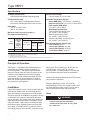
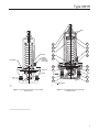
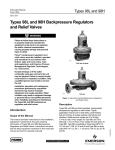
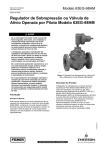
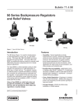
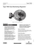
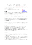
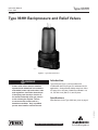
Type 98HH
Instruction Manual
Form 1930
June 2008
Type 98HH Backpressure and Relief Valves
W2592-1
Figure 1. Type 98HH Relief Valve
!
Introduction
Warning
Fisher® relief valves must be installed,
operated, and maintained in accordance
with federal, state, and local codes, rules
and regulations, and Fisher instructions.
Specifications
Specifications for the Type 98HH are given on page 2.
D100706X012
If the spring case develops a leak or if
the outlet continually vents gas, service
to the unit may be required. Failure
to correct trouble could result in a
hazardous condition. Only a qualified
person must install or service the unit.
Type 98HH (see Figure 1) valve provides relief
or differential relief in liquid, gas, air, and steam service
applications. Outlet pressure settings range from 150 to
375 psig (10,3 to 25,9 bar). Bodies are available in 1/4,
1/2, 3/4, and 1-inch (DN 15, 20, and 25) sizes.
www.emersonprocess.com/regulators
Type 98HH
Specifications
Available Constructions
Self-operated with standard adjusting screw.
Relief Pressure Range
150 to 375 psig (10,3 to 25,9 bar)
End Connection Style
NPT, socket weld, or ANSI flanged-14-inches
face-to-face (DIN flanged-356 mm face-to-face)
Allowable Temperature Ranges(5)
Body Sizes
1/4, 1/2, 3/4, and 1-inch
(DN 15, 20, and 25)
Maximum Inlet Pressures, Psig (bar)(1,5)
(Set Pressure Plus Build up)
type
number
steel
(wcC) or
stainless
steel
spring
case all
trims to
150°f(2) (66°C)
98HH
400 (27,6)
cast iron spring case
Metal Trims(4)
All Trims to
150°F(3) (66°C)
400 (27,6)
To 315°F
(157°C)
To 406°F
(208°C)
300 (20,7)
250 (17,2)
Nitrile (NBR) Parts: -20° to 200°F (-29 to 93°C)
Neoprene (CR) Parts: -40° to 150°F (-40 to 66°C)
Fluorocarbon (FKM) Parts:
0° to 300°F (-18° to 149°C)
Metal Diaphragm and Seat
Cast Iron Body and Spring Case:
-40° to 406°F (-40° to 208°C)
Steel Body and Spring Case:
-20° to 450°F (-29° to 232°C)
Stainless Steel Body and Spring Case:
-40° to 450°F (-40° to 232°C)
Approximate Weights, Pounds (kg)
1/4-inch Body: 8 (3,63)
1/2-inch (DN 15) Body: 8 (3,63)
3/4-inch (DN 20) Body: 20 (9,07)
1-inch (DN 25) Body: 20 (9,07)
1. Relief pressure setting plus maximum allowable buildup over setting.
2. Or fluorocarbon trims to 300°F (149°C) or metal trims to 450°F (232°C).
3. Or fluorocarbon trims to 300°F (149°C).
4. Interpolate for intermediate pressure ratings.
5. The pressure/temperature limits in this manual and any applicable standard limitation should not be exceeded.
Principle of Operation
See Figure 2. Type 98HH relief and backpressure
valves relieves excessive pressures upstream of
the main regulator. If the upstream pressure rises
above the setting of the relief valve, pressure on the
underside of the diaphragm overcomes the spring
compression. The valve plug moves away from the
orifice and allows the excess pressure to escape.
When the upstream pressure returns to normal, the
plug resumes a closed position.
Installation
Unbox and inspect the valve. Remove pipe scale and
other foreign material from the connecting pipeline.
Apply a suitable pipe compound to the male threads.
The relief valve can be installed in any position as long
as the flow is in the direction indicated by the arrow
cast on the body. The design of the valve isolates the
diaphragm and pressure response chamber from the
main flow stream. High pressure is measured inside
the body through a registration hole on the inlet side
of the body. If loading pressure is required, connect
the loading pressure line to the NPT connection in the
2
spring case. This connection is 1/8-inch NPT for
1/4-inch bodies, 1/4-inch NPT for 1/2-inch
(DN 15) bodies. If loading pressure is not required,
this connection should be vented to atmosphere.
Maximum operating temperatures for the Type 98HH
relief valves are as follows:
Elastomer diaphragm or seat: 150°F (66°C)
Metal diaphragm or seat: 406°F (208°C) with a cast
iron body and spring case or 450°F (232°C) with a
steel or stainless steel body and spring case.
Vents
!
Warning
If the process fluid is hazardous,
install remote vent lines to carry fluid
to a safe area.
Type 98HH
If remote venting is necessary, install a remote vent
line in the spring case and outlet connections of
Type 98HH relief valve. The vent lines must have the
largest practical diameter and be as short as possible
with a minimum number of bends or elbows.
Overpressure
!
Warning
Overpressuring any portion of this
equipment may cause equipment
damage, leaks in the relief valve,
or personal injury due to bursting
of pressure-containing parts. The
system should be inspected after any
overpressure condition.
Relief pressure settings range from 150 to 375 psig
(10,3 to 25,9 bar).
Adjustment
Each unit is factory set for the pressure setting
specified on the order. If adjustment is necessary,
use a pressure gauge to monitor the pressure. Turn
the adjusting screw (key 15) clockwise to increase the
pressure or differential pressure setting. To decrease
the setting, turn the adjusting screw counterclockwise.
Maintenance
!
Warning
To avoid personal injury and
equipment damage, isolate the valve
from all pressure. Cautiously release
pressure from the relief valve before
attempting disassembly.
Due to normal wear and damage that may occur from
external sources, relief valve parts such as the O-rings,
gaskets, diaphragm, orifice, and valve plug should be
inspected periodically and replaced as necessary. The
frequency of inspection and replacement depends upon
the severity of service conditions or the requirements of
state and federal laws.
Instructions are given below for disassembly of the
Type 98HH relief and backpressure valves. These
valves do not have to be removed from the pipeline to
inspect internal parts. Suitable lubricants are indicated
on the assembly drawings. Apply the lubricants as the
relief valve is being reassembled. Refer to Figure 3
while servicing the relief valve.
Disassembly to Replace Diaphragm
and Seats
If the relief valve is leaking, the diaphragm may be
ruptured or the seating surfaces nicked or scratched.
Proceed as follows to replace or repair the diaphragm,
orifice, and valve plug.
1. Release all spring compression from the
diaphragm by turning the adjusting screw
(key 15) counterclockwise.
2. Remove cap screws (key 16) and lift off the spring
case (key 2), spring (key 11), upper spring seat
(key 9) and diaphragm assembly. (The diaphragm
assembly includes the locknut, key 26; pusher
post, key 6; lock washer, key 23; lower spring
seat, key 8; diaphragm, key 12; gasket, key 10;
washer, key 7).
Note
There are two diaphragms if the
diaphragm material is metal
or fluorocarbon.
3. Check the orifice (key 3). If it needs replacing or
repairing, unscrew the valve plug guide (key 5)
and then the orifice. The valve plug can be
removed by sliding it off of the pusher post.
Note
If damage to elastomer or metal seating
surfaces is severe, replace the orifice
and valve plug O-ring with new parts.
However, by following the lapping
procedure below, it is possible to repair
metal seating surfaces if they are only
slightly worn or scratched.
3
Type 98HH
4. Lapping procedure:
Parts Ordering
a. Place a small amount of 500-grit silicon carbide
or aluminum oxide lapping compound on a flat
surface such as a piece of heavy plate glass.
When corresponding with your local Sales Office about
this equipment, be sure to include the type number
and other information stamped on the nameplate.
b. Take the valve plug or orifice and move it in a
Figure 8 motion on the lapping compound. Do not
allow the part to tip or rock since this would round
the corners.
When ordering replacement parts, reference the key
number each needed part and specify the elevencharacter part number as found in the following parts list.
c. Repeat step b for each part, using an
800-grit or 1000-grit silicon carbide or aluminum
oxide lapping compound.
Parts List
d. Wash away all traces of the lapping compound.
To help prevent scratching the seating surfaces,
a light coat of oil may be applied before returning
the valve plug and the ring to the body.
5. Return the orifice and valve plug guide to the body.
6. To replace the valve plug O-ring (key 22),
remove the screw (key 24) and O-ring retainer
(key 21) from the plug. Remove and replace the
spring O-ring.
7. Remove the locknut from the pusher post in order
to separate the parts of the diaphragm assembly.
Inspect, and replace if necessary, the diaphragm,
diaphragm gasket (key 19), and pusher post
gaskets (key 10).
Note
These valve have either a metal or
elastomer diaphragm. If a metal
diaphragm is to be replaced with an
elastomer diaphragm or an elastomer
diaphragm with a metal diaphragm, a
new pusher post is required.
8. Slip the plug back onto the pusher post and
return the rest of the diaphragm assembly parts
to the pusher post in the following order: gasket,
diaphragm, O-ring, lower spring seat, and
washer. Screw on the locknut.
9. Place the diaphragm gasket on the body and put
the diaphragm assembly into position in the body.
10. Set the spring and upper spring seat over the
lower spring seat. Place the upper casing on the
body, tightening the cap screws finger-tight only.
11. To ensure proper slack in the diaphragm, apply
some spring compression by turning the adjusting
screw clockwise. Tighten the cap screws.
4
Key Description
Part Number
Parts kit (included are keys 3, 4, 10, 12,
19, 21, 22 and 24)
Elastomer Trim
1/4-inch body
1/2-inch (DN 15) body
3/4 and 1-inch (DN 20 and 25) bodies
Metal Trim
1/4-inch body
1/2-inch (DN 15) body
3/4 and 1-inch (DN 20 and 25) bodies
1
Body
Cast iron
1/4-inch NPT
1/2-inch NPT
3/4-inch NPT
1-inch NPT
Steel
1/4-inch NPT
1/2-inch NPT
3/4-inch NPT
1-inch NPT
316 stainless steel
1/4-inch NPT
1/2-inch NPT
3/4-inch NPT
1-inch NPT
2
Spring Case
Cast iron
1/4-inch body
1/2-inch (DN 15) body
3/4 and 1-inch (DN 20 and 25) bodies
Steel
1/4-inch body
1/2-inch (DN 15) body
3/4 and 1-inch (DN 20 and 25) bodies
3* Orifice
Metal to metal seat
416 stainless steel
1/4-inch body
1/2-inch (DN 15) body
3/4 and 1-inch (DN 20 and 25) bodies
*Recommended spare part.
R98HX000012
R98HX000022
R98HX000032
R98HX000042
R98HX000052
R98HX000062
1L346419012
2L339519012
2L342519012
2L342619012
1L372122012
2L368722012
2L373422012
2L373522012
1L372133092
2L368733092
2L373433092
2L373533092
2P181922012
2P182122012
3P182422012
2P181922012
2P182122012
3P182422012
1E391646172
1E395046172
1E398046172
Type 98HH
N.S.
diaphragm
15
9
17
2
11
23
spring
26
8
loading
pressure
connection
(type 98HHD)
16
12
METAL
valve plug
19
METAL
10
6
N.S.
orifice
5
4
N.S.
3
N.S.
CN9433
A1788-1
1
NEVER SEEZ
(1)
30A7036-A
Figure 2. Operational Schematic for Type 98HH
Relief Valves
Figure 3. Type 98HH Relief Valve Assembly
with Metal Seals
1. Never-Seez mark owned by Never-Seez Corp.
5
Type 98HH
Key Description
3* Orifice (continued)
Metal to metal seat
316 stainless steel
1/4-inch body
1/2-inch (DN 15) body
3/4 and 1-inch (DN 20 and 25) bodies
Elastomer Seat
416 stainless steel
1/4-inch body
1/2-inch (DN 15) body
3/4 and 1-inch (DN 20 and 25) bodies
316 stainless steel
1/4-inch body
1/2-inch (DN 15) body
3/4 and 1-inch (DN 20 and 25) bodies
4* Valve Plug
Metal to metal seat
416 stainless steel
1/4-inch body
1/2-inch (DN 15) body
3/4 and 1-inch (DN 20 and 25) bodies
316 stainless steel
1/4-inch body
1/2-inch (DN 15) body
3/4 and 1-inch (DN 20 and 25) bodies
Elastomer Seat
416 stainless steel
1/4-inch body
1/2-inch (DN 15) body
3/4 and 1-inch (DN 20 and 25) bodies
316 stainless steel
1/4-inch body
1/2-inch (DN 15) body
3/4 and 1-inch (DN 20 and 25) bodies
5
Valve Plug Guide
416 stainless steel
1/4-inch body
1/2-inch (DN 15) body
3/4 and 1-inch (DN 20 and 25) bodies
316 stainless steel
1/4-inch body
1/2-inch (DN 15) body
3/4 and 1-inch (DN 20 and 25) bodies
*Recommended spare part.
6
Part Number
1E391635072
1E395035072
1E398035072
1L345935132
1L341735132
1L343135132
1L345935072
1L341735072
1L343135072
1L345246172
1L344146172
1L343746172
1L345235072
1L344135162
1L343735162
1L345135132
1L344335132
1L343635132
1L345135072
1L344335072
1L343635072
1L345835132
1L341635132
1L342935132
1L345835072
1L3416X0102
1L342935072
Key Description
6
Pusher Post
Elastomer Diaphragm
416 stainless steel
1/4-inch body
1/2-inch (DN 15) body
3/4 and 1-inch (DN 20 and 25) bodies
316 stainless steel
1/4-inch body
1/2-inch (DN 15) body
3/4 and 1-inch (DN 20 and 25) bodies
Metal Diaphragm
416 stainless steel trim
1/4-inch body
1/2-inch (DN 15) body
3/4 and 1-inch (DN 20 and 25) bodies
316 stainless steel trim
1/4-inch body
1/2-inch (DN 15) body
3/4 and 1-inch (DN 20 and 25) bodies
7
Washer (elastomer diaphragm only)
416 stainless steel trim
1/4-inch body
1/2-inch (DN 15) body
3/4 and 1-inch (DN 20 and 25) bodies
316 stainless steel trim
1/4-inch body
1/2-inch (DN 15) body
3/4 and 1-inch (DN 20 and 25) bodies
8
Lower Spring Seat
1/4-inch body, aluminum
1/2-inch (DN 15) body, steel zinc plate
3/4 and 1-inch (DN 20 and 25)
bodies, steel zinc plate
9
Upper Spring Seat, steel
1/4-inch body
1/2-inch (DN 15) body
3/4 and 1-inch (DN 20 and 25) bodies
10* Gasket, elastomer
1/4-inch body
1/2-inch (DN 15) body
3/4 and 1-inch (DN 20 and 25) bodies
Part Number
1L345635132
1L3416X0102
1L343835132
1L345635072
1L344235072
1L343835072
1L345735132
1L344535132
1L343935132
1L345735072
1L344535072
1L343935072
1L344736012
1L339836012
1L342836012
1L344736142
1L339835072
1L342836142
1N942009012
1N943024272
1N943824272
1N942124092
1N943124092
1N943924092
1L344804022
1L341104022
1L343404022
Type 98HH
Key Description
11 Relief Valve Spring, steel zinc plate
1/4-inch body
1/2-inch (DN 15) body
3/4 and 1-inch (DN 20 and 25) bodies
12* Diaphragm
1/4-inch body
Neoprene (CR)
Fluorocarbon (FKM) (2 required)
302 stainless steel (2 required)
1/2-inch (DN 15) body
Neoprene (CR)
Fluorocarbon (FKM) (2 required)
302 stainless steel (2 required)
3/4 and 1-inch (DN 20 and 25) bodies
Neoprene (CR)
Fluorocarbon (FKM) (2 required)
302 stainless steel (2 required)
15 Adjusting Screw, steel plate
1/4-inch body
1/2-inch (DN 15) body
3/4 and 1-inch (DN 20 and 25) bodies
16 Cap Screw, steel zinc plate
1/4-inch body (6 required)
1/2-inch (DN 15) body (8 required)
3/4 and 1-inch (DN 20 and 25) bodies
(8 required)
17 Jam Nut, steel zinc plate
1/4-inch body
1/2-inch (DN 15) body
3/4 and 1-inch (DN 20 and 25) bodies
18 Drive Screw, stainless steel
not shown (2 required)
19* Diaphragm Gasket, elastomer
Use with 302 stainless steel diaphragm
1/4-inch body
1/2-inch (DN 15) body
3/4 and 1-inch (DN 20 and 25) bodies
Part Number
1N942227142
1N943427142
1N944127182
1L344902112
1L344902402
1L345036012
1L341202112
1L341202402
1L339936012
1L343302112
1L3433X0032
1L343236012
1E639928982
1E268028982
1N944028982
1K764624052
1B787724052
1C403824052
1A352224122
1A352424122
1A319224122
Key Description
21 O-Ring Retainer (elastomer seat only)
1/4-inch body
416 stainless steel
316 stainless steel
1/2-inch (DN 15) body
416 stainless steel
316 stainless steel
3/4 and 1-inch (DN 20 and 25) bodies
416 stainless steel
316 stainless steel
22* O-Ring (elastomer seat only)
1/4-inch body
Nitrile (NBR)
Fluorocarbon (FKM)
1/2-inch (DN 15) body
Nitrile (NBR)
Fluorocarbon (FKM)
3/4 and 1-inch (DN 20 and 25) bodies
Nitrile (NBR)
Fluorocarbon (FKM)
23 Lockwasher, steel
1/4 and 1/2-inch (DN 15) bodies
3/4 and 1-inch (DN 20 and 25) bodies
24 Machine Screw, stainless steel
(elastomer seat only)
1/4-inch body
1/2-inch (DN 15) body
3/4 and 1-inch (DN 20 and 25) bodies
26 Locknut, steel zinc plate
1/4 and 1/2-inch (DN 15) bodies
3/4 and 1-inch (DN 20 and 25) bodies
Part Number
1L346035132
1L346035072
1L341535232
1L341535072
1L343035132
1L343035072
1C853806992
1C8538X0052
1D288806992
1N530106382
1C782106992
1C7821X0072
1C225628982
1H624328992
1L346238992
1J4159X0012
1L343538992
1L872324122
1L872224122
1A368228982
1E393104022
1E396104022
1E399304022
*Recommended spare part.
7
Type 98HH
Industrial Regulators
Regulator Division
Emerson Process Management
Natural Gas Technologies
Regulator Division
Emerson Process Management
TESCOM
Regulator Division
Emerson Process Management
USA - Headquarters
McKinney, Texas 75070 USA
Tel: 1-800-558-5853
Outside U.S. 1-972-548-3574
USA - Headquarters
McKinney, Texas 75070
Tel: 1-800-558-5853
Outside U.S. 1-972-548-3574
USA - Headquarters
Elk River, Minnesota 55330 USA
Tel: 1-763-241-3238
Asia-Pacific
Shanghai, China 201206
Tel: +86 21 2892 9000
Asia-Pacific
Singapore, Singapore 128461
Tel: +65 6777 8211
Europe
Bologna, Italy 40013
Tel: +39 051 4190611
Europe
Bologna, Italy 40013
Tel: +39 051 4190611
Gallardon, France 28320
Tel: +33 (0)2 37 33 47 00
Europe
Selmsdorf, Germany 23923
Tel: +49 (0) 38823 31 0
For further information visit www.emersonprocess.com/regulators
The Emerson logo is a trademark and service mark of Emerson Electric Co. All other marks are the property of their prospective owners. Fisher is a mark owned by Fisher Controls, Inc., a
business of Emerson Process Management.
The contents of this publication are presented for informational purposes only, and while every effort has been made to ensure their accuracy, they are not to be construed as warranties or
guarantees, express or implied, regarding the products or services described herein or their use or applicability. We reserve the right to modify or improve the designs or specifications of such
products at any time without notice.
Emerson Process Management does not assume responsibility for the selection, use or maintenance of any product. Responsibility for proper selection, use and maintenance of any Emerson
Process Management product remains solely with the purchaser.
©Fisher Controls International, Inc., 1976, 2008; All Rights Reserved