1
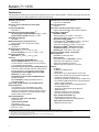
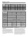
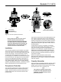
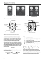
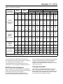
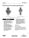
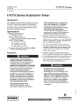
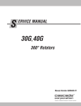
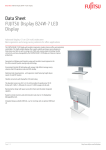
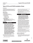
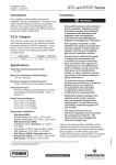
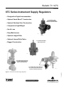
Bulletin 71.1:67C January 2013 67C Series Instrument Supply Regulators • Designed for Digital Instrumentation • Optional Smart Bleed™ Construction 67CF SERIES FILTER REGULATOR SHOWN WITH OPTIONAL PRESSURE GAUGE • Optional Stainless Steel Construction • Compact and Light Weight • No Air Loss • Easy Maintenance W7412 • Optional Integral Filter • Optional Internal Relief Valve 67C SERIES INSTRUMENT SUPPLY REGULATOR • Rugged Construction W8438 67CF SERIES REGULATOR USED AS A SUPPLY REGULATOR FOR DIGITAL INSTRUMENTATION 67CF SERIES REGULATOR USED AS A PILOT SUPPLY REGULATOR FOR THE TYPE 299H PRESSURE REGULATOR W7426 W7423_1 D102656X012 Figure 1. 67C Series Instrument Supply Regulators www.fisherregulators.com Bulletin 71.1:67C Specifications The Specifications section gives some general specifications for the 67C Series regulator. A label on the spring case gives the control spring range for a given regulator as it comes from the factory. Available Constructions See Table 2 Body Size, Inlet, and Outlet Connection Style 1/4 NPT Construction Materials See Table 3 Maximum Inlet Pressure (Body Rating)(1) All except Types 67CS and 67CSR: 250 psig / 17.2 bar Types 67CS and 67CSR: 400 psig / 27.6 bar Outlet Pressure Ranges See Table 1 Maximum Emergency Outlet Pressure(1) 50 psi / 3.4 bar over outlet pressure setting Flow Capacities See Table 4 Wide-Open Flow Coefficients Main Valve: Cg: 11.7; Cv: 0.36; C1: 32.2 Internal Relief Valve: Cg: 1.45; Cv: 0.045; C1: 32.8 IEC Sizing Coefficients Main Valve: XT: 0.66; FL: 0.89; FD: 0.50 Accuracy Inlet Sensitivity for Nitrile (NBR) and Silicone (VMQ) Elastomers: Less than 0.2 psig / 14 mbar change in outlet pressure for every 25 psig / 1.7 bar change in inlet pressure Inlet Sensitivity for Fluorocarbon (FKM) Elastomers: Less than 0.4 psig / 28 mbar change in outlet pressure for every 25 psig / 1.7 bar change in inlet pressure Repeatability for Nitrile (NBR) and Silicone (VMQ) Elastomers: 0.1 psig / 7 mbar(2) Repeatability for Fluorocarbon (FKM) Elastomers: 0.3 psig / 21 mbar(2) Air Consumption: Testing repeatedly shows no discernible leakage Types 67CR, 67CSR, 67CFR, and 67CFSR Internal Relief Performance Low capacity for minor seat leakage only, other overpressure protection must be provided if inlet pressure can exceed the maximum pressure rating of downstream equipment or exceeds maximum outlet pressure rating of the regulator. Approximate Weights Types 67C, 67CR, 67CF, and 67CFR: 1 pound / 0.5 kg Types 67CS and 67CSR: 2.5 pounds / 1.1 kg Types 67CFS and 67CFSR: 4 pounds / 1.8 kg 1. 2. 3. 4. 5. 2 Smart Bleed™ Check Valve Setpoint 6 psi / 0.41 bar differential Pressure Registration Internal Drain Valve and Spring Case Vent Location Aligned with inlet standard, other positions optional Temperature Capabilities(1) With Nitrile (NBR) Standard Bolting: -20 to 180°F / -29 to 82°C Stainless Steel Bolting: -40 to 180°F / -40to 82°C With Fluorocarbon (FKM): Polyethylene Filter(5) (Standard): 0 to 180°F / -18 to 82°C Polyvinylidene (PVDF), Stainless Steel, or Glass Filter (Optional): 0 to 300°F / -18 to 149°C With Silicone (VMQ)(3) Diaphragm and Low Temperature bolting: -60 to 180°F / -51 to 82°C With Gauges: -40 to 180°F / -40 to 82°C Types 67CF, 67CFR, 67CFS, and 67CFSR Filter Capabilities Free Area: 12 times pipe area Micron Rating: Polyethylene Filter(5) (Standard): 5 microns Glass Fiber Filter (Optional): 5 microns PVDF Filter (Optional): 40 microns Stainless Steel Filter (Optional): 40 microns Options All Types • Handwheel adjusting screw • Inlet screen • NACE MR0175(4) or NACE MR0103 construction • Panel mount (includes spring case with 1/4 NPT vent, handwheel, and panel mounting nut) • Closing cap (available on spring case with 1/4 NPT vent) • Fluorocarbon (FKM) elastomers for high temperatures and/or corrosive chemicals • Silicone (VMQ) elastomers for cold temperatures • Fixed Bleed Restriction • Triple scale outlet pressure gauge (Brass or Stainless steel) • Stainless steel stem on the valve plug • Tire valve or pipe plug in second outlet Types 67CFR and 67CFSR only • Smart Bleed internal check valve • Large dripwell with manual or automatic drain Types 67CF and 67CFR only • Stainless steel drain valve The pressure/temperature limits in this Bulletin and any applicable standard or code limitation should not be exceeded. Repeatability is the measure of the regulator’s ability to return to setpoint consistently when traveling from steady state to transient to steady state. Silicone (VMQ) is not compatible with hydrocarbon gas. Product complies with the material requirements of NACE MR0175. Environmental limits may apply. Do not use in high aromatic hydrocarbon service. Bulletin 71.1:67C Table 1. Outlet Pressure Ranges and Control Spring Data TYPE 67C, 67CR, 67CF, and 67CFR 67CS, 67CSR, 67CFS, and 67CFSR CONTROL SPRING DATA OUTLET PRESSURE RANGES Color Material Part Number 0 to 1.4 0 to 2.4 0 to 4.1 0 to 8.6 Green stripe Silver Blue stripe Red stripe Music Wire 0 to 35 0 to 60 0 to 125 0 to 2.4 0 to 4.1 0 to 8.6 Silver stripe Blue Red 0 to 20 0 to 35 0 to 60 0 to 125 0 to 150 0 to 1.3 0 to 2.4 0 to 4.1 0 to 8.6 0 to 10.3 Green Silver stripe Blue Red Black psig bar 0 to 20 0 to 35 0 to 60 0 to 125 Wire Diameter Free Length Inch mm Inch mm GE07809T012 T14059T0012 T14058T0012 T14060T0012 0.135 0.156 0.170 0.207 3.43 3.96 4.32 5.26 1.43 1.43 1.43 1.43 36.2 36.2 36.2 36.2 Inconel® T14113T0012 T14114T0012 T14115T0012 0.156 0.172 0.207 3.96 4.37 5.26 1.43 1.43 1.43 36.2 36.2 36.2 Inconel® 10C1729X012 T14113T0012 T14114T0012 T14115T0012 10C1730X012 0.135 0.156 0.172 0.207 0.250 3.43 3.96 4.37 5.26 6.35 1.50 1.43 1.43 1.43 1.77 38.1 36.2 36.2 36.2 44.9 Inconel® is a marked own by Special Metals Corporation. Introduction for reliable shutoff with no discernible leakage. These regulators are recommended for conserving plant air. The 67C Series regulators are typically used to provide constantly controlled, reduced pressures to pneumatic and electro-pneumatic controllers and other instruments. These direct-operated regulators are suitable for most air or gas applications. Other applications include providing reduced pressures to air chucks, air jets, and spray guns. • Smart Bleed™—Opens to exhaust downstream pressure when inlet pressure drops below outlet pressure. Recommended for dead-end service. Features • Compact—The 67C Series regulators are engineered for outstanding performance in a compact, lightweight package. • Ease of Maintenance—No special tools required to perform maintenance, and all maintenance can be performed with the regulator in the line. Filter elements are easily replaced. The one-piece valve plug cartridge allows easy inspection and replacement. • Panel Mounting—Panel mount construction includes spring case with 1/4 NPT vent, handwheel adjusting screw, and mounting nut. • Rugged Construction—The 67C Series regulators are engineered for longer service life with minimal maintenance requirements. • Instrument Supply Regulator—The Types 67CF, 67CFR, 67CFS, and 67CFSR provide a clean air supply to a variety of pneumatic and electro-pneumatic instrumentation. • Second Outlet—Body side outlet for pressure gauge or other uses. • Digital Instrument Supply Regulator—Designed to meet the accuracy, repeatability, and hysteresis demands of digital instrumentation. • Pilot Supply Regulator—Improves the accuracy of two-path control regulators by reducing inlet sensitivity caused by fluctuating inlet pressures. • Sour Gas Service Capability—NACE MR0175 and MR0103 compliant construction available. • Optional Stainless Steel Construction—The Types 67CS, 67CSR, 67CFS, and 67CFSR provide high resistance to corrosion, which is especially beneficial for offshore applications. • Full Usable Capacity—Fisher® regulators are laboratory tested. 100% of the published capacities can be used with confidence. • Internal Relief—The Types 67CR, 67CSR, 67CFR, and 67CFSR have an internal relief valve with a soft seat • Integral Filter—The Types 67CF, 67CFR, 67CFS, and 67CFSR have an integral filter ensuring clean downstream air supply. • Powder Paint Coating—Types 67C, 67CR, 67CF, and 67CFR are powder paint coated, offering impact, abrasion, and corrosion resistance. Stainless steel regulators (Types 67CS, 67CSR, 67CFS, and 67CFSR) are not painted. • Corrosion Resistant Fasteners—Bolting and adjusting screw are double zinc-chromated for enhanced corrosion resistance. Optional stainless steel bolting and adjusting screw are also available. Principle of Operation (Figure 2) Downstream pressure is registered internally on the lower side of the diaphragm. When the downstream pressure is at or above the set pressure, the valve plug is held against the orifice and there is no flow through the regulator. When demand increases, downstream pressure drops slightly allowing the spring to extend, moving the stem down and the valve plug away from the orifice. This allows flow through the regulator. 3 Bulletin 71.1:67C Table 2. Available Constructions CONSTRUCTION FEATURES TYPE With Internal Relief OPTIONAL FEATURES Smart Bleed™ Internal Check Valve Airset With Filter BODY MATERIAL Drain Valve Fixed Bleed Aluminum X X 67C 67CR Stainless Steel X X 67CS 67CSR X X X 67CF 67CFR X X X 67CFS 67CFSR X X X X X X X X X X X X X X X X Table 3. Construction Materials MATERIALS BODY AND SPRING CASE BOTTOM PLATE TYPE 67C and 67CR 67CF and 67CFR 67CS and 67CSR Aluminum (ASTM B85/Alloy 380) 316 Stainless steel 67CFS and 67CFSR CF8M/CF3M Stainless steel ---- 316 Stainless steel PUSHER POST AND VALVE CARTRIDGE ---- Polyester resin UPPER SPRING SEAT Zinc-plated steel 316 Stainless steel LOWER SPRING SEAT, DIAPHRAGM PLATE Chromate conversion coated Aluminum 316 Stainless steel CONTROL SPRING Plated Steel or Inconel® (NACE) Inconel® VALVE PLUG Brass stem with Nitrile (NBR) plug, Aluminum stem with Nitrile (NBR) or Fluorocarbon (FKM) plug, or Stainless steel stem with Nitrile (NBR) plug 316 Stainless steel stem with Nitrile (NBR) or Fluorocarbon (FKM) plug VALVE SPRING Stainless steel or Inconel® (NACE) Inconel® DIAPHRAGM AND O-RINGS Nitrile (NBR), Fluorocarbon (FKM), or Silicone (VMQ)(1) SOFT SEAT AND GASKETS Nitrile (NBR) or Fluorocarbon (FKM) BOLTING, ADJUSTING SCREW, LOCKNUT Zinc-plated steel or Stainless steel HANDWHEEL FILTER RETAINER Stainless steel Zinc-plated steel screw with resin handwheel ---- Plated Steel ---- 316 Stainless steel FILTER ELEMENT ---- Polyethylene, Glass fiber, Stainless steel, or PVDF (Plastic) ---- Polyethylene, Glass fiber, 316 Stainless steel, or PVDF (Plastic) DRAIN VALVE ---- Brass or Stainless steel ---- 316 Stainless steel or 18-8 Stainless steel DRIPWELL ---- Aluminum (ASTM B85/Alloy 380) ---- CF8M/CF3M Stainless steel 1. Silicone (VMQ) diaphragm is only available with internal relief (Types 67CR, 67CSR, 67CFR, and 67CFSR). Inconel® is a marked own by Special Metals Corporation. Internal Relief (Types 67CR, 67CSR, 67CFR, and 67CFSR) If for some reason, outside of normal operating conditions, the downstream pressure exceeds the setpoint of the regulator, the force created by the downstream pressure will lift the diaphragm until the diaphragm is lifted off the relief seat. This allows flow through the token relief. The relief valve on the Type 67CR, 67CSR, 67CFR, or 67CFSR is an elastomer plug that prevents leakage of air from the downstream to atmosphere during normal operation, thereby conserving plant air. 4 Smart Bleed Airset In some cases, it is desired to exhaust downstream pressure if inlet pressure is lost or drops below the setpoint of the regulator. For example, if the regulator is installed on equipment that at times has no flow demand but is expected to backflow on loss of inlet pressure. The Type 67CFR or 67CFSR can be ordered with the Smart Bleed option which includes an internal check valve for this application. During operation, if inlet pressure is lost, or decreases below the setpoint of the regulator, the downstream pressure will back flow upstream through the regulator and check valve. This option eliminates the need for a fixed bleed downstream of the regulator, thereby conserving plant air. Month Year Bulletin 71.1:67C Type XXXX TYPE 67CF OR 67CFS TYPE 67CR OR 67CSR TYPE 67C OR 67CS W8442 INLET PRESSURE OUTLET PRESSURE ATMOSPHERIC PRESSURE SMART BLEED™ OPTION TYPE 67CFR OR 67CFSR ONLY W7433 TYPE 67CFR OR 67CFSR Figure 2. 67C Series Operational Schematics INLET PRESSURE OUTLET PRESSURE ATMOSPHERIC PRESSURE NoteLOADING PRESSURE PRESSURE operation INTERMEDIATE the check valve’s PILOT SUPPLY PRESSURE During normal metal to metal seat allows limited flow through the regulator from the inlet to outlet, even when there is no downstream demand. To prevent downstream pressure buildup, the smart bleed option is only available with the internal relief version of the 67C Series. Installation The 67C Series regulators may be installed in any position. Spring case vents must be protected against the entrance of rain, snow, debris, or any other foreign material that might plug the vent openings. The inlet connection is marked “In” and the two outlet connections are marked “Out”. If a pressure gauge is not installed in one outlet connection, plug the unused connection. See Figures 5 to 9 for dimensions. Emerson Process Management Regulator Technologies, Inc. (Regulator Technologies) provides an instruction manual with every regulator shipped. Refer to this for complete installation, operation, and maintenance instructions. Included is a complete listing of individual parts and recommended spare parts. Overpressure Protection The 67C Series regulators have maximum outlet pressure ratings that are lower than their maximum inlet pressure ratings. A pressure-relieving or pressure-limiting device is needed if inlet pressure can exceed the maximum outlet pressure rating. Types 67CR, 67CSR, 67CFR, and 67CFSR regulators have a low capacity internal relief valve for minor seat leakage only. Other overpressure protection must be provided if the maximum inlet pressure can exceed the maximum pressure rating of the downstream equipment or exceeds maximum outlet pressure rating of the Type 67CR, 67CSR, 67CFR, or 67CFSR regulator. Overpressuring any portion of a regulator or associated equipment may cause leakage, parts damage, or personal injury due to bursting of pressure-containing parts or explosion of accumulated gas. Regulator operation within ratings does not preclude the possibility of damage from external sources or from debris in the pipeline. A regulator should be inspected for damage periodically and after any overpressure condition. Refer to the Capacity Information section and the Wide-Open Flow Coefficients for Relief Valve Sizing in the Specifications section on page 2 to determine the required relief valve capacity. Capacity Information Table 4 shows the air regulating capacities of the 67C Series regulators at selected inlet pressures and outlet pressure settings. Flows are shown in SCFH (at 60°F and 14.7 psia) and in Nm3/h (at 0°C and 1.01325 bar) of air. Note The 67C Series regulators may be sized for 100% flow using capacities as shown in Table 4. It is not necessary to reduce published capacities. 5 Bulletin 71.1:67C W3123 W3122_1 1-GAUGE PANEL W0554 2-GAUGE PANEL 2-GAUGE PANEL WITH CHANGEOVER VALVE Figure 3. 670 Series Typical Panel Layouts GAUGE DRAIN VALVE POSITION 4 VENT POSITION 2 FLANGE SCREW DRAIN VALVE POSITION 1 (STANDARD) OUTLET INLET 250 PSI MAX INLET VENT POSITION 3 VENT POSITION 1 (STANDARD) INLET DRAIN VALVE POSITION 3 OUTLET FLANGE SCREW GAUGE VENT POSITION 4 B2699_C DRAIN VALVE POSITION 2 T40573_2B VENT POSITION DRAIN VALVE POSITIONS Figure 4. 67C Series Vent and Drain Valve Positions To determine the equivalent capacities for other gases, multiply the table capacity by the following appropriate conversionfactor:1.29for0.6specificgravitynaturalgas, 0.810 for propane, 0.707 for butane, or 1.018 for nitrogen. Forgasesofotherspecificgravities,dividethetable capacitiesbythesquarerootoftheappropriatespecific gravity.Tofindwide-openflowcapacitiesforreliefsizingat any inlet pressure, perform one of the following procedures. Then, if necessary, convert using the factors provided above. For critical pressure drops (absolute outlet pressure equal to or less than one-half of absolute inlet pressure), use the following formula: Q = (P1)(Cg) For pressure drops lower than critical (absolute outlet pressure greater than one-half of absolute inlet pressure), use the following formula: Q = 6 520 CgP1SIN GT ) 3417 C1 P P1 ) DEG where, Q P1 Cg G T C1 P =gasflowrate,SCFH = absolute inlet pressure, psia (P1 gauge + 14.7) =gassizingcoefficient =specificgravityofthegas = absolute temperature of gas at inlet, °Rankine =flowcoefficient(Cg ÷ Cv) = pressure drop across the regulator, psi Then, if capacity is desired in normal cubic meters per hour (at 0°C and 1.01325 bar), multiply SCFH by 0.0268. 670 Series Panel-Mounted Loading Regulators (Figure 3) The 670 Series panel-mounted loading regulators are compact, rugged units used primarily for manually loading pressure-balanced gas regulators and providing manual control for diaphragm actuator control valves. Applications include remote control of gas pressure to burners in refineries,powerplants,andvariousprocessfurnaces. Bulletin 71.1:67C Table 4. 67C Series Flow Capacities OUTLET PRESSURE RANGE, SPRING PART NUMBER AND COLOR CODE OUTLET PRESSURE psig 0 to 125 psig / 0 to 8.6 bar T14060T0012 (Red stripe) T14115T0012 (Red) 0 to 150 psig / 0 to 10.3 bar(2) 10C1730X012 (Black) 10% Droop 20% Droop Types 67CF, 67CFR, 67CFS, and 67CFSR 10% Droop 20% Droop psig bar SCFH Nm3/h SCFH Nm3/h SCFH Nm3/h SCFH Nm3/h 1.0 50 75 100 150 250 400 3.4 5.2 6.9 10.3 17.2 27.6(1) 250 340 430 680 1300 390 6.7 9.1 11.5 18.2 34.8 10.5 430 610 800 1200 1900 1850 11.5 16.3 21.4 32.2 50.9 50.0 250 300 330 400 450 ---- 6.7 8.0 8.8 10.7 12.1 ---- 430 690 1000 1600 1800 ---- 11.5 18.5 26.8 42.9 48.2 ---- 1.4 50 75 100 150 250 400 3.4 5.2 6.9 10.3 17.2 27.6(1) 310 420 620 960 1550 1200 8.3 11.3 16.6 25.7 41.5 32.2 460 700 940 1450 2150 2750 12.3 18.8 25.2 38.9 57.6 73.7 350 530 750 1400 2550 ---- 9.4 14.2 20.1 37.5 68.3 ---- 500 820 1100 1600 2700 ---- 13.4 22.0 29.5 42.9 72.4 ---- 2.4 50 75 100 150 250 400 3.4 5.2 6.9 10.3 17.2 27.6(1) 390 590 770 1200 2200 2850 10.5 15.8 20.6 32.2 58.9 76.4 490 850 1150 1750 2700 3450 13.1 22.8 30.8 46.9 72.4 92.5 390 640 840 1450 2450 ---- 10.4 17.2 22.5 38.9 65.7 ---- 500 820 1100 1650 2700 ---- 13.4 22.0 29.5 42.9 72.4 ---- 2.4 50 75 100 150 250 400 3.4 5.2 6.9 10.3 17.2 27.6(1) 310 440 560 780 1450 770 8.3 11.8 15.0 20.9 38.9 20.6 440 670 900 1350 2200 2500 11.8 18.0 24.1 36.2 59.0 67.0 330 500 700 1050 2000 ---- 8.8 13.4 18.8 28.1 53.6 ---- 470 730 1000 1550 2600 ---- 12.6 19.6 26.8 41.5 69.7 ---- 60 4.1 75 100 150 250 400 5.2 6.9 10.3 17.2 27.6(1) 520 750 1100 2050 3200 13.9 20.1 29.5 54.9 85.8 720 1050 1700 2850 4300 19.3 28.1 45.6 76.4 115 520 770 1100 2450 ---- 13.9 20.6 29.5 65.7 ---- 720 1000 1600 2750 ---- 19.3 26.8 42.9 73.7 ---- 80 5.5 100 150 250 400 6.9 10.3 17.2 27.6(1) 500 750 1200 910 13.4 20.1 32.2 24.4 800 1200 2050 3700 21.4 32.2 54.9 99.2 530 780 1250 ---- 14.2 20.9 33.5 ---- 780 1200 2200 ---- 20.9 32.2 59.0 ---- 125 8.6 150 250 400 10.3 17.2 27.6(1) 900 1560 2200 24.1 41.8 59.0 1250 2450 4350 33.5 65.7 117 900 1650 ---- 24.1 44.2 ---- 1150 2450 ---- 30.8 65.7 ---- 80 5.5 250 400 17.2 27.6(1) 550 400 14.7 10.7 1200 1100 32.2 29.5 550 ---- 14.7 ---- 1200 ---- 32.2 ---- 135 9.3 250 400 17.2 27.6(1) 970 840 26.0 22.5 1800 2350 48.2 63.0 1100 ---- 29.5 ---- 1800 ---- 48.2 ---- 150 10.3 250 400 17.2 27.6(1) 1100 940 29.5 25.2 1850 2500 49.6 67.0 1100 ---- 29.5 ---- 1850 ---- 49.6 ---- 20 35 0 to 60 psig / 0 to 4.1 bar T14058T0012 (Blue stripe) T14114T0012 (Blue) CAPACITIES IN SCFH / Nm3/h OF AIR Types 67C, 67CR, 67CS, and 67CSR bar 15 0 to 35 psig / 0 to 2.4 bar T14059T0012 (Silver) T14113T0012 (Silver stripe) INLET PRESSURE 35 1. Inlet pressures above 250 psig / 17.2 bar with a maximum of 400 psig / 27.6 bar are only available on Types 67CS and 67CSR. 2. Available for Types 67CS, 67CSR, 67CFS, and 67CFSR only. Three basic panels are available within the product line, each having one 67C Series pressure regulator connected to one or two gauges and a changeover valve. A single gauge typically shows loading pressure to the control valve. For more information, see Bulletin 62.3:670. service comply with the chemical, physical, and metallurgical requirements of NACE MR0175 and/or NACE MR0103. Customers have the responsibility to specify correct materials. Environmental limitations may apply and shall be determined by the user. NACE Universal Compliance Ordering Information Optional materials are available for applications handling sour gases. These constructions comply with the recommendations of NACE International sour service standards. The manufacturing processes and materials used by Emerson assure that all products specified for sour gas When ordering, complete the Ordering Guide on pages 11 and 12. Refer to the Specifications section on page 2. Review the description to the right of each specification and the information in each referenced table or figure. Specify your choice whenever a selection is offered. 7 Bulletin 71.1:67C 2.56 / 65 4.56 / 116 0.50 / 13 2.92 / 74 1.46 / 37 A MAXIMUM OPTIONAL GAUGE OUTLET CONNECTIONS 1/4 NPT INLET CONNECTION 1/4 NPT B SIDE OUTLET 1/4 NPT STANDARD DIMENSIONS FOR GAUGE OPTION STANDARD DIMENSIONS 2.56 / 65 4.56 / 116 1.43 / 36 2.92 / 74 CLOSING CAP 1.46 / 37 0.72 / 18 SPRING CASE PANEL BOSS 2.37 / 60 MAXIMUM PANEL 0.12 TO 0.25 / 3.0 TO 6.4 A A MAXIMUM 1/4 NPT VENT D C OUTLET CONNECTIONS 1/4 NPT OPTIONAL GAUGE INLET CONNECTION 1/4 NPT SIDE OUTLET TAPPED 1/4 NPT DIMENSIONS FOR PANEL MOUNT OPTION WITH HANDWHEEL AND 1/4 NPT SPRING CASE VENT INCHES / mm DIMENSIONS WITH CLOSING CAP AND 1/4 NPT SPRING CASE VENT Figure 5. Types 67C, 67CR, 67CS, and 67CSR Dimensions Table 5. Types 67C, 67CR, 67CS, and 67CSR Dimensions STANDARD DIMENSIONS TYPE 67C and 67CR 67CS and 67CSR 8 A Inches 3.50 4.13 B mm 89 105 Inches 1.51 1.62 mm 38 41 DIMENSION WITH CLOSING CAP A Inches mm 4.60 117 4.93 125 PANEL MOUNT OPTION WITH HANDWHEEL DIMENSIONS A Inches 4.69 5.00 C mm 119 127 Inches 1.08 1.14 D mm 27 29 Inches 2.33 2.65 mm 59 67 Bulletin 71.1:67C 4.56 / 116 3.00 / 76 2.56 / 65 0.62 / 16 1.48 / 38 3.50 / 89 OUTLET CONNECTIONS 1/4 NPT INLET CONNECTION 1/4 NPT 0.69 / 18 IN IN OPTIONAL GAUGE MOUNTING HOLES FOR 5/16 / 7.9 DIAMETER BOLTS 3.50 / 89 SIDE OUTLET 1/4 NPT B2699-B DIMENSIONS FOR GAUGE OPTION B2699-A 3.00 / 76 2.37 / 60 MAXIMUM PANEL 0.12 TO 0.25 / 3.0 TO 6.4 2.25 / 57 2.87 / 73 STANDARD DIMENSIONS 4.56 / 116 1.43 / 36 2.56 / 65 CLOSING CAP 1.48 / 38 0.72 / 18 SPRING CASE PANEL BOSS 4.78 / 121 MAXIMUM 4.69 / 119 1/4 NPT VENT 2.41 / 61 MAXIMUM INLET CONNECTION 1/4 NPT 1.14 / 29 OUTLET CONNECTIONS 1/4 NPT 0.69 / 18 IN OPTIONAL GAUGE MOUNTING HOLES FOR 5/16 / 7.9 DIAMETER BOLTS 3.50 / 89 SIDE OUTLET TAPPED 1/4 NPT B2700-A B2700-B DIMENSIONS FOR PANEL MOUNT OPTION WITH HANDWHEEL AND 1/4 NPT SPRING CASE VENT Figure 6. Types 67CF and 67CFR Dimensions 2.25 / 57 2.87 / 73 INCHES / mm DIMENSIONS FOR CLOSING CAP OPTION WITH 1/4 NPT SPRING CASE VENT 9 Bulletin 71.1:67C 1.46 / 37 2.92 / 74 4.56 / 116 1.29 / 33 2.58 / 66 2.79 / 71 OPTIONAL GAUGE 0.23 / 5.8 4.70 / 119 VENT 6.34 / 161 2.33 / 59 SIDE OUTLET 1/4 NPT 1.64 / 42 INLET 1/4 NPT FOR TYPES 67C, 67CR, 67CF, AND 67CFR ONLY Figure 7. Dimensions for 3-Hole Panel Mount Option With Handwheel and 1/4 NPT Spring Case Vent 0.18 / 4.6 SPACER (FOR INSTALLING A 67CF SERIES REGULATOR IN AN EXISTING INSTALLATION IF THE MOUNTING BOLTS ARE TOO LONG) 0.50 / OD 13 0.32 / 8.1 ID IN B2697_B SPACER OUTER DIAMETER SPACER WIDTH AND INNER DIAMETER INCHES / mm B2697_A Figure 8. Spacer Dimensions and Installation Schematic 3.00 / 76 1.43 / 36 2.56 / 65 0.62 / 16 4.56 / 116 1.48 / 38 CLOSING CAP VENT 1/4 NPT 4.93 / 125 1/4 NPT INLET CONNECTION 1.14 / 29 4.00 / 102 0.69 / 18 MOUNTING HOLES FOR 5/16 / 7.9 DIAMETER BOLTS OPTIONAL GAUGE 1/4 NPT INLET CONNECTION GE03199 STANDARD DIMENSIONS (INCLUDING CLOSING CAP) Figure 9. Types 67CFS and 67CFSR Dimensions 10 1/4 NPT OUTLET CONNECTIONS 2.25 / 57 2.87 / 73 INCHES / mm STANDARD DIMENSIONS (INCLUDING CLOSING CAP) Bulletin 71.1:67C 2.37 / 60 MAXIMUM 4.13 / 105 MAXIMUM 5.00 / 127 MAXIMUM PANEL 0.12 TO 0.25 / 3.0 TO 6.4 2.65 / 67 INCHES / mm GE03268 DIMENSIONS WITHOUT CLOSING CAP DIMENSIONS FOR PANEL MOUNT OPTION WITH HANDWHEEL Figure 9. Types 67CFS and 67CFSR Dimensions (continued) Ordering Guide Type (Select One) 67C (Aluminum without internal relief)*** 67CR (Aluminum with internal relief)*** 67CS (Stainless steel without internal relief)*** 67CSR (Stainless steel with internal relief)*** 67CF (Aluminum with filter and without internal relief)*** 67CFR (Aluminum with filter and internal relief)*** 67CFS (Stainless steel with filter and without internal relief)*** 67CFSR (Stainless steel with filter and internal relief)*** Quantity (Specify) ____________ Spring Case Style (Select One) Drilled hole vent (Types 67C, 67CR, 67CF, and 67CFR standard)*** 1/4 NPT vent (Types 67CS, 67CSR, 67CFS, and 67CFSR standard)*** Single hole panel mount*** 3-hole panel mount (Types 67C, 67CR, 67CF, and 67CFR only)*** Adjusting Screw (Select One) Square head (Types 67C, 67CR, 67CF, and 67CFR standard)*** Square head with closing cap (Types 67CS, 67CSR, 67CFS, and 67CFSR standard)*** Handwheel*** Outlet Pressure Range (Select One) 0 to 20 psig / 0 to 1.4 bar*** 0 to 35 psig / 0 to 2.4 bar*** 0 to 60 psig / 0 to 4.1 bar*** 0 to 125 psig / 0 to 8.6 bar*** 0 to 150 psig / 0 to 10.3 bar (Types 67CS, 67CSR, 67CFS, and 67CFSR only)*** Diaphragm, O-Rings, and Valve Plug (Select One) Nitrile (NBR) (standard)*** Fluorocarbon (FKM)** Silicone (VMQ) diaphragm, O-rings, and Nitrile (NBR) valve plug* Filter Material (Select One) Polyethylene (5 microns) (standard)*** Glass (5 microns)*** PVDF (Plastic) (40 microns)*** Stainless steel (40 microns)*** Dripwell Standard Large capacity with manual drain valve Large capacity with automatic drain valve, Nitrile (NBR) Large capacity with automatic drain valve, Fluorocarbon (FKM) Drain Valve (for Manual Drain Only) (Select One) Brass (Types 67CF and 67CFR standard)*** Stainless steel (Types 67CFS and 67CFSR standard)*** Drain Valve Location (for Standard Dripwell Only) (Select One) Position 1 - Aligned with inlet (standard)*** Position 2 Position 3 Position 4 Spring Case Vent Location (Select One) Position 1 - Aligned with inlet (standard)*** Position 2 Position 3 Position 4 Fixed Bleed for Type 67CR, 67CSR, 67CFR, or 67CFSR (Optional) Yes** 11 Bulletin 71.1:67C Ordering Guide (continued) Smart Bleed™ Internal Check Valve Airset for Types 67CFR and 67CFSR (Optional) Yes** Second Outlet (Select One) Open (Types 67C, 67CR, 67CF, and 67CFR standard)*** P lugged with pipe plug (Types 67CS, 67CSR, 67CFS, and 67CFSR standard)*** Tire Valve*** Pressure Gauge (see below) NACE MR0103 Construction (Optional) Yes (not available with gauge)** Replacement Parts Kit (Optional) Yes, send one replacement parts kit to match this order. Triple Scale Pressure Gauge (Optional) B rass Gauge or Stainless Steel Gauge 0 to 30 psig / 0 to 0.2 MPa / 0 to 2.1 bar*** 0 to 60 psig / 0 to 0.4 MPa / 0 to 4.1 bar*** 0 to 160 psig / 0 to 1.1 MPa / 0 to 11.0 bar*** NACE MR0175 Construction (Optional)(1) Yes (not available with gauge)** 1. Product complies with the material requirements of NACE MR0175. Environmental limits may apply. Regulators Quick Order Guide *** ** * Readily Available for Shipment Allow Additional Time for Shipment Special Order, Constructed from Non-Stocked Parts. Consult your local Sales Office for Availability. Availability of the product being ordered is determined by the component with the longest shipping time for the requested construction. Specification Worksheet Application (Please designate units): Specific Use Line Size Gas Type and Specific Gravity Gas Temperature Does the Application Require Overpressure Protection? Yes No If yes, which is preferred: Relief Valve Monitor Regulator Shutoff Device Is overpressure protection equipment selection assistance desired? Pressure (Please designate units): Maximum Inlet Pressure (P1max) Minimum Inlet Pressure (P1min) Downstream Pressure Setting(s) (P2) Maximum Flow (Qmax) Performance Required: Accuracy Requirements? Need for Extremely Fast Response? Other Requirements: Industrial Regulators Natural Gas Technologies TESCOM Emerson Process Management Regulator Technologies, Inc. Emerson Process Management Regulator Technologies, Inc. Emerson Process Management Tescom Corporation USA - Headquarters McKinney, Texas 75069-1872, USA Tel: +1 800 558 5853 Outside U.S. +1 972 548 3574 USA - Headquarters McKinney, Texas 75069-1872, USA Tel: +1 800 558 5853 Outside U.S. +1 972 548 3574 USA - Headquarters Elk River, Minnesota 55330-2445, USA Tels: +1 763 241 3238 +1 800 447 1250 Asia-Pacific Shanghai 201206, China Tel: +86 21 2892 9000 Asia-Pacific Singapore 128461, Singapore Tel: +65 6770 8337 Europe Selmsdorf 23923, Germany Tel: +49 38823 31 287 Europe Bologna 40013, Italy Tel: +39 051 419 0611 Europe Bologna 40013, Italy Tel: +39 051 419 0611 Chartres 28008, France Tel: +33 2 37 33 47 00 Asia-Pacific Shanghai 201206, China Tel: +86 21 2892 9499 Middle East and Africa Dubai, United Arab Emirates Tel: +971 4811 8100 For further information visit www.fisherregulators.com The Emerson logo is a trademark and service mark of Emerson Electric Co. All other marks are the property of their prospective owners. Fisher is a mark owned by Fisher Controls International LLC, a business of Emerson Process Management. The contents of this publication are presented for informational purposes only, and while every effort has been made to ensure their accuracy, they are not to be construed as warranties or guarantees, express or implied, regarding the products or services described herein or their use or applicability. We reserve the right to modify or improve the designs or specifications of such products at any time without notice. Emerson Process Management Regulator Technologies, Inc. does not assume responsibility for the selection, use or maintenance of any product. Responsibility for proper selection, use and maintenance of any Emerson Process Management Regulator Technologies, Inc. product remains solely with the purchaser. ©Emerson Process Management Regulator Technologies, Inc., 2001, 2013; All Rights Reserved