1
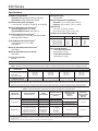
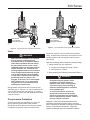
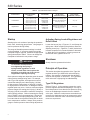
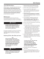
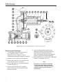
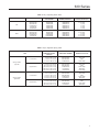
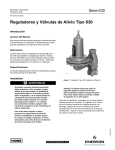
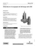
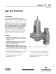
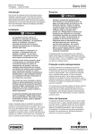
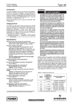
630 Series
Instruction Manual
Form 1243
November 2008
630 Series Regulators and Relief Valves
Introduction
Scope of Manual
This Instruction Manual provides operating,
installation, maintenance, and parts information for the
630 Series regulators and relief valves.
Description
The 630 Series consists of self-operated, spring
loaded Type 630 Big Joe® pressure regulators and
Type 630R relief valves, which are designed for
maximum inlet pressures to 1500 psig (103 bar) and
outlet pressures from 3 to 500 psig (0,21 to 34,5 bar).
Specifications
Specifications section lists the specifications for the
630 Series constructions.
Installation
W1934
!
Figure 1. Spring-Loaded Type 630 Regulator
Warning
Personal injury, property damage,
equipment damage, or leakage due to
escaping gas or bursting of pressurecontaining parts may result if this
regulator is overpressured or is installed
where service conditions could exceed
the limits given in Specifications section,
Tables 1 through 3 or where conditions
exceed any ratings of the adjacent piping
or piping connections.
Additionally, physical damage to the
regulator could cause personal injury or
property damage due to escaping gas.
To avoid such injury or damage, install
the regulator in a safe location.
Before installing, inspect the unit for any damage and
any foreign material. The regulator or relief valve may
be mounted in any position, however, ensure that the
flow direction corresponds with the direction of the
arrow on the nameplate. Apply a good grade of pipe
compound to the male threads of the pipeline.
D100300X012
To avoid such injury or damage,
provide pressure-relieving or pressure-limiting devices (as required
by the appropriate code, regulation, or
standard) to prevent service conditions
from exceeding those limits.
www.emersonprocess.com/regulators
630 Series
Specifications
Spring Case Vent
1/4-inch NPT
Available Configurations
Type 630: Spring-loaded reducing regulators
Type 630R: Spring-loaded relief valves
End Connection Sizes and Styles
1 or 2-inch NPT, CL150 RF, CL300 RF, or CL600 RF
Material Temperature Capabilities(1)
Standard: -20° to 180°F (-29° to 82°C)
Optional: -20° to 300°F (-29° to 149°C)
Maximum Allowable Inlet Pressures(1)
Type 630 Regulators: See Table 1
Type 630R Relief Valves: See Table 3
Orifice Sizes
1/8, 3/16, 1/4, 3/8,or 1/2-inch
(3,18; 4,76; 6,35; 9,53; or 12,7 mm)
Type 630 Outlet Pressure Ranges(1)
3 to 500 psig (0,21 to 34,5 bar) with intermediate
values shown in Table 2
Coefficients for Relief Valve Sizing
orifice size
1/8-inch
3/16-inch
1/4-inch
3/8-inch
1/2-inch
Type 630R Relief Pressure Ranges(1)
3 to 250 psig (0,21 to 17,2 bar)
See Table 3
Maximum Allowable Outlet Pressures(1)
See Table 2
(3,18 mm)
(4,76 mm)
(6,35 mm)
(9,53 mm)
(12,7 mm)
Cg
Cv
C1
13.9
31.3
55.1
122.5
216.0
0.49
1.11
2.03
4.61
8.18
28.4
28.2
27.2
26.6
26.4
Approximate Weights
1-inch End Connection:
25 pounds (11,3 kg)
2-inch End Connection:
30 pounds (13,6 kg)
Maximum Allowable Pressure Drops(1)
See Table 1
Pressure Registration
Internal
1. The pressure/temperature limits in this Instruction Manual or any applicable standard limitation should not be exceeded.
Table 1. Maximum Allowable Inlet Pressures and Pressure Drops. Maximum inlet pressure not to exceed 1500 psig (103 bar).
DISK MATERIAL
Orifice Size, inchES (mm)
1/4 (6,35)
3/8 (9,52)
1/8 and 3/16 (3,17 and 4,76)
Nylon (PA) and
Polytetrafluoroethylene (PTFE)
Nitrile (NBR)
Fluorocarbon (FKM)
Maximum Allowable Inlet
Pressure, Psig (bar)
1500 (103)
600 (41,4)
200 (13,8)
1000 (68,9)
600 (41,4)
200 (13,8)
500 (34,5)
500 (34,5)
200 (13,8)
1500 (103)(1)
1500 (103)(1)
1000 (68,9)(1)
1/2 (12,7)
250 (17,2)
250 (17,2)
200 (13,8)
750 (51,7)(1)
1. Inlet pressure must not exceed the sum of the actual outlet pressure setting and the maximum allowable pressure drop. For example, with an outlet pressure setting of 200 psig
(13,8 bar) and a 3/8-inch (9,53 mm) orifice with a maximum allowable pressure drop of 500 psid (34,5 bar, differential), the maximum allowable inlet pressure is 700 psig (48,3 bar).
2. Nitrile (NBR) valve disks are normally furnished for pressure drops to 200 psi (13,8 bar, differential). For better erosion resistance, nylon valve disks are normally furnished for higher
pressure drops. Some erosion of valve disks occurs at all pressure drops due to solid particles in the flow stream. The rate of erosion is higher with large amounts of impurities in
the flow stream and with high pressure drops. Valve disks and other regulator parts must be inspected periodically for erosion and damage and must be replaced as necessary.
Table 2. Type 630 Regulator Outlet Pressure Ranges and Maximum Outlet Pressures
Regulator
construction
Low-Pressure
High-Pressure
Outlet Pressure
Range, Psig (bar)
SPRING
Part Number
MAXIMUM OPERATING
OUTLET PRESSURE,
PSIG (bar)
3 to 10 (0,21 to 0,69)
8 to 20 (0,55 to 1,38)
17 to 30 (1,17 to 2,07)
0W019227022
0W019127022
0W019027022
10 (0,69)
20 (1,38)
30 (2,07)
27 to 40 (1,86 to 2,76)
0Y066427022
40 (2,76)
27 to 50
46 to 95
90 to 150
150 to 200
200 to 275
275 to 500
(1,86 to 3,45)
(3,17 to 6,55)
(6,21 to 10,3)
(10,3 to 13,8)
(13,8 to 19,0)
(19,0 to 34,5)
0W019227022
0W019127022
0W019027022
0Y066427022
1J146927142
1K370927082
50
95
150
200
275
500
(3,45)
(6,55)
(10,3)
(13,8)
(19,0)
(34,5)
Maximum Outlet
Pressure Over
SETPOINT(1),
Psig (bar)
Maximum
Emergency
Outlet (Casing)
Pressure(4),
psig (bar)
20 (1,38)
20(2) (1,38)
Limited by Maximum
Emergency Outlet Pressure
200 (13,8)
66 (4,55)
550 (37,9)
200(3) (13,8)
1. Damage to internal parts of the regulator may occur if outlet pressure exceeds the actual pressure setting by amounts greater than those shown in this column.
2. For outlet pressure settings to 25 psig (1,72 bar) only. For pressure settings over 25 psig (1,72 bar), outlet pressure is limited by maximum emergency outlet pressure of 45 psig (3,10 bar).
3. For outlet pressure settings to 350 psig (24,1 bar) only. For pressure settings over 350 psig (24,1 bar), outlet pressure is limited by maximum emergency outlet pressure of
550 psig (37,9 bar).
4. Leakage or bursting of pressure-containing parts may occur if outlet pressure exceeds these values.
2
630 Series
inlet pressure
outlet pressure
Atmospheric pressure
inlet pressure
outlet pressure
Atmospheric pressure
46A2977
A2526-1
46A2976-A
A2525-1
Figure 3. Type 630R Relief Valve Operational Schematic
Figure 2. Type 630 Regulator Operational Schematic
Vents
!
Warning
When the unit is installed in an enclosed
area or indoors, escaping gas may
accumulate and be an explosion hazard.
Under these conditions the vent should
be piped away from the unit to a freely
ventilated outdoor location away from air
intakes, windows, etc. Protect all vent
openings against weather or the entrance
of any foreign material that may plug the
vent or affect operation of the regulator
or relief valve. Inspect all vent openings
periodically to be sure they are not
plugged. If the vent is in an environment
where freezing rain, ice, or snow could
clog the vent, it is recommended that a
weatherproof vent be used.
Spring-loaded constructions have a screened vent
assembly (key 27, Figures 4, 5, and 6) installed in the
1/4-inch NPT spring case vent opening. If a remote
vent is required, remove the vent assembly and install
a remote vent line.
Overpressure Protection
As is the case with most regulators, the Type 630
spring-loaded regulators have outlet pressure
ratings that are lower than the inlet pressure ratings.
Overpressure protection must be provided if the
actual inlet pressure can exceed the outlet pressure
rating. Overpressure protection is also required for the
loading regulator and main regulator spring case of
relief valves.
Refer to the following tables to determine pressure ratings:
1. Spring-loaded Type 630 regulators.
a. Inlet pressure and pressure drop—Table 1.
b. Outlet pressure—Table 2.
2. Spring-loaded Type 630R relief valve pressure Table 3.
!
Warning
Overpressuring any portion of this
equipment may cause damage to
regulator parts, leaks in the regulator,
or personal injury due to bursting of
pressure-containing parts or explosion
of accumulated gas.
To avoid overpressure, provide an
appropriate overpressure protection
device to ensure that none of the limits
listed in Specifications section, Tables 1
through 3 will be exceeded.
Regulator or relief valve operation below the limits
specified in Specifications section, Tables 1 through 3
does not preclude the possibility of damage from external
sources or from debris in the gas line. Inspect the
regulator for damage after any overpressure condition.
3
630 Series
Table 3. Type 630R Relief Pressure Ranges
Relief (inlet)
Pressure Ranges,
Psig (bar)
Relief Valve
construction
Part Number
Maximum Allowable
Relief (Inlet)
Pressure, psig (bar)
Maximum Emergency
INlet (casing)
Pressure(1), Psig (bar)
Low-Pressure
3 to 8
6 to 17
15 to 22
20 to 35
35 to 50
(0,21 to 0,55)
(0,41 to 1,17)
(1,03 to 1,52)
(1,38 to 2,41)
(2,41 to 3,45)
0W019227022
0W019127022
0W019027022
0Y066427022
1J146927142
Relief Pressure Setting Plus
Maximum Allowable Buildup
of 25 psig (1,72 bar)
75 (5,17)
High-Pressure
30 to 70
50 to 95
75 to 175
150 to 250
(2,07 to 4,83)
(3,45 to 6,55)
(5,17 to 12,1)
(10,3 to 17,2)
0W019127022
0W019027022
0Y066427022
1J146927142
Relief Pressure Setting Plus
Maximum Allowable Buildup
of 250 psig (17,2 bar)
550 (37,9)
1. Leakage or bursting of pressure-containing parts may occur if inlet pressure exceeds these values.
Startup
Starting up the unit consists of opening the upstream
block valve, introducing gas pressure. Use gauges to
monitor pressures during startup.
The range of allowable pressure settings is marked
on the nameplate. If a pressure setting beyond the
nameplate range is required, substitute an appropriate
spring selected from Table 5. Be sure to change the
nameplate to indicate the new pressure range.
!
Warning
To avoid the consequences of
over-tightening the spring in
spring-loaded regulators or relief
valves, consult Table 4 and replace the
adjusting screw with one of the correct
length when replacing the spring.
Some pressure ratings are dependent upon the actual
outlet pressure settings being used. For example,
with a Type 630 regulator, outlet pressure must not
exceed the setting by more than 20 psig (1,38 bar)
for low pressure constructions or 200 psig (13,8 bar)
for high pressure constructions, or damage to internal
regulator parts may occur. However, with some higher
pressure ranges, the setting plus 20 psig (1,38 bar) or
200 psig (13,8 bar) exceeds the maximum emergency
outlet (casing) pressure. Before increasing the setting,
refer to Tables 2 and 3 (as appropriate). Review the
pressure limits for the spring range being used, and
be certain that the new pressure setting will not result
in an overpressure condition. Always use a pressure
gauge to monitor pressure when making adjustments.
4
Adjusting Spring-Loaded Regulators and
Relief Valves
Loosen the hex nut (key 2, Figures 4, 5, and 6) atop the
spring case. While monitoring the pressure, rotate the
adjusting screw (key 1, Figures 4, 5, and 6) clockwise to
increase set pressure or counterclockwise to decrease
it. When the unit is regulating or relieving pressure at
the desired value, tighten the hex nut.
Shutdown
Slowly close the upstream block valve.
Principle of Operation
This section describes the operation of the Type 630
regulator and the Type 630R relief valve with spring
loading. Set pressure is changed with the adjusting
screw on the regulator or relief valve. The Type 630R
relief valve uses a light spring for added stability.
Type 630 Regulators
Refer to Figure 2. In the regulator construction, outlet
pressure registers beneath the diaphragm. As long as
the outlet pressure is less than the set pressure, spring
force on the diaphragm causes the lever to hold the
valve open. When the outlet pressure exceeds the set
pressure, the diaphragm moves to compress the spring
and the lever closes the valve until the outlet pressure
returns to set pressure.
630 Series
Type 630R Relief Valves
Refer to Figure 3. In the relief valve construction, inlet
pressure registers beneath the diaphragm. As long
as the inlet pressure is less than the set pressure,
spring force causes the lever to hold the valve closed.
When the inlet pressure exceeds the set pressure, the
diaphragm moves to compress the spring and the lever
opens the valve allowing inlet pressure to bleed into
the downstream line or to atmosphere until the inlet
pressure returns to set pressure.
Maintenance
Parts are subject to normal wear and must be
inspected and replaced as necessary. Frequency of
inspection depends upon severity of service conditions.
!
Warning
To avoid personal injury or equipment
damage, isolate the regulator or relief valve
from the pressure system and release all
pressure from the regulator or relief valve
before performing maintenance.
Except where indicated, key numbers in the following
procedures are shown in Figures 4 and 5 for the
Type 630 regulator, in Figure 6 for the Type 630R
relief valve.
Replacing Orifice, Valve Disk, and Lever
Note
With some piping systems it may be
possible to omit step 1 below by removing
four cap screws (key 17) and spreading the
body (key 23) and inlet adaptor (key 18) far
enough apart to allow removal of the orifice
(key 20) and Type 630 valve disk (key 21,
Figures 4 and 5) or the orifice (key 20)
and the Type 630R valve seat O-ring
(key 37, Figure 6).
caution
If step 1 is omitted and the body and inlet
adaptor are separated, take care to avoid
pinching fingers between the body and
the inlet adaptor.
1. Disconnect piping from inlet adaptor (key 18). Remove four cap screws (key 17) and adaptor.
2. Remove orifice (key 20) and gaskets (key 19).
3. To remove Type 630 valve disk (key 21, Figures 4 and 5) or Type 630R valve seat O-ring (key 37, Figure 6), first disconnect remote vent pipe (if one is used).
4. Unscrew the two cap screws (key 31, not shown) that secure diaphragm adaptor (key 13) to body (key 23); remove diaphragm adaptor and attached spring case (key 3).
5. If it is necessary to replace the lever (key 14), drive out the pin (key 15) and slide the lever out of the diaphragm adaptor. When replacing the lever, make sure the slot engages the connector assembly (key 12) and replace the pin.
6. Remove valve carrier assembly (key 22) from body.
7. To replace seating surface:
a. For Type 630, use a 3/4-inch (19,1 mm) socket wrench to remove and re-install valve disk and holder assembly (key 21, Figures 4 and 5).
b. For Type 630R, unscrew machine screw (key 36, Figure 6) and remove O-ring washer and O-ring (keys 32 and 37, Figure 6) from O-ring holder (key 21, Figure 6). When reassembling, apply a good-quality gasket shellac to the machine screw thread.
8. Use new orifice gaskets (key 19) and body gasket (key 16) when reassembling. Insert valve carrier assembly (key 22) into the body before re-installing
the diaphragm adaptor.
Note
The spring case (key 3) must point away
from the inlet adaptor (key 18)
on Type 630 regulators as shown in
Figures 4 and 5. On Type 630R relief
valves, the spring case (key 3) must face
the same direction as the inlet adaptor
(key 18) as shown in Figure 6.
9. Be certain the lever (key 14) engages the
valve carrier.
10. Secure the diaphragm adaptor (key 13) to the body (key 23). Fit the inlet adaptor (key 18) to the body and install and tighten the four cap screws (key 17).
5
630 Series
A
30
8
10
7
6
5
4
3
2
1
11
12
13
34
35
14
15
9
16
27
9
17
18
19
20
21
22
23
0X00119-F
Figure 4. Spring-Loaded Type 630 Regulator - Low Pressure Construction
Replacing the Diaphragm
1. To relieve spring compression, loosen hex nut
(key 2, Figures 4, 5, and 6). Turn the adjusting screw (key 1, Figures 4, 5, and 6) counterclockwise until spring compression is relieved.
2. Disconnect remote vent line (if one is present).
3. Remove spring case (key 3) by unscrewing cap screws and nuts (keys 9, 10 and 30).
4. Remove diaphragm (key 11) and attached parts from the lever (key 14).
5. Unscrew cap screw (key 6) from connector
head assembly (key 12) and disassemble the diaphragm assembly.
6
6. Install new diaphragm being certain that the diaphragm is centered. Note that low-pressure constructions use a diaphragm plate (key 8, Figure 5) on the spring case side of the diaphragm. Install new gaskets when replacing diaphragm.
7. When reassembling, be certain that the diaphragm connector is engaged in the lever.
Note
Be careful not to twist the diaphragm
to lever attachment during assembly.
Twisting will cause sufficient friction to
interfere with the proper operation of
the regulator.
630 Series
10 30
30 11
12
12
7
66
3
55
44
22
1
35
34
A
13
14
14
15
16
16
27
27
9
99
17
18 23
17 18
23 19
20 21
19 20
22
21 22
CB2197-E
Figure 5. Spring Loaded Type 630 Regulator - High Pressure Construction
8. To ensure proper slack in the diaphragm, tighten the spring case cap screws finger
tight only. Compress the spring slightly with the adjusting screw then complete the tightening of the spring case cap screws and nuts.
Parts Ordering
The type number, orifice size, spring range, and
date of manufacture are stamped on the nameplate.
Always provide this information in any correspondence
with your local Sales Office regarding replacement
parts or technical assistance.
When ordering replacement parts, reference the
key number of each needed part as found in the
followingparts list. Separate kit containing all
recommended spare parts is available.
Parts List
Note
In this parts list, parts marked NACE are
intended for corrosion-resistant service
as detailed in the NACE International
Standard MR0175.
Parts Kits
Type 630 regulator kits are for low or high pressure
spring-loaded construction. Kits include neoprene
diaphragm, copper inlet gasket material (for brass
trim) or composition material (for stainless trim),
and valve disk assembly material as noted. Orifice
included only where indicated. If separate orifice is
required, must be ordered separately by appropriate
part number based on orifice size and material.
(Included are keys 11, 16, 19, 21, and 20)
7
630 Series
30
10 30
12
7
11
66
3
3
5
4
4
2
2
1
1
35
35
34
34
A
13
14
15
15
16
16
27
27
9
9
36
36
9
9
32
32
20 19
18 17
21 20
22 21
23 18
22
19 23
17
37
37
CD3355-E
Figure 6. Spring-Loaded Type 630R Relief Valve High-Pressure Construction
Key Description Part Number
Low Pressure
Without orifice
Brass/Nitrile (NBR) Brass/Nylon (PA) Brass/PTFE Stainless steel/Nitrile (NBR) Stainless steel/Nylon (PA) (standard and NACE) Stainless steel/PTFE With orifice (key 20)
1/2-inch (12,7 mm) Brass/Nylon (PA) 1/2-inch (12,7 mm) Stainless steel/Nylon (PA) R630X000LA2
R630X000LB2
High Pressure
Without orifice
Brass/Nitrile (NBR) Brass/Nylon (PA) Brass/PTFE Stainless steel/Nitrile (NBR) Stainless steel/Nylon (PA) (standard and NACE) Stainless steel/PTFE R630X000H12
R630X000H22
R630X000H32
R630X000H42
R630X000H52
R630X000H62
1. Drive screw (key 35) not included in R630RX00S12 kit.
8
R630X000L12
R630X000L22
R630X000L32
R630X000L42
R630X000L52
R630X000L62
Key Description High Pressure (continued)
With orifice (key 20)
1/8-inch (3,18 mm) Brass/Nylon (PA) 1/8-inch (3,18 mm)
Stainless steel/Nylon (PA) (standard) 1/8-inch (3,18 mm)
Stainless steel/Nylon (PA) (NACE) 1/4-inch (6,35 mm) Brass/Nylon (PA) 1/4-inch (6,35 mm)
Stainless steel/Nylon (PA) (standard) 1/4-inch (6,35 mm)
Stainless steel/Nylon (PA) (NACE) Part Number
R630X000HC2
R630X000HD2
R630X00NHD2
R630X000HA2
R630X000HB2
R630X00NHB2
Type 630R Relief Valve retrofit kit converts
Type 630 to a Type 630R. (Included are
keys 16, 19, 20, 21, 32, 34, 35(1), 36, and 37)
1/2-inch (12,7 mm) Brass/Nitrile (NBR)
1/2-inch (12,7 mm) Stainless steel/Nitrile (NBR)
R630RX00B12
R630RX00S12
630 Series
Key Description 1
Adjusting Screw, steel
2
Hex Nut, plated steel
3
Spring Case
Low-pressure
Cast iron
Steel
High-pressure
Cast iron
Steel
4
Upper Spring Seat, Zinc
Pressure range to 275 psig (19,0 bar)
Pressure range over 275 psig (19,0 bar)
5
Spring, steel 6
Cap Screw, plated steel 7
Lower Spring Seat
Low-pressure, Steel
High-pressure, Zinc
Pressure range to 275 psig (19,0 bar)
Pressure range over 275 psig (19,0 bar)
Part Number
See Table 4
1A352424122
3C780919042
3N698122012
3C780819042
3N698322012
16A9812X012
16A9813X012
See Table 5
1R817699012
0W020324102
0W020144022
1K371044022
8
Diaphragm Plate, Zinc-plated steel
Low-Pressure only, (1 required)
0W020225072
9
Cap Screw, Zinc-plated steel
For use with steel diaphragm adaptor
For low-pressure regulator (10 required)
For high-pressure regulator (4 required)
1C379124052
1B787724052
10 Cap Screw, plated steel (for use with
cast iron diaphragm adaptor)
Low-pressure (10 required)
High-pressure (4 required)
1A352524052
1A352524052
11* Diaphragm
Neoprene (CR)
For low-pressure regulator
For high-pressure regulator
Fluorocarbon (FKM)
For low-pressure regulator (2 required)
For high-pressure regulator (2 required)
0W0200X0022
0W019902402
12 Connector Head Assembly
Aluminum trim
Aluminum trim (NACE)
Stainless steel trim
Stainless steel trim (NACE)
16A9811X012
16A9811X032
1P8465000B2
1P8465X0012
13 Diaphragm Adaptor
Low-pressure
Cast iron
Steel
Steel (NACE)
High-pressure
Cast iron
Steel
Steel (NACE)
14 Lever Assembly, Steel or Stainless steel
Low-pressure
Low-pressure (NACE)
High-pressure
High-pressure (NACE)
0W020002192
0W019902192
0W019719012
2N698522012
2N6985X0072
0W019819012
2N698722012
2N6987X0042
1B2891000A2
1B2891X0032
1B2890000A2
1B2890X0022
Key Description Part Number
15 Pin
Stainless steel
Stainless steel (NACE)
0W018835172
0W0188X0022
16* Gasket, Composition
0W018704022
17 Cap Screw, steel (4 required)
1-inch (DN 25) body
2-inch (DN 50) body
1A935924052
11A7202X022
18 Inlet Adaptor, Steel
Body
Cast Iron
NPT
1-inch
2-inch
Steel
NPT
1-inch
1-inch (NACE)
2-inch 2-inch (NACE)
CL150 RF
1-inch (DN 25)
2-inch (DN 50)
2-inch (DN 50) (Type 630R only)
CL300 RF
1-inch (DN 25)
2-inch (DN 50)
2-inch (DN 50) (Type 630R only)
CL600 RF
1-inch (DN 25)
2-inch (DN 50)
2-inch (DN 50) (Type 630R only)
19* Inlet Body Gasket (2 required)
Copper, for Brass trim
Composition, for Stainless steel trim
20* Orifice
Type 630
Brass
1/8-inch (3,18 mm)
3/16-inch (4,76 mm)
1/4-inch (6,35 mm)
3/8-inch (9,53 mm)
1/2-inch (12,7 mm)
Stainless steel
1/8-inch (3,18 mm)
3/16-inch (4,76 mm)
1/4-inch (6,35 mm)
3/8-inch (9,53 mm)
1/2-inch (12,7 mm)
Type 630R
Brass
1/2-inch (12,7 mm)
Stainless steel
1/2-inch (12,7 mm)
Stainless steel (NACE)
1/8-inch (3,18 mm)
3/16-inch (4,76 mm)
1/4-inch (6,35 mm)
3/8-inch (9,53 mm)
1/2-inch (12,7 mm)
1F479823022
1F479923022
1F479823022
1F4798X0022
1F479923022
1F4799X0022
12A3803X012
27B0495X012
28B6247X012
12A3633X012
27B0488X012
28B6248X012
18A7701X012
27B0498X012
28B6249X012
0W018415042
0W018404022
0Z040014012
1B219514012
0W018314012
0W018214012
0W018114012
1K416635032
1K416535032
1K416435032
1K416335032
1K416235032
1B735014012
1B735035032
1K4166X0012
1K4165X0012
1K4164X0012
1K4163X0012
1K4162X0012
*Recommended spare part.
9
630 Series
Key Description Part Number
21* Valve Disk Assembly (Type 630 only)
For pressure ranges to 200 psig (13,8 bar)
Brass holder, Polyurethane (PUR) disk
Stainless steel holder, Polyurethane (PUR) disk
Brass holder, Fluorocarbon (FKM) disk
Stainless steel holder, Fluorocarbon (FKM) disk
1P7351X0012
1P7351000A2
1B4500X0042
1B4500X0012
For pressure ranges over 200 psig (13,8 bar)
Brass holder, Nitrile (NBR) disk
Stainless steel holder, Nitrile (NBR) disk
Brass holder, Nylon (PA) disk
Stainless steel holder, Nylon (PA) disk
Brass holder, PTFE disk
Stainless steel holder, Nitrile (NBR) disk
Stainless steel holder, PTFE disk
1B4500000A2
1B4500000B2
1C1860000A2
1C1860000B2
1C1860000C2
1B4500X0072
1C1860000D2
27
NACE construction
For pressure ranges to 200 psig (13,8 bar) Stainless steel holder, Fluorocarbon (FKM) disk
For pressure ranges above 200 psig (13,8 bar)
Stainless steel holder, Nylon (PA) disk
Stainless steel holder, PTFE disk
Stainless steel holder, Nitrile (NBR) disk 1C1860000B2
1C1860000D2
1B4500X0072
21 O-Ring Holder (Type 630R)
Brass
Stainless steel
Stainless steel (NACE)
1D336014012
1D336035032
1D3360X0012
22 Valve Carrier
Brass
Stainless steel
Stainless steel (NACE)
0W018614022
0W018635032
0W0186X0022
23 Body
Cast Iron
NPT
1-inch
2-inch
Steel
NPT
1-inch
1-inch (NACE)
2-inch 2-inch (NACE)
CL150 RF
1-inch (DN 25)
2-inch (DN 50)
2-inch (DN 50) (Type 630R only)
CL300 RF
1-inch (DN 25)
2-inch (DN 50)
2-inch (DN 50) (Type 630R only)
CL600 RF
1-inch (DN 25)
2-inch (DN 50)
2-inch (DN 50) (Type 630R only)
*Recommended spare part.
10
Key Description 1B4500X0082
0W0209000A2
0W021519012
2N6990000A2
2N6990X0092
2N699122012
2N6991X0032
27B3333X012
27B3336X012
28B6244X012
27B3334X012
27B3337X012
28B6245X012
27B3335X012
27B3338X012
28B6246X012
Part Number
Vent Assembly, Type Y602-12
27A5516X012
30 Hex Nut, Zinc-plated steel, (used only
with Cast iron diaphragm adaptor, key 13)
Low-pressure (10 required)
High-pressure (4 required)
1A352724122
1A352724122
31 Cap Screw, plated steel (2 required)
(not shown)
1A341824052
32 O-Ring Washer (For Type 630R only)
Brass
Stainless steel
Stainless steel (NACE) 1D335914012
1D335935072
1D3359X0012
33 Plug, plated steel (not shown)
For 2-inch (DN 50) bodies only
1D8293T0022
34 Nameplate, Aluminum
Type 630
Type 630R
1F7496X0072
21A5495X062
35
1A368228982
Drive Screw, Stainless steel (4 required)
36 Machine Screw
Type 630R only
Stainless steel
1A5733X0012
37* O-Ring
Type 630R only
Nitrile (NBR)
PTFE
Nitrile (NBR) (NACE)
PTFE (NACE)
1D288806992
1F581906522
1D288806992
1F581906522
43 Diaphragm protector,
PTFE (not shown) (use only when specified)
High Pressure
Low Pressure 1K881306242
1K881206242
52
NACE Tag (not shown), 18-8 stainless steel
19A6034X012
53
Tag Wire (not shown), 303 stainless steel
1U7581X0022
630 Series
Table 4. Key 1, Adjusting Screw, Steel
Type
Spring Part Number
Adjusting screw
Part Number
adjusting screw part
number (wire seal)
length of threaded
portion, Inches (mm)
630
0W019227022
0W019127022
0W019027022
0Y066427022
1J146927142
1K370927082
1A279128982
1B212028982
1A500528982
1A500528982
1A500528982
1A500528982
1R829928992
1R830028992
1R8085T0012
1R8085T0012
1R8085T0012
1R8085T0012
4
3-1/2
3
3
3
3
(102)
(88,9)
(76,2)
(76,2)
(76,2)
(76,2)
630R
0W019227022
0W019127022
0W019027022
0Y066427022
1J146927142
1A279128982
1B212028982
1A500528982
1D336628982
1D336628982
1R829928992
1R830028992
1R8085T0012
1R830128992
1R830128992
4
3-1/2
3
3-1/4
3-1/4
(102)
(88,9)
(76,2)
(82,6)
(82,6)
Table 5. Key 5, Regulator Spring, Steel
Outlet (or Relief)
Pressure Setting,
Psig (bar)
Type
Spring Part Number
Spring Color Code
Low-Pressure
3 to 10
8 to 20
17 to 30
27 to 40
(0,21 to 0,69)
(0,55 to 1,38)
(1,17 to 2,07)
(1,86 to 2,76)
0W019227022
0W019127022
0W019027022
0Y066427022
Red Stripe
Olive Drab
Silver
Green Stripe
High Pressure
27 to 50
46 to 95
90 to 150
150 to 200
200 to 275
275 to 500
(1,86 to 3,45)
(3,17 to 6,55)
(6,21 to 10,3)
(10,3 to 13,8)
(13,8 to 19,0)
(19,0 to 34,5)
0W019227022
0W019127022
0W019027022
0Y066427022
1J146927142
1K370927082
Red Stripe
Olive Drab
Silver
Green Stripe
Blue Stripe
Yellow Stripe
Low-Pressure
3 to 8
6 to 17
15 to 22
20 to 35
35 to 50
(0,21 to 0,55)
(0,41 to 1,17)
(1,03 to 1,52)
(1,38 to 2,41)
(2,41 to 3,45)
0W019227022
0W019127022
0W019027022
0Y066427022
1J146927142
Red Stripe
Olive Drab
Silver
Green Stripe
Blue Stripe
High Pressure
30 to 70
50 to 95
75 to 175
150 to 250
(2,07 to 4,83)
(3,45 to 6,55)
(5,17 to 12,1)
(10,3 to 17,2)
0W019127022
0W019027022
0Y066427022
1J146927142
Olive Drab
Silver
Green Stripe
Blue Stripe
Spring-Loaded
Type 630
Spring-Loaded
Type 630R
11
630 Series
Industrial Regulators
Natural Gas Technologies
TESCOM
Emerson Process Management
Regulator Technologies, Inc.
Emerson Process Management
Regulator Technologies, Inc.
Emerson Process Management
Tescom Corporation
USA - Headquarters
McKinney, Texas 75069-1872 USA
Tel: 1-800-558-5853
Outside U.S. 1-972-548-3574
USA - Headquarters
McKinney, Texas 75069-1872 USA
Tel: 1-800-558-5853
Outside U.S. 1-972-548-3574
USA - Headquarters
Elk River, Minnesota 55330-2445 USA
Tel: 1-763-241-3238
Asia-Pacific
Shanghai, China 201206
Tel: +86 21 2892 9000
Asia-Pacific
Singapore, Singapore 128461
Tel: +65 6777 8211
Europe
Bologna, Italy 40013
Tel: +39 051 4190611
Europe
Bologna, Italy 40013
Tel: +39 051 4190611
Gallardon, France 28320
Tel: +33 (0)2 37 33 47 00
Middle East and Africa
Dubai, United Arab Emirates
Tel: +971 4811 8100
Europe
Selmsdorf, Germany 23923
Tel: +49 (0) 38823 31 0
For further information visit www.emersonprocess.com/regulators
The Emerson logo is a trademark and service mark of Emerson Electric Co. All other marks are the property of their prospective owners. Fisher is a mark owned by Fisher Controls, Inc., a
business of Emerson Process Management.
The contents of this publication are presented for informational purposes only, and while every effort has been made to ensure their accuracy, they are not to be construed as warranties or
guarantees, express or implied, regarding the products or services described herein or their use or applicability. We reserve the right to modify or improve the designs or specifications of such
products at any time without notice.
Emerson Process Management does not assume responsibility for the selection, use or maintenance of any product. Responsibility for proper selection, use and maintenance of any Emerson
Process Management product remains solely with the purchaser.
©Emerson Process Management Regulator Technologies, Inc., 1955, 2008; All Rights Reserved