1
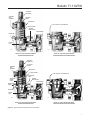
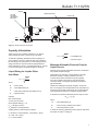
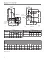
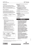
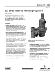
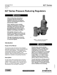
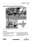
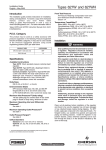
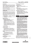
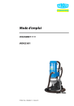
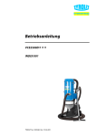
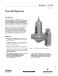
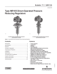
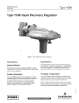
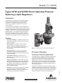
Bulletin 71.1:627W
October 2009
Types 627W and 627WH Direct-Operated Pressure
Reducing Liquid Regulators
Introduction
The Types 627W and 627WH are direct-operated pressure
reducing regulators for liquid service. They are available
in NPS 3/4, 1, and 2 (DN 25 and 50) body sizes and in
a wide range of materials of construction to match most
service conditions.
A control line version is available in either the Type 627W or
the Type 627WH (a higher pressure range unit). Both units are
available with either internal or external downstream pressure
registration. A control line is required for the external pressure
registration version. The control line version has a blocked
throat with an O-ring stem seal and a 1/4 NPT control line
connection in the diaphragm case (Figure 2). The stem seal
separates the body outlet pressure from the diaphragm case.
Features
• Application Versatility—The regulators can be used in
nearly all liquid applications where constant downstream
pressure is required.
• Tamper-Resistant—An adjusting screw locknut
and protective cap (Figure 1) are standard on all
Type 627W regulators to discourage tampering with
the pressure setting.
• Tight Shutoff Capability—A flat-faced disk of
Nylon (PA) or various elastomers provides excellent
shutoff capability.
• Installation Adaptability—The diaphragm case and/or
regulator body can be rotated in any of four positions to
allow regulator installation in locations with limited space.
The regulator may be installed in any position without
affecting operation as long as the spring case vent is
protected from the elements.
• Versatility—The Types 627W and 627WH are available
in six spring ranges, five disk materials, and three
different body materials. The body is available in NPT,
ASME flanged, and EN flanged constructions.
W6309
Figure 1. Type 627W Pressure Reducing Liquid Regulator
Principle of Operation
The Type 627W or 627WH (refer to Figure 2) is a directoperated regulator. On the internal registration version,
downstream pressure is registered internally through the body
to the under side of the diaphragm. When the downstream
pressure is at or above the set pressure, the disk is held
against the seat, and there is no flow through the regulator.
When demand increases, downstream pressure drops slightly
allowing the spring to extend, moving the stem down and the
disk away from the seat. This allows flow through the body to
the downstream system.
Types 627W and 627WH direct-operated regulators are also
available in a downstream control line version. This version has
a stem seal between the body outlet pressure and diaphragm
case. Pressure is registered under the diaphragm through the
1/4 NPT downstream control line connection (Figure 2).
www.fisherregulators.com
D102088X012
• Easy to Maintain—Trim parts can be replaced without removing the regulator body from the pipeline. A two-bolt connection between the body
and diaphragm casing simplifies disassembly
for maintenance.
Bulletin 71.1:627W
Specifications
Available Constructions
Type 627W: Direct-operated pressure reducing
liquid regulator (Figure 2).
Type 627WH: Type 627W with a diaphragm limiter to deliver a higher outlet pressure (Figure 2).
Control Line Option: Type 627W or 627WH
with a stem seal between the body outlet pressure
and diaphragm case. Pressure is measured under
the diaphragm through the 1/4 NPT downstream control line connection (Figure 2).
Body Sizes and End Connection Styles
NPT: 3/4, 1, or 2
CL150, CL300, or CL600 RF Flanged: NPS 1 or 2 (DN 25 or 50)
PN 16, 25, or 40: NPS 1 or 2 (DN 25 or 50)
Maximum Operating Inlet And Outlet Pressure Ranges(1)
See Table 1 for pressures by orifice and spring range
Body Pressure Shell Rating(1)
NPT (Steel): 2000 psig (138 bar)
NPT (Ductile Iron): 1000 psig (69,0 bar) CL600 RF Flanged (Steel): 1500 psig (103 bar)
Maximum Spring And Diaphragm Casing Pressure(1)
See Table 2
Construction Materials
Body: Ductile iron, stainless steel, or steel
Spring Case: Stainless steel, steel, or ductile iron
Diaphragm Case: Ductile iron, stainless steel,
or steel
O-Rings: Nitrile (NBR), Fluorocarbon (FKM),
Ethylenepropylene (EPDM), or elastomeric
Polytetrafluoroethylene (PTFE)
Diaphragm: Nitrile (NBR), Fluorocarbon (FKM),
Ethylenepropylene (EPDM), or PTFE protector
Lever, Lever support, Orifice, and Stem guide:
   Stainless steel
Disk Holder with Valve Disk
Stainless steel with; Nylon (PA), Nitrile (NBR),
Fluorocarbon (FKM), or Ethylenepropylene (EPDM)
Temperature Capabilities(1)
See Table 3
Pressure Registration
Type 627W or 627WH: Internal
Optional: External through 1/4 NPT control line
connection in the diaphragm case
Spring Case Vent Connection
3/4 NPT with removable screened vent assembly
Orifice Sizes
1/4 or 1/2-inch (6,3 or 13 mm)
Approximate Weight
With Ductile Iron or Steel Casings:
10 pounds (5 kg)
Regulator Capacities
Type 627W: See Table 4
Type 627WH: See Table 5
External Dimensions
See Figure 4
Cv Coefficients at 20% Proportional Band (Droop)
Type 627W: See Table 6
Type 627WH: See Table 7
Flow and Sizing Coefficients
See Table 8
Option
Outlet Pressure Gauge (Brass):
0 to 30 psi (0 to 2,1 bar); 0 to 60 psi (0 to 4,1 bar);
0 to 160 psi (0 to 11,0 bar); 0 to 300 psi (0 to 20,7 bar); or 0 to 600 psi (0 to 41,4 bar)
1. The pressure/temperature limits in this Bulletin and any applicable standard or code limitation should not be exceeded.
Installation
Type 627W regulators may be installed in any position, as long
as flow will be in the same direction as that indicated by the
body arrow. The pressure and temperature limitations in the
Specifications table must be observed and the downstream
equipment protected from being overpressured.
Liquid pressure control systems should be designed using good
engineering practices to eliminate quick starting or stopping
of the flow stream, which can produce water hammer. The
regulator should be installed so that the screened spring case
vent is protected from anything that might clog it. To obtain the
published capacities, the inlet and outlet piping should be the
same as the regulator size.
A downstream control line is field installed with the control line
version of the Type 627W or the Type 627WH.
2
Fisher® provides an instruction manual with every regulator
shipped. Refer to this for complete installation, operation, and
maintenance instructions. Included is a complete listing of
individual parts and recommended spare parts.
Monitor Installation
One regulator (worker) is set at the desired downstream
pressure. The other regulator (monitor) is set at a higher
pressure and remains wide open. If the worker regulator fails
open, the monitor regulator controls the downstream pressure
at its setpoint. System lock-up pressure will be the monitor
lock-up pressure (see Figure 3).
Bulletin 71.1:627W
ADJUSTING
SCREW CAP
SCREENED
VENT
ASSEMBLY
ADJUSTING
SCREW
SPRING CASE
1/4 NPT CONTROL LINE CONNECTION
CONTROL SPRING
INTERNAL
REGISTRATION
DISK ASSEMBLY
DIAPHRAGM
PUSHER
POST
W6306-1
W6483-2
DETAILS OF TYPE 627W WITH INTERNAL
DOWNSTREAM REGISTRATION
DETAIL OF TYPE 627W WITH EXTERNAL
DOWNSTREAM PRESSURE REGISTRATION
ADJUSTING
SCREW CAP
ADJUSTING
SCREW
SCREENED
VENT
ASSEMBLY
SPRING CASE
CONTROL SPRING
1/4 NPT CONTROL LINE CONNECTION
DIAPHRAGM
HEAD
DIAPHRAGM
LIMITER
O-RING
INTERNAL
REGISTRATION
DISK ASSEMBLY
DIAPHRAGM
LIMITER
DIAPHRAGM
PUSHER
POST
W6305-1
W5482-1
DETAILS OF TYPE 627WH WITH INTERNAL
DOWNSTREAM REGISTRATION
DETAIL OF TYPE 627WH WITH EXTERNAL
DOWNSTREAM PRESSURE REGISTRATION
Figure 2. Types 627W and 627WH Construction Details
3
Bulletin 71.1:627W
Table 1. Maximum Inlet Pressure, Differential Pressure, and Outlet Pressure Ranges
TYPE
NUMBER
627W
627WH
OUTLET PRESSURE
RANGE CONTROL
SPRING (COLOR)
ORIFICE SIZE,
INCHES (mm)
MAXIMUM INLET PRESSURE, PSIG (bar)
MAXIMUM DIFFERENTIAL PRESSURE,
PSID (bar d)
Elastomer Disk
Nylon (PA) Disk
Elastomer Disk
Nylon (PA) Disk
10 to 20 psig
(0,69 to 1,4 bar)
10B3076X012 (yellow)
1/4 (6,3)
220 (15,2)
420 (29,0)
200 (13,8)
400 (27,6)
1/2 (13)
220 (15,2)
250 (17,2)
200 (13,8)
250 (17,2)
15 to 40 psig
(1,0 to 2,8 bar)
10B3077X012 (green)
1/4 (6,3)
240 (16,5)
440 (30,3)
200 (13,8)
400 (27,6)
1/2 (13)
240 (16,5)
300 (20,7)
200 (13,8)
300 (20,7)
35 to 80 psig
(2,4 to 5,5 bar)
10B3078X012 (blue)
1/4 (6,3)
280 (19,3)
480 (33,1)
200 (13,8)
400 (27,6)
1/2 (13)
280 (19,3)
480 (33,1)
200 (13,8)
400 (27,6)
70 to 150 psig
(4,8 to 10,3 bar)
10B3079X012 (red)
1/4 (6,3)
350 (24,1)
550 (37,9)
200 (13,8)
400 (27,6)
1/2 (13)
350 (24,1)
550 (37,9)
200 (13,8)
400 (27,6)
140 to 250 psig
(9,6 to 17,2 bar)
10B3078X012 (blue)
1/4 (6,3)
450 (31,0)
650 (44,8)
200 (13,8)
400 (27,6)
1/2 (13)
450 (31,0)
500 (34,5)
200 (13,8)
250 (17,2)
240 to 500 psig
(16,5 to 34,5 bar)
10B3079X012 (red)
1/4 (6,3)
700 (48,3)
900 (62,1)
200 (13,8)
400 (27,6)
1/2 (13)
700 (48,3)
750 (51,7)
200 (13,8)
250 (17,2)
Table 2. Maximum Spring and Diaphragm Casing Pressure(1)
MAXIMUM PRESSURE CONDITION
Maximum pressure to spring and diaphragm casings to
prevent leak to atmosphere (internal parts damage may occur)
Maximum pressure to spring and diaphragm casings to prevent
burst of casings during abnormal operation (leak to atmosphere and
internal parts damage may occur)
TYPE 627W
TYPE 627WH
DIAPHRAGM CASING
MATERIAL
Psig
bar
Psig
bar
Ductile Iron
250
17,2
----
----
Steel or Stainless Steel
250
17,2
800
55,2
Ductile Iron
465
32,1
----
----
Steel or Stainless Steel
1500
103
1500
103
All Materials
60
4,1
120
8,3
Maximum diaphragm casing overpressure (above setpoint) to prevent
damage to internal parts
1. If the spring case is pressurized, a metal adjusting screw cap is required. Contact your local Sales Office for details.
Table 3. Elastomer Temperature Ranges
MATERIAL
Nitrile (NBR)
Fluorocarbon (FKM)
Ethylenepropylene (EPDM)
DISK/DIAPHRAGM
Disk
Diaphragm
Disk
Diaphragm
Disk
Diaphragm
TEMPERATURES
°C(1)
-40 to 180
-40 to 82
General
0 to 300
-18 to 149
Not Recommended for Hot
Water Service
-40 to 275
-40 to 135
Not Recommended for
Hydrocarbon Service
Corrosive
Perfluoroelastomer (FFKM)
Disk
0 to 400
-18 to 204
Nylon (PA)
Disk
-40 to 200
-40 to 93
General
PTFE
Diaphragm Protector
-40 to 400
-40 to 204
Corrosive
1. Stainless steel body is rated to -40°F (-40°C). Steel and ductile iron bodies are rated to -20°F (-29°C).
4
USAGE
°F(1)
Bulletin 71.1:627W
MONITOR
WORKING REGULATOR
TYPE 627W
SET HIGHER
THAN WORKING
REGULATOR
CONTROL LINE
INLET
A6623
TYPE 627W
TYPE 627W
Figure 3. Monitor Regulator Schematic
Capacity Information
Tables 4 and 5 give regulating capacities in U.S. GPM of
water (multiply by 0.2271 to convert to m3/h of water).
To determine regulating capacities at pressure settings not
given in Tables 4 and 5 or to determine wide-open capacities
for relief sizing at any inlet pressure, use the Catalog 10 liquid
sizing procedures in conjunction with the appropriate liquid
sizing coefficients (Cv and Km, see Tables 6 through 8). Convert
to m3/h according to the preceding paragraph if necessary.
Liquid Sizing for Liquids Other
than Water
Q = Cv
∆P
G
where:
Q
= Flow in GPM
∆P
= Value differential in psi
Cv
= Valve sizing coefficient (see Tables 6 and 7)
G
= Specific Gravity
Q = 1.18
1/4-inch (6,3 mm) orifice
Glycol (Specific Gravity) = 1.11
Pinlet = 200 psig (13,8 bar)
Pout (setpoint) = 100 psig (6,9 bar)
Capacity based on 20% Droop from setpoint
Pout at full flow = 100 psi setpoint – 20 psi Droop = 80 psi
1.11
= 12.2 GPM Glycol
= 46,2 l/min Glycol
Maximum Allowable Pressure Drop for
Liquid Service
Pressure drops in excess of allowable will result in choked flow
and possible cavitation damage.
Choked flow is the formation of vapor bubbles in the liquid
flowstream causing a crowding condition at the vena
contracta which tends to limit flow through the regulator.
The vena contracta is the minimum cross-sectional area
of the flow stream occurring just downstream of the actual
physical restriction.
Cavitation and flashing are physical changes in the process
fluid. The change is from the liquid state to the vapor state and
results from the increase in fluid velocity at or just downstream
of the greatest flow restriction, normally the regulator orifice.
To determine the maximum allowable pressure drop for water:
Example:
NPS 1 (DN 25) body
120
∆P(allow) = Km (P1)
where:
∆P = Valve differential in psi
Km = Valve recovery coefficient from Table 8
P1 = Valve inlet pressure in psia
To determine maximum allowable pressure drop for fluids other
than water, see Fisher® Catalog 10.
∆P = 200 – 80 = 120 psi
Cv = 1.18 from Table 6
5
Bulletin 71.1:627W
Table 4. Water Capacities(1) for the Type 627W Regulator in GPM (l/min) with or without a downstream control line
OUTLET PRESSURE
RANGE AND CONTROL
SPRING (COLOR)
OUTLET PRESSURE
SETTING
1/4-Inch
(6,3 mm)
Orifice
0,69
15
20
30
60
75
100
150
200
300
400
1,0
1,4
2,1
4,1
5,2
6,9
10,3
13,8
20,7
27,6
2.9
4.0
5.4
8.3
9.4
10
10
10
10
10
(11,0)
(15,1)
(20,4)
(31,4)
(35,6)
(37,9)
(37,9)
(37,9)
(37,9)
(37,9)
6.9 (26,1)
8.7 (32,9)
13 (49,2)
12 (45,4)
12 (45,4)
11 (41,6)
10 (37,9)
10 (37,9)
-------
2.9
4.0
6.0
9.2
10
12
15
18
22
25
(11,0)
(15,1)
(22,7)
(34,8)
(37,9)
(45,4)
(56,8)
(68,1)
(83,3)
(94,6)
7.0 (26,5)
9.2 (34,8)
13 (49,2)
23 (87,1)
23 (87,1)
23 (87,1)
22 (83,3)
20 (75,7)
-------
3.0
4.1
6.0
9.2
10
12
15
18
22
25
(11,4)
(15,5)
(22,7)
(34,8)
(37,9)
(45,4)
(56,8)
(68,1)
(83,3)
(94,6)
7.0 (26,5)
9.2 (34,8)
13 (49,2)
28 (106)
33 (125)
38 (144)
29 (110)
24 (90,8)
-------
1,4
30
50
60
100
150
200
300
400
2,1
3,4
4,1
6,9
10,3
13,8
20,7
27,6
4.8
7.4
8.4
12
15
15
14
12
(18,2)
(28,0)
(31,8)
(45,4)
(56,8)
(56,8)
(53,0)
(45,4)
11 (41,6)
14 (53,0)
14 (53,0)
17 (64,3)
16 (60,6)
16 (60,6)
-------
4.8
7.4
8.4
12
15
17
21
25
(18,2)
(28,0)
(31,8)
(45,4)
(56,8)
(64,3)
(79,5)
(94,6)
11 (41,6)
20 (75,7)
25 (94,6)
32 (121)
42 (159)
43 (163)
-------
4.8
7.4
8.4
12
15
17
21
25
(18,2)
(28,0)
(31,8)
(45,4)
(56,8)
(64,3)
(79,5)
(94,6)
11 (41,6)
20 (75,7)
25 (94,6)
32 (121)
42 (159)
43 (163)
-------
2,8
60
75
100
150
200
300
400
4,1
5,2
6,9
10,3
13,8
20,7
27,6
6.7
8.3
11
14
16
18
20
(25,4)
(31,4)
(41,6)
(53,0)
(60,6)
(68,1)
(75,7)
13 (49,2)
18 (68,1)
19 (71,9)
20 (75,7)
19 (71,9)
19 (71,9)
----
6.7
8.3
11
14
16
21
24
(25,4)
(31,4)
(41,6)
(53,0)
(60,6)
(79,5)
(90,8)
14
23
28
40
49
45
60
(53,0)
(87,1)
(106)
(151)
(185)
(170)
(227)
6.7
8.3
11
14
16
21
24
(25,4)
(31,4)
(41,6)
(53,0)
(60,6)
(79,5)
(90,8)
19 (71,9)
25 (94,6)
31 (117)
40 (151)
49 (185)
45 (170)
----
4,1
75
100
150
200
300
400
5,2
6,9
10,3
13,8
20,7
27,6
6.4
9.2
13
16
20
22
(24,2)
(34,8)
(49,2)
(60,6)
(75,7)
(83,3)
19
20
24
26
25
23
(71,9)
(75,7)
(90,8)
(98,4)
(94,6)
(87,1)
6.4
9.2
13
16
20
22
(24,2)
(34,8)
(49,2)
(60,6)
(75,7)
(83,3)
19
23
36
42
60
60
(71,9)
(87,1)
(136)
(159)
(227)
(227)
6.4
9.2
13
16
20
22
(24,2)
(34,8)
(49,2)
(60,6)
(75,7)
(83,3)
19
24
36
51
60
66
(71,9)
(90,8)
(136)
(193)
(227)
(250)
80
5,5
100
150
200
300
400
6,9
10,3
13,8
20,7
27,6
7.7
12
15
20
23
(29,1)
(45,4)
(56,8)
(75,7)
(87,1)
19
20
24
26
25
(71,9)
(75,7)
(90,8)
(98,4)
(94,6)
7.7
12
15
20
23
(29,1)
(45,4)
(56,8)
(75,7)
(87,1)
21
35
43
60
70
(79,5)
(132)
(163)
(227)
(265)
7.7
12
15
20
23
(29,1)
(45,4)
(56,8)
(75,7)
(87,1)
22
41
49
60
70
(83,3)
(155)
(185)
(227)
(265)
100
6,9
150
200
300
500
10,3
13,8
20,7
34,5
9.4
12
19
26
(35,6)
(45,4)
(71,9)
(98,4)
20
23
25
25
(75,7)
(87,1)
(94,6)
(94,6)
9.6
13
19
26
(36,3)
(49,2)
(71,9)
(98,4)
24
32
44
58
(90,8)
(121)
(167)
(220)
9.6
14
19
26
(36,3)
(53,0)
(71,9)
(98,4)
24
32
50
82
(90,8)
(121)
(189)
(310)
125
8,6
150
200
300
500
10,3
13,8
20,7
34,5
9.0
13
18
25
(34,1)
(49,2)
(68,1)
(94,6)
19
24
29
33
(71,9)
(90,8)
(110)
(125)
9.0
13
18
25
(34,1)
(49,2)
(68,1)
(94,6)
19
29
42
74
(71,9)
(110)
(159)
(280)
9.0
13
18
25
(34,1)
(49,2)
(68,1)
(94,6)
22
31
49
74
(83,3)
(117)
(185)
(280)
150
10,3
200
300
500
13,8
20,7
34,5
11 (41,6)
17 (64,3)
25 (94,6)
40
60
35 to 80 psig
(2,4 to 5,5 bar)
10B3078X012 (blue)
1. Water flow capacities based on a 20% proportional band.
6
25 (94,6)
34 (129)
37 (140)
1/4-Inch
(6,3 mm)
Orifice
11 (41,6)
17 (64,3)
25 (94,6)
1/2-Inch
(13 mm)
Orifice
NPS 2 (DN 50) BODY
bar
20
1/2-Inch
(13 mm)
Orifice
NPS 1 (DN 25) BODY
Psig
10 to 20 psig
(0,69 to 1,4 bar)
10B3076X012 (yellow)
70 to 150 psig
(4,8 to 10,3 bar)
10B3079X012 (red)
NPS 3/4 BODY
bar
Psig
10
15 to 40 psig
(1,0 to 2,8 bar)
10B3077X012 (green)
INLET
PRESSURE
28 (106)
43 (163)
73 (276)
1/4-Inch
(6,3 mm)
Orifice
11 (41,6)
17 (64,3)
25 (94,6)
1/2-Inch
(13 mm)
Orifice
31 (117)
43 (163)
73 (276)
Bulletin 71.1:627W
Table 5. Water Capacities(1) for the Type 627WH Regulator in GPM (l/min) with or without a downstream control line
OUTLET PRESSURE
RANGE AND CONTROL
SPRING (COLOR)
OUTLET PRESSURE
SETTING
NPS 3/4 BODY
NPS 1 (DN 25) BODY
NPS 2 (DN 50) BODY
bar
Psig
bar
1/4-Inch
(6,3 mm)
Orifice
1/2-Inch
(13 mm)
Orifice
1/4-Inch
(6,3 mm)
Orifice
1/2-Inch
(13 mm)
Orifice
1/4-Inch
(6,3 mm)
Orifice
1/2-Inch
(13 mm)
Orifice
10,3
200
250
300
400
500
550
13,8
17,2
20,7
27,6
34,5
37,9
10
14
17
20
23
24
(37,9)
(53,0)
(64,3)
(75,7)
(87,1)
(90,8)
25 (94,6)
31 (117)
33 (125)
34 (129)
-------
11
14
17
21
24
25
(41,6)
(53,0)
(64,3)
(79,5)
(90,8)
(94,6)
25 (94,6)
31 (117)
33 (125)
34 (129)
-------
12
14
17
21
24
25
(45,4)
(53,0)
(64,3)
(79,5)
(90,8)
(94,6)
25 (94,6)
31 (117)
33 (125)
34 (129)
-------
13,8
250
300
400
500
600
17,2
20,7
27,6
34,5
41,4
12
15
19
22
25
(45,4)
(56,8)
(71,9)
(83,3)
(94,6)
30 (114)
36 (136)
44 (167)
-------
12
16
20
22
27
(45,4)
(60,6)
(75,7)
(83,3)
(102)
30 (114)
36 (136)
44 (167)
-------
13
16
20
23
27
(49,2)
(60,6)
(75,7)
(87,1)
(102)
30 (114)
36 (136)
44 (167)
-------
250
17,2
300
400
500
650
20,7
27,6
34,5
44,8
13
18
22
27
(49,2)
(68,1)
(83,3)
(102)
35 (132)
46 (174)
51 (193)
----
13
18
23
27
(49,2)
(68,1)
(87,1)
(102)
51 (193)
52 (197)
58 (220)
----
13
18
22
27
(49,2)
(68,1)
(83,3)
(102)
51 (193)
52 (197)
58 (220)
----
250
17,2
300
400
500
650
20,7
27,6
34,5
44,8
10
15
18
20
(37,9)
(56,8)
(68,1)
(75,7)
25 (94,6)
30 (114)
36 (136)
----
10
16
18
20
(37,9)
(60,6)
(68,1)
(75,7)
25 (94,6)
32 (121)
38 (144)
----
10
16
18
20
(37,9)
(60,6)
(68,1)
(75,7)
25 (94,6)
32 (121)
38 (144)
----
300
20,7
350
400
500
700
24,1
27,6
34,5
48,3
12
15
20
27
(45,4)
(56,8)
(75,7)
(102)
28 (106)
31 (117)
38 (144)
----
12
16
20
27
(45,4)
(60,6)
(75,7)
(102)
28 (106)
32 (121)
39 (148)
----
12
16
20
27
(45,4)
(60,6)
(75,7)
(102)
28 (106)
32 (121)
39 (148)
----
400
27,6
450
500
750
800
31,0
34,5
51,7
55,2
14
18
27
28
(53,0)
(68,1)
(102)
(106)
36 (136)
41 (155)
-------
15
19
27
28
(56,8)
(71,9)
(102)
(106)
33 (125)
42 (159)
-------
15
19
27
28
(56,8)
(71,9)
(102)
(106)
33 (125)
42 (159)
-------
500
34,5
550
600
750
900
37,9
41,4
51,7
62,1
17
19
25
27
(64,3)
(71,9)
(94,6)
(102)
44 (167)
50 (189)
62 (235)
----
17
20
28
28
(64,3)
(75,7)
(106)
(106)
45 (170)
51 (193)
66 (250)
----
17
20
28
28
(64,3)
(75,7)
(106)
(106)
45 (170)
51 (193)
66 (250)
----
Psig
150
140 to 250 psig
(9,6 to 17,2 bar)
10B3078X012 (blue)
INLET
PRESSURE
200
240 to 500 psig
(16,5 to 34,5 bar)
10B3079X012 (red)
1. Water flow capacities based on a 20% proportional band.
7
Bulletin 71.1:627W
Table 6. Cv Coefficients(1) for the Type 627W Regulator with or without a downstream control line
OUTLET PRESSURE
RANGE AND CONTROL
SPRING (COLOR)
OUTLET PRESSURE
SETTING
NPS 2 (DN 50) BODY
bar
1/4-Inch
(6,3 mm)
Orifice
1/2-Inch
(13 mm)
Orifice
1/4-Inch
(6,3 mm)
Orifice
1/2-Inch
(13 mm)
Orifice
1/4-Inch
(6,3 mm)
Orifice
1/2-Inch
(13 mm)
Orifice
0,69
15
20
30
60
75
100
150
200
300
400
1,0
1,4
2,1
4,1
5,2
6,9
10,3
13,8
20,7
27,6
1.09
1.14
1.14
1.14
1.14
1.06
0.88
0.68
0.52
0.50
2.60
2.51
2.76
1.64
1.40
1.12
0.80
0.70
-------
1.10
1.15
1.27
1.27
1.27
1.27
1.27
1.27
1.27
1.27
2.65
2.64
2.87
3.22
2.81
2.41
1.88
1.49
-------
1.15
1.19
1.27
1.27
1.27
1.27
1.27
1.27
1.27
1.27
2.65
2.64
2.87
3.28
3.22
3.20
3.16
3.15
-------
1,4
30
50
60
100
150
200
300
400
2,1
3,4
4,1
6,9
10,3
13,8
20,7
27,6
1.27
1.27
1.27
1.27
1.27
1.13
0.84
0.59
2.96
2.33
2.06
1.81
1.28
1.02
-------
1.27
1.27
1.27
1.27
1.27
1.27
1.27
1.27
3.03
3.48
3.50
3.54
3.59
3.14
-------
1.27
1.27
1.27
1.27
1.27
1.27
1.27
1.27
3.03
3.48
3.50
3.54
3.59
3.16
-------
2,8
60
75
100
150
200
300
400
4,1
5,2
6,9
10,3
13,8
20,7
27,6
1.27
1.27
1.27
1.27
1.27
1.19
0.94
2.49
2.76
2.30
1.82
1.40
1.18
----
1.27
1.27
1.27
1.27
1.27
1.27
1.27
2.56
3.48
3.44
3.66
3.75
3.68
----
1.27
1.27
1.27
1.27
1.27
1.27
1.27
3.48
3.89
3.77
3.66
3.75
3.68
----
4,1
75
100
150
200
300
400
5,2
6,9
10,3
13,8
20,7
27,6
1.22
1.27
1.27
1.27
1.27
1.10
3.61
2.80
2.37
2.11
1.55
1.10
1.25
1.27
1.27
1.27
1.27
1.27
3.61
3.23
3.56
3.44
3.60
3.16
1.25
1.27
1.27
1.27
1.27
1.27
3.61
3.27
3.59
3.68
3.60
3.55
80
5,5
100
150
200
300
400
6,9
10,3
13,8
20,7
27,6
1.27
1.27
1.27
1.27
1.27
3.17
2.78
2.31
1.74
1.15
1.27
1.27
1.27
1.27
1.27
3.48
3.78
3.66
3.64
3.56
1.27
1.27
1.27
1.27
1.27
3.72
3.97
3.78
3.64
3.56
100
6,90
150
200
300
500
10,3
13,8
20,7
34,5
1.12
1.14
1.27
1.27
2.32
2.10
1.67
1.23
1.15
1.18
1.27
1.27
2.85
2.90
2.97
2.82
1.15
1.18
1.27
1.27
2.85
2.90
3.07
3.58
125
8,6
150
200
300
500
10,3
13,8
20,7
34,5
1.27
1.27
1.27
1.27
2.69
2.45
2.04
1.64
1.27
1.27
1.27
1.27
2.75
2.91
2.98
3.68
1.27
1.27
1.27
1.27
3.08
3.05
3.14
3.68
150
10,3
200
300
500
13,8
20,7
34,5
1.27
1.27
1.27
2.81
2.54
1.90
1.27
1.27
1.27
3.18
3.22
3.76
1.27
1.27
1.27
3.47
3.22
3.76
20
40
60
35 to 80 psig
(2,4 to 5,5 bar)
10B3078X012 (blue)
1. Cv Coefficients based on a 20% proportional band.
8
NPS 1 (DN 25) BODY
Psig
10 to 20 psig
(0,69 to 1,4 bar)
10B3076X012 (yellow)
70 to 150 psig
(4,8 to 10,3 bar)
10B3079X012 (red)
NPS 3/4 BODY
bar
Psig
10
15 to 40 psig
(1,0 to 2,8 bar)
10B3077X012 (green)
INLET
PRESSURE
Bulletin 71.1:627W
Table 7. Cv Coefficients(1) for the Type 627WH Regulator with or without a downstream control line
OUTLET PRESSURE
RANGE AND CONTROL
SPRING (COLOR)
OUTLET PRESSURE
SETTING
NPS 3/4 BODY
NPS 1 (DN 25) BODY
NPS 2 (DN 50) BODY
bar
Psig
bar
1/4-Inch
(6,3 mm)
Orifice
1/2-Inch
(13 mm)
Orifice
1/4-Inch
(6,3 mm)
Orifice
1/2-Inch
(13 mm)
Orifice
1/4-Inch
(6,3 mm)
Orifice
1/2-Inch
(13 mm)
Orifice
10,3
200
250
300
400
500
550
13,8
17,2
20,7
27,6
34,5
37,9
1.17
1.20
1.25
1.20
1.17
1.17
2.83
2.71
2.51
2.01
-------
1.20
1.24
1.30
1.27
1.23
1.23
2.83
2.71
2.51
2.01
-------
1.26
1.24
1.30
1.27
1.23
1.23
2.83
2.71
2.51
2.01
-------
200
13,8
250
300
400
500
600
17,2
20,7
27,6
34,5
41,4
1.26
1.30
1.25
1.22
1.22
3.14
3.05
2.80
-------
1.30
1.34
1.27
1.27
1.27
3.14
3.05
2.80
-------
1.34
1.34
1.27
1.27
1.27
3.14
3.05
2.80
-------
250
17,2
300
400
500
650
20,7
27,6
34,5
44,8
1.27
1.27
1.27
1.27
3.46
3.25
2.92
----
1.27
1.27
1.27
1.27
5.10
3.68
3.33
----
1.32
1.28
1.28
1.28
5.10
3.68
3.33
----
250
17,2
300
400
500
650
20,7
27,6
34,5
44,8
1.00
1.07
1.02
1.02
2.46
2.15
2.08
----
1.03
1.10
1.02
1.02
2.52
2.23
2.17
----
1.03
1.10
1.02
1.02
2.52
2.23
2.17
----
300
20,7
350
400
500
700
24,1
27,6
34,5
48,3
1.17
1.22
1.27
1.27
2.63
2.45
2.33
----
1.18
1.25
1.27
1.27
2.69
2.52
2.45
----
1.18
1.25
1.27
1.27
2.69
2.52
2.45
----
400
27,6
450
500
750
800
31,0
34,5
51,7
55,2
1.27
1.38
1.28
1.28
3.16
3.02
-------
1.29
1.40
1.28
1.28
3.23
3.10
-------
1.29
1.40
1.28
1.28
3.23
3.10
------
500
34,5
550
600
750
900
37,9
41,4
51,7
62,1
1.40
1.36
1.34
1.34
3.57
3.51
3.50
----
1.42
1.38
1.38
1.38
3.64
3.60
3.50
----
1.42
1.38
1.38
1.38
3.64
3.60
3.50
----
Psig
150
140 to 250 psig
(9,6 to 17,2 bar)
10B3078X012 (blue)
INLET
PRESSURE
240 to 500 psig
(16,5 to 34,5 bar)
10B3079X012 (red)
1. Cv Coefficients based on a 20% proportional band.
Table 8. Flow and Sizing Coefficients
ORIFICE SIZE, INCHES (mm)
BODY SIZE,
NPS (DN)
Wide-Open CV For Relief Sizing
1/4 (6,3)
1/2 (13)
3/4
1.63
4.87
1 (25)
1.70
5.29
2 (50)
1.66
5.01
Km
1/4 (6,3)
0.76
IEC Sizing Coefficients
1/2 (13)
0.74
XT
FD
1/4 (6,3)
1/2 (13)
0.592
0.962
0.543
0.815
0.620
1.01
FL
1/4 (6,3)
1/2 (13)
1/4 (6,3)
1/2 (13)
0.50
0.50
0.87
0.86
9
Bulletin 71.1:627W
4.25 (108)
DUCTILE IRON
AND 4.69 (119)
STEEL OR SST
4.25 (108) DUCTILE
IRON AND
4.69 (119)
STEEL OR SST
E
3/4 NPT
VENT ASSEMBLY
E
3/4 NPT VENT
CONNECTION
A
1/4 NPT IF
SPECIFIED
5.19 (132)
DUCTILE IRON
AND 5.40 (137)
STEEL OR SST
A
1/4 NPT CONTROL
LINE CONNECTION
(OPTIONAL)
B
B
5.19 (132) DUCTILE
IRON AND 5.40 (137)
STEEL OR SST
11B1443-A
G
D
G
D
10B5885-B
B2088-1
NPT BODY
TYPE 627W
TYPE 627WH
Dimesions, Inches (mm)
Body Sizes,
NPS (DN)
INCHES
(mm)
FLANGED BODY
Dimesions, Inches (mm)
Body Sizes,
NPS (DN)
D
A
B
Ductile
Iron
Steel
or SST
E
G
3/4, 1 (25)
4.06
(103)
1.94
(49)
6.50
(165)
6.75
(171)
9.45
(240)
1.00
(25)
2 (50)
5.00
(127)
2.50
(63)
6.88
(175)
7.12
(181)
10.12
(257)
1.69
(43)
A
B
D
E
G
3/4, 1 (25)
4.06
(103)
1.94
(49)
6.75
(171)
9.88
(251)
1.00
(25)
2 (50)
5.00
(127)
2.50
(63)
7.12
(181)
10.44
(265)
1.69
(43)
TYPE 627W
Flanged Body
Dimesions, Inches (mm)
Body
Size,
NPS (DN)
A
G
CL150
RF
CL300
RF
CL600
RF
PN
16/25/40
CL150
RF
CL300
RF
CL600
RF
PN
16/25/40
D
1 (25)
7.25
(184)
7.75
(197)
8.25
(210)
7.80
(198)
3.62
(92)
3.88
(99)
4.12
(105)
3.90
(99)
6.75
(172)
2 (50)
10.00
(254)
10.50
(267)
11.25
(286)
10.31
(262)
5.00
(127)
5.25
(133)
5.62
(143)
5.16
(131)
7.12
(181)
Figure 4. Dimensions
10
B
E
7.62
(194)
CL150
RF
CL300
RF
CL600
RF
PN
16/25/40
2.12
(54)
2.44
(62)
2.44
(62)
2.27
(58)
3.00
(76)
3.25
(82)
3.25
(82)
3.25
(82)
Bulletin 71.1:627W
TYPE 627WH
Flanged Body
Dimesions, Inches (mm)
Body
Size,
NPS (DN)
A
B
G
CL150
RF
CL300
RF
CL600
RF
CL150
RF
CL300
RF
CL600
RF
PN
16/25/40
D
1 (25)
7.25
(184)
7.75
(197)
8.25
(210)
3.62
(92)
3.88
(99)
4.12
(105)
3.81
(97)
6.75
(172)
2 (50)
10.00
(254)
10.50
(267)
11.25
(286)
5.00
(127)
5.25
(133)
5.62
(143)
5.16
(131)
7.12
(181)
E
7.94
(202)
CL150
RF
CL300
RF
CL600
RF
PN
16/25/40
2.12
(54)
2.44
(62)
2.44
(62)
2.27
(58)
3.00
(76)
3.25
(82)
3.25
(82)
3.25
(82)
Figure 4. Dimensions (continued)
Ordering Information
Application
Construction
When ordering, specify:
Refer to the Specifications section and to each referenced
table; specify the desired selection whenever there is a
choice to be made. The standard assembly position is
shown in Figure 1, but an alternate assembly position may
be factory-ordered or can be accomplished in the field by
unbolting the body or spring case using the instructions
in the appropriate section of the instruction manual. For
dimensions refer to Figure 4.
1.
2.
3.
4.
5.
6.
7.
Type of regulator
Body size
Body material and trim material
Orifice diameter in inches (mm)
Control spring range in psig (bar)
Maximum temperature of process fluid
Desired options
Ordering Guide
Type (Select One)
Spring Case Material (Select One)
627W
627WH (high pressure)
Ductile iron (standard for ductile iron body)***
WCC Steel (standard for steel bodies)***
CF8M Stainless steel (standard for stainless
steel bodies)**
Body Size (Select One)
3/4 NPT***
NPS 1 (DN 25)***
NPS 2 (DN 50)*
Body Material and End Connection Style (Select One)
Ductile Iron (Type 627W Only)
NPT***
WCC Steel
CF8M Stainless Steel
NPT*** NPT **
CL150 RF** CL150 RF*
CL300 RF*** CL300 RF*
CL600 RF*** CL600 RF*
PN 16/25/40*
PN 16/25/40*
Orifice Size (Select One)
1/4-inch (6,3 mm)***
1/2-inch (13 mm)***
Diaphragm Case Material (Select One)
Ductile iron (standard for ductile iron body)***
WCC Steel (standard for steel bodies)***
CF8M Stainless steel (standard for stainless
steel bodies)**
Diaphragm (Select One)
Nitrile (NBR) (standard)***
Fluorocarbon (FKM) - water limited to 180°F (82°C)**
Ethylenepropylene (EPDM)**
O-rings (Select One)
Nitrile (NBR) (standard)***
Fluorocarbon (FKM) - water limited to 180°F (82°C)**
Ethylenepropylene (EPDM)**
Perfluoroelastomer (FFKM)**
11
Bulletin 71.1:627W
Ordering Guide (continued)
Valve Disk (Select One)
PTFE Diaphragm Protector (Optional)
Yes
Nitrile (NBR) (standard)***
Nylon (PA)***
Fluorocarbon (FKM) - water limited to 180°F (82°C)**
Ethylenepropylene (EPDM)**
Spring Range (Select One)
Type 627W
10 to 20 psig (0,69 to 1,4 bar)***
15 to 40 psig (1,0 to 2,8 bar)***
35 to 80 psig (2,4 to 5,5 bar)***
70 to 150 psig (4,8 to 10,3 bar)***
Type 627WH
Pressure:
Maximum Inlet Pressure
Minimum Inlet Pressure
Differential Pressure
Set Pressure
Maximum Flow
Regulators Quick Order Guide
**
*
Internal***
External***
Specification Worksheet
Application:
Specific Use
Line Size
Fluid Type
Specific Gravity
Temperature
Does the Application Require Overpressure Protection? Yes No
140 to 250 psig (9,7 to 17,2 bar)***
240 to 500 psig (16,5 to 34,5 bar)***
***
Pressure Registration (Select One)
Readily Available for Shipment
Allow Additional Time for Shipment
Special Order, Constructed from Non-Stocked Parts.
Consult your local Sales Office for Availability.
Accuracy Requirements:
Less Than or Equal To:
5% 10% 20% 40%
Construction Material Requirements (if known):
Availability of the product being ordered is determined by the component with the
longest shipping time for the requested construction.
Industrial Regulators
Natural Gas Technologies
TESCOM
Emerson Process Management
Regulator Technologies, Inc.
Emerson Process Management
Regulator Technologies, Inc.
Emerson Process Management
Tescom Corporation
USA - Headquarters
McKinney, Texas 75069-1872 USA
Tel: 1-800-558-5853
Outside U.S. 1-972-548-3574
USA - Headquarters
McKinney, Texas 75069-1872 USA
Tel: 1-800-558-5853
Outside U.S. 1-972-548-3574
USA - Headquarters
Elk River, Minnesota 55330-2445 USA
Tel: 1-763-241-3238
Asia-Pacific
Shanghai, China 201206
Tel: +86 21 2892 9000
Asia-Pacific
Singapore, Singapore 128461
Tel: +65 6777 8211
Europe
Bologna, Italy 40013
Tel: +39 051 4190611
Europe
Bologna, Italy 40013
Tel: +39 051 4190611
Gallardon, France 28320
Tel: +33 (0)2 37 33 47 00
Middle East and Africa
Dubai, United Arab Emirates
Tel: +971 4811 8100
Europe
Selmsdorf, Germany 23923
Tel: +49 (0) 38823 31 0
For further information visit www.fisherregulators.com
The Emerson logo is a trademark and service mark of Emerson Electric Co. All other marks are the property of their prospective owners. Fisher is a mark owned by Fisher Controls, Inc., a
business of Emerson Process Management.
The contents of this publication are presented for informational purposes only, and while every effort has been made to ensure their accuracy, they are not to be construed as warranties or
guarantees, express or implied, regarding the products or services described herein or their use or applicability. We reserve the right to modify or improve the designs or specifications of such
products at any time without notice.
Emerson Process Management does not assume responsibility for the selection, use or maintenance of any product. Responsibility for proper selection, use and maintenance of any Emerson
Process Management product remains solely with the purchaser.
©Emerson Process Management Regulator Technologies, Inc., 1994, 2009; All Rights Reserved