1
396P + 396PVP Sensors Instruction Manual
LIQ_MAN_396P_396PVP
August 2013
TUpH Combination pH/ORP Sensors
396P and 396PVP
This page left blank intentionally
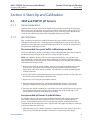
Essential Instructions
Read this page before proceeding
Emerson Process Management designs, manufactures and tests its products to meet many national
and international standards. Because these sensors are sophisticated technical products, you MUST
properly install, use, and maintain them to ensure they continue to operate within their normal specifications. The following instructions MUST be adhered to and integrated into your safety program
when installing, using, and maintaining Rosemount Analytical products. Failure to follow the proper
instructions may cause any one of the following situations to occur: Loss of life; personal injury; property damage; damage to this sensor; and warranty invalidation.
• Read all instructions prior to installing, operating, and servicing the product.
• If you do not understand any of the instructions, contact your Emerson Process Management
representative for clarification.
• Follow all warnings, cautions, and instructions marked on and supplied with the product.
• Inform and educate your personnel in the proper installation, operation, and maintenance of the
product.
• Install your equipment as specified in the Installation Instructions of the appropriate Instruction
Manual and per applicable local and national codes. Connect all products to the proper electrical
and pressure sources.
• To ensure proper performance, use qualified personnel to install, operate, update, program, and
maintain the product.
• When replacement parts are required, ensure that qualified people use replacement parts specified by Emerson Process Management. Unauthorized parts and procedures can affect the
product's performance, place the safe operation of your process at risk, and VOID YOUR
WARRANTY. Look-alike substitutions may result in fire, electrical hazards, or improper operation.
• Ensure that all equipment doors are closed and protective covers are in place, except when maintenance is being performed by qualified persons, to prevent electrical shock and personal injury.
The information contained in this document is subject to change without notice.
DANGER: HAZARDOUS AREA INSTALLATION
Installations near flammable liquids or in hazardous area locations must be carefully evaluated by
qualified on site safety personnel. This sensor is not Intrinsically Safe or Explosion Proof.
To secure and maintain an intrinsically safe installation, the certified safety barrier, transmitter, and
sensor combination must be used. The installation system must comply with the governing approval
agency (FM, CSA or BASEEFA/CENELEC) hazardous area classification requirements. Consult your
analyzer/transmitter instruction manual for details.
Proper installation, operation and servicing of this sensor in a Hazardous Area Installation is entirely
the responsibility of the user.
CAUTION: SENSOR/PROCESS APPLICATION COMPATIBILITY
The wetted sensor materials may not be compatible with process composition and operating conditions. Application compatibility is entirely the responsibility of the user.
ATEX DIRECTIVE: Special Conditions for safe use
1. All pH/ORP sensors have a plastic enclosure which must only be cleaned with a damp cloth to avoid
the danger due to a build up of an electrostatic charge.
2. All pH/ORP sensor Models are intended to be in contact with the process fluid and may not meet the
500V r.m.s. a.c. test to earth. This must be taken into consideration at installation.
CAUTION: SENSOR/PROCESS APPLICATION COMPATIBILITY
The wetted sensor materials may not be compatible with process composition and operating conditions.
Application compatibility is entirely the responsibility of the user.
CAUTION: SENSOR/PROCESS APPLICATION COMPATIBILITY
The wetted sensor materials may not be compatible with process composition and operating conditions.
Application compatibility is entirely the responsibility of the user.
About This Document
This manual contains instructions for installation and operation of the 396P and 396PVP Sensors. The
following list provides s concerning all revisions of this document.
Rev. Level
A
B
Date
2/2013
8/2013
Notes
Manual updated with SMART sensor information.
Wiring diagrams updated.
396P + 396PVP Sensors Instruction Manual
LIQ_MAN_396P_396PVP
Table of Contents
August 2013
Contents
Section 1: Description and Specifications
1.1 Features and Applications ......................................................................................1
1.2 Specifications-General ...........................................................................................3
1.3 Ordering Information .............................................................................................4
Section 2: Installation
2.1 Unpacking and Inspection......................................................................................7
2.2 Mounting...............................................................................................................7
Section 3: 396P-01 Wiring
3.1 General ...............................................................................................................13
Section 4: 396P-02 & 396PVP Wiring
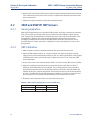
4.1 General ...............................................................................................................21
Section 5: Start-Up and Calibration
5.1 396P & 396PVP pH Sensors ..................................................................................31
5.2 396P & 396PVP ORP Sensors................................................................................32
Section 6: Maintenance
6.1 General Information.............................................................................................33
6.2 Automatic Temperature Compensator .................................................................33
6.3 396P & 396PVP pH Sensors ..................................................................................33
6.4 396P & 396PVP ORP Sensors................................................................................34
Section 7: Diagnostics and Troubleshooting
7.1 56/1056/1057/1066/54e/81/3081/4081/5081/Xmt
Diagnostics and Troubleshooting .........................................................................37
7.2 Troubleshooting without Advanced Diagnostics ..................................................38
Section 8: Return of Material
8.1 General ................................................................................................................43
8.2 Warranty Repair ..................................................................................................43
8.3 Non-Warranty Repair ..........................................................................................43
Table of Contents
i
Table of Contents
396P + 396PVP Sensors Instruction Manual
August 2013
LIQ_MAN_396P_396PVP
This page left blank intentionally
ii
Table of Contents
396P + 396PVP Sensors Instruction Manual
Section 1: Description and Specifications
LIQ_MAN_396P_396PVP
August 2013
Section 1: Description and Specifications
1.1
Features and Applications
TUpH™ pH/ORP-sensors are now offered with SMART capabilities. SMART option becomes
enabled when used with the 1056, 1057, 1066, and 56 Analyzers and on 6081P wireless transmitter. The pH-loop capabilities include auto-recognition of the SMART sensor, automatic upload
of calibration data and associated time stamp, historical recording of pH diagnostics (slope,
offset, reference impedance, glass impedance). This trending data allows technicians to predict
frequency of maintenance and estimate sensor life for a particular process condition. Additional
SMART features include factory calibration, resetting SMART sensor calibration data with user
menus, and manufacturing information.
The TUpH large area reference junction for minimum maintenance requirements: The reference
junction provides an electrical connection between the reference electrode and the sample, and
helps maintain a stable reference potential, regardless of the change in sample pH. The TUpH
reference electrode junction, the entire plastic tip surrounding the glass pH electrode, maintains
a steady reference signal even in the dirtiest of applications because it resists plugging (a common
cause of pH signal drift). This large reference junction area is made of micron sized reference
pathways used for ionic exchange so it resists plugging by large particles and will continue to send
a steady pH signal, even in the dirtiest of applications. The TUpH reference junction technology
has been field-proven for minimum maintenance requirements.
The TUpH helical reference pathway stops reference poisoning. Ions diffuse through the reference
pathways and a charge is passed to the reference element. The reference element must be
protected from contamination by poisoning ions such as sulfide, mercury, cyanide, and ammonia
or else the pH signal will drift. The TupH sensor's long internal helical reference pathway hinders
and slows down the rate of contaminants migrating to the reference element therefore providing
for a longer sensor life.
The entire line of TUpH model sensors now incorporate the new SILCORE™ technology contaminant barrier. This triple-seal barrier prevents moisture and material impurities from migrating to
the pH sensor’s reference electrode’s metal lead wire. By preventing these contaminants from
compromising the integrity of the pH measurement, sensor life is increased, especially at higher
temperatures where increased migrations occur. In addition, the SILCORE technology provides
added protection against sensor failure due to vibrations and shock by transferring damaging
energy away from the glass-to-metal seal.
The AccuGLASS™ pH glass formulations exceed industry standards. The AccuGlass pH glass is a
result of many years of glass research resulting in a formulation which has been found to increase
the life of the sensor. Unlike other pH glasses presently on the market, this glass resists cracking
especially at higher temperatures and reduces sodium ion error commonly found in high pH
applications. Overall, the AccuGlass formulation enhances the sensor performance to measure pH
more accurately and have a longer sensor life than ever before.
A choice of flat or hemi glass pH glass electrodes is available to best meet various application
needs. Flat glass is advantageous in abrasive or coating applications that etch or build up on glass,
respectively. In coating applications, such as slurries, the flat surface allows the process flow to
act as a scrubbing agent to reduce coating and maintenance. In abrasive applications pitting from
silicates and other similar materials is minimized by the flat glass surface to provide longer sensor
life. Flat glass sensors are offered with a flat tip which is flush with the flat glass. The hemi bulb
glass is ideal for general purpose use and for those processes requiring greater accuracy over the
entire pH range. All hemi bulb sensors are offered with a standard shrouded tip which completely
surrounds the glass bulb for protection against solids. An optional slotted tip is also available and
Description and Specifications
1
Section 1: Description and Specifications
August 2013
396P + 396PVP Sensors Instruction Manual
LIQ_MAN_396P_396PVP
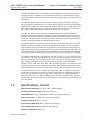
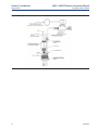
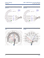
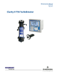
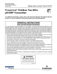
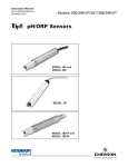
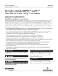
FIGURE 1-1. Cross Section Diagram of the TUpH Reference Technology. All TUpH sensors are designed with a
large area reference junction, helical reference pathway, and an AccuGlass pH glass bulb. This sensor technology
ensures superior performance while only requiring minimal maintenance.
allows the process to flow by the glass electrode for accurate and reliable pH measurement. Both
pH glass bulbs — the standard hemi or optional flat pH glass — are exceptional for increased resistance to high temperature and other effects of aging for longer life.
The TUpH reference junction and helical pathway combined with the AccuGLASS pH glass
performs exceptionally well in dirty, high solid applications and requires only minimum maintenance. This is the toughest pH sensor on the market and is still unmatched by all other pH
sensors. The constant increase in demand for the TUpH sensor proves it's success as the best
process industry pH sensor.
All TUpH sensor models have been specifically designed for improved life in harsh, dirty, and abrasive applications such as lime slurry, waste treatment, paper machine headbox, and pigment/dye
applications, where large quantities of suspended solids are present. Various sensor materials,
depending on the sensor model, are available for a variety of different application needs.
SMART is the standard option. A preamplifier converts the high impedance pH signal into a
stable, noise-free signal and must be used with all pH sensors. An integral SMART preamplifier
stores calibration information and can be built into the sensor when ordering the SMART preamplifier option. Otherwise, a standard preamplifier can be used in a junction box or built into the
analyzer/transmitter. All integral preamplified SMART TupH Sensors are compatible with all Rosemount Analytical instruments.
The 396VP, 396PVP, and 396RVP are offered with a watertight VP sensor-to-cable connector
which eliminates rewiring and cable twisting when replacing sensors. The VP (Variopol) multiple
pin connector is an integral part of each sensor model and uses a mating VP cable. Once the cable
is installed and wired to the analyzer, sensors are easily replaced without replacing the cable,
without rewiring the analyzer (if the replacement sensor is the same as its predecessor). Also the
sensor can be disconnected from the cable before removal from the process which eliminates
cable twisting. VP8 cable assemblies work with all VP sensors. VP8 wiring is standard across all
pH sensor families. VP8 is required when used with SMART preamplified sensors.
2
Description and Specifications
396P + 396PVP Sensors Instruction Manual
Section 1: Description and Specifications
LIQ_MAN_396P_396PVP
August 2013
The 396P and 396PVP sensors are available in two configurations: the standard shrouded tip, in
which the pH glass is completely recessed within the reference junction for abrasive or rough
applications, and the optional slotted tip with a partially exposed pH glass for viscous or low flow
applications.
The 396P and 396PVP sensors feature a titanium solution ground, constructed in an annular
design around the pH/ORP electrode. The solution ground provides advanced sensor diagnostics
for preventative maintenance when used with Rosemount Analytical 54e, 56, 1056, 1057, 5081,
6081, 1066, and XMT instruments. In addition, the Model 396P sensor can be used with most
non-diagnostic Rosemount Analytical and other manufacturers’ instruments.
The 396P and 396PVP sensor is housed in a molded polypropylene body with EPDM seals,
making it virtually indestructible and chemically resistant. Complete encapsulation eliminates
leakage or high humidity problems traditionally found in other pH/ORP designs. The simplified
construction, designed with user convenience in mind, does not require electrolyte (KCl) replenishment or any high maintenance troubleshooting procedures.
The 396 and 396VP TUpH Sensors are housed in a stainless steel body with optional 1" threaded
connector suitable for insertion, submersion or flow through installation. The sensor includes a
general purpose glass pH electrode in the standard bulb or optional flat glass configuration. The
TUpH reference has a large area polypropylene junction with a gel filled reference electrolyte. The
396 and 396VP TUpH are available with an optional SMART integral preamplifier when choosing
the 396VP-55 option. Automatic temperature compensation is standard 3K Balco or Pt 100 RTD.
The 396R and 396RVP Sensors are designed for use with a 1-1/4 in. or 1-1/2 in. ball valve for hot
tap installation. The 396R and 396RVP are constructed of molded polypropylene housed in a titanium tube with EPDM seals to provide maximum chemical resistance. The sensors feature a titanium solution ground used for advanced sensor diagnostics when used with Rosemount
Analytical 54e, 56, 1056, 1057, 5081, 6081, 1066, and XMT instruments. These advanced sensor
diagnostics provide preventative maintenance by notifying the operator of the need for replacement and cleaning of an aged or fouled sensor, thus allowing continuous optimum performance.
The Rosemount Analytical 54e, 56, 1056, 1057, 1066, 5081, 6081, and XMT instruments offer
advanced sensor diagnostics to provide preventative maintenance by notifying the operator of
the need for replacement and cleaning of an aged or fouled sensor, thus allowing continuous
optimum performance. The 396R and 396RVP sensors also feature a slotted tip for protection
from breakage while allowing the process to flow by the glass electrode for accurate and reliable
pH measurement.
1.2
Specifications - General
Measurements and Ranges: pH*: 0-14 / ORP: -1500 to 1500 mv
Available pH ACCUGLASS Types: GPLR hemi or flat glass
Wetted Materials: Titanium, Polypropylene, EPDM, glass; platinum (ORP only)
Process Connection: 1 in. MNPT front and rear facing threads
Temperature Range: 0-100°C (32-212°F)
Pressure Range-Hemi bulb: 100-1135 kPa [abs] (0-150 psig)
Pressure Range-Flat bulb: 100-790 kPa [abs] (0-100 psig)
Minimum Conductivity: 100 μS/cm
Description and Specifications
3
Section 1: Description and Specifications
396P + 396PVP Sensors Instruction Manual
August 2013
LIQ_MAN_396P_396PVP
Integral Cable 396P: Code 01 - 25 ft; Code 02 - 15 ft coaxial / 396PVP: none - must use mating
VP cable
Preamplifier Options: Remote or Integral SMART preamplifier
Weight/Shipping Weight: 0.45 kg/0.9 kg (1 lb/2 lb)
Weight/Shipping Weight: 0.45 kg/0.9 kg (1 lb/
*Percent Linearity
pH Range
396 / 396VP
GPHT Hemi
396P / 396PVP
GPHT Flat
GPHT Hemi
396R / 396RVP
GPLR Flat
GPHT Hemi
GPHT Flat
0-2 pH
94%
95%
94%
–
94%
93%
2-12 pH
99%
99%
97%
98%
97%
98%
12-13 pH
97%
96%
98%
95%
98%
95%
13-14 pH
92%
–
98%
–
98%
–
1.3
Ordering Information
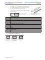
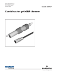
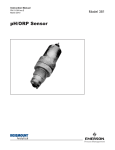
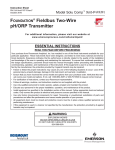
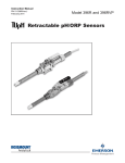
The 396P Sensor is housed in a molded reinforced polypropylene body with 1 in. MNPT threads suitable for insertion,
submersion or flow through installation. The sensor includes a
general purpose pH electrode or a platinum ORP electrode, a
reference junction and a solution ground. The 396P comes
standard with a recessed electrode; an optional slotted tip is
also available. In addition, the 396P features an optional integral hermetically sealed preamplifier and 15 ft or 25 ft cable
lengths. Automatic temperature compensation, Pt 100 or 3K
Balco, is standard with the 396P.
The 396P insertion/submersion sensor
shown with the fully recessed bulb
(standard option).
396P TUpH INSERTION/SUBMERSION POLYPROPYLENE pH/ORP SENSOR
CODE
01
PREAMPLIFIER/CABLE (Required Selection)
With integral SMART preamplifier, 25 ft (7.6m) cable
02
Without integral preamplifier, 15 ft (4.6m) cable
CODE
10
MEASURING ELECTRODE TYPE (Required Selection)
GPLR hemi bulb, General Purpose Low Resistivity (0-14 pH)
12
ORP
13
GPLR flat bulb, General Purpose Low Resistivity (2 - 13 pH)
CODE
50
ANALYZER/TC COMPATIBILITY (Required Selection)
For 1181 (3K TC)
54
For 1054A/B, 2054, 2081 (Pt 100 RTD)
55
For 54e, 3081, 81, 4081, 1055, 5081, Xmt (PT-100 RTD)
CODE
41
396P
OPTIONAL SELECTION
Slotted Tip (not available on flat bulb sensors)
-
01
-
10
-
55
EXAMPLE
NOTE: The 396P is also compatible with Model SCL-P/Q (option 02-54 only).
4
Description and Specifications
396P + 396PVP Sensors Instruction Manual
Section 1: Description and Specifications
LIQ_MAN_396P_396PVP
August 2013
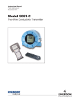
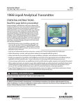
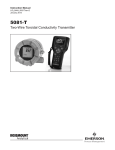
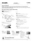
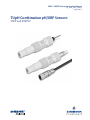
The 396PVP Sensor has similar features to the 396P. However,
the 396PVP is offered with the Variopol (VP) connector and
uses a mating VP cable (purchased separately).
A Variopol cable is required for all new installations. See below
for cable selection.
Variopol connector shown with
mating variopol cable receptacle
The 396PVP insertion/ submersion sensor
with the VP (Variopol) connector
396PVP TUpH INSERTION/SUBMERSION POLYPROPYLENE pH/ORP SENSOR
CODE
10
12
13
MEASURING ELECTRODE
pH GPLR Glass, General Purpose Low Resistivity (0 - 14 pH)
ORP
GPLR Flat Bulb, General Purpose Low Resistivity (2 - 13 pH)
CODE
50
54
55
MEASURING ELECTRODE
For use with Model 1181pH/ORP (3K TC)
For use with Models: 1054, 2054; Series 2081 (Pt-100)
For use with Models: 54, 56, 1055, 1056, 1057, 81,3081, 4081, 5081, 6081 XMT (Pt-100)
CODE
–
41
OPTIONAL
No Selection
Slotted Tip
CODE
–
70
PREAMPLIFIER OPTION
No Preamplifier
With Integral Smart Preamplifier for 396PVP; available with 396PVP-10-55 and 396PVP-13-55 only
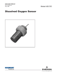
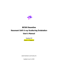
Examples of all sensing tip offerings
Shrouded Tip is
standard on all
hemi bulb sensors
Optional Slotted Tip
is available on all hemi
bulb sensors, ordered
as option -41
Description and Specifications
Flat Tip is available
with flat glass bulb
sensors
5
Section 1: Description and Specifications
396P + 396PVP Sensors Instruction Manual
August 2013
LIQ_MAN_396P_396PVP
Accessories
Connector cable, VP8 (required for all first time installations of VP sensors)
24281-00
15 ft. (4.6m) VP8 cable
24281-01
25 ft. (7.6m) VP8 cable
24281-03
50ft (15.2m) VP8 Cable
24281-04
100ft (30.5m) VP8 Cable
24281-06
10ft (3.0m) VP8 Cable
24281-07
20ft (6.1m) VP8 Cable
24281-08
30ft (9.1m) VP8 Cable
Remote Junction Boxes and Mounting Brackets; for use when standard cable lengths need to be extended
23555-00
Junction Box; contains preamplifier for 54e, 56, 1055, 1056, 1057, 1066, 3081, 4081, 5081, 6081, XMT
23550-00
Junction Box with board for point-to-point cable extension; use with sensors containing integral preamplifiers
2002565
Mounting Bracket Kit with mounting plate and U-bolts; use with PN 23555-00 or 23550-00 junction boxes
Extension Cables (required when using a remote junction box)
23646-01
Extension Cable, 11-conduit with shields, wires prepared for easy installation, per foot (or meter); best choice for easiest
installation
9200273
Extension Cable, 11-conduit with shield, raw cable (user must cut and prepare cable ends), per foot (or meter)
Calibration Accessories
9210012
Buffer Solution, pH 4.01, 16 oz (473 ml)
9210013
Buffer Solution, pH 6.86, 16 oz (473 ml)
9210014
Buffer Solution, pH 9.18, 16 oz (473 ml)
R508-8OZ
ORP Standard, 475mV, 8oz (236 ml)
Mounting Assemblies
6
11275-01
Handrail Mounting Assembly; includes a 6 ft straight pipe, pipe coupling, 6 ft long sweep pipe, unistrut, pipe clamps, and
mounting channels
2002011
CPVC flow through Tee, 1-1/2" NPT process connections
24091-00
Low Flow Cell with 1/4 inch inlet and outlet
915240-03
Tee, Flow-through, 2" PVC tee with " NPT process connections and mounting adapter to eliminate cable twisting
915240-04
Tee, Flow-through, 2" PVC tee with 1" NPT process conections and mounting adapter to eliminate cable twisting
915240-05
Tee, Flow-through, 2" PVC tee with 1 " NPT process connections and mounting adapter to eliminate cable twisting
12707-00
Jet Spray Cleaner; for use with water or air cleaning using interval timer from instrument
Description and Specifications
396P + 396PVP Sensors Instruction Manual
LIQ_MAN_396P_396PVP
Section 2: Installation
August 2013
Section 2: Installation
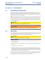
2.1
Unpacking and Inspection
Inspect the outside of the carton for any damage. If damage is detected, contact the carrier
immediately. Inspect the hardware. Make sure all the items in the packing list are present and in
good condition. Notify the factory if any part is missing. If the sensor appears to be in satisfactory
condition, proceed to Section 2.2, Mounting.
NOTE: Save the original packing cartons and materials as most carriers require proof of damage
due to mishandling, etc. Also, if it is necessary to return the sensor to the factory, you must pack
the sensor in the same manner as it was received. Refer to Section 6.0 for return instructions. If
the sensor is to be stored, the vinyl boot should be filled with pH buffer solution and replaced on
sensor tip until ready to use.
CAUTION
Buffer solution, in the vinyl boot, may cause skin or eye irritation.
WARNING
Glass electrode must be wetted at all times (in storage and in line) to maximize sensor life.
2.2
Mounting
The sensor has been designed to be located in industrial process environments. Temperature and
pressure limitations must not be exceeded at any time. A caution label regarding this matter is
attached to the sensor. Please do not remove the label. See Figure 2-1.
CAUTION
Internal electrolyte fill solution may cause skin or eye irritation.
Mounting Guidelines:
1. Shake the sensor in a downward motion to remove any air bubbles that may be present inside
the tip of the pH glass.
2. Do not install the sensor on the horizontal. The sensor must be 10° off the horizontal to ensure
accuracy.
3. Do not install the sensor upside down.
4. Air bubbles may become trapped in the sensor end between the glass bulb and the sensor
body. This problem is most commonly encountered in areas of low flow or during calibration.
Shake the probe while immersed in solution to remove bubbles. This problem can be avoided
by ordering the sensor with the slotted tip (option -41).
In most cases, the pH sensor can simply be installed as shipped and readings with an accuracy of
± 0.6 pH may be obtained. To obtain greater accuracy or to verify proper operation, the sensor
must be calibrated as a loop with its compatible analyzer or transmitter.
Installation
7
Section 2: Installation
396P + 396PVP Sensors Instruction Manual
August 2013
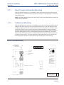
2.2.1
LIQ_MAN_396P_396PVP
Flow Through and Insertion Mounting
396P and 396PVP Sensors have a 1-inch MNPT process connection at the front of the sensor for
mounting into a 1-1/2 inch tee or the process pipes. See Figure 2-2 through Figure 2-7 for installation configurations.
NOTE: LARGE PIPE WRENCHES MUST NOT BE USED TO TIGHTEN THE SENSOR INTO A FLANGE OR
OTHER TYPE OF MOUNTING.
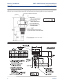
2.2.2
Submersion Mounting
396P and 396PVP Sensors also have a 1 inch MNPT process connection at the back of the sensor.
Utilizing a standard 1 inch union, the sensor may be mounted to a 1 inch SCH 80 CPVC or PVDF
standpipe. Tapered pipe threads in plastic tend to loosen after installation. It is therefore recommended that Teflon1 tape be used on the threads and that the tightness of the connection be
checked frequently to assure that no loosening has occurred. To prevent rain water or condensation from running into the sensor, a weatherproof junction box is recommended. The sensor
cable must be run through a protective conduit for isolation from electrical interference or physical abuse from the process. The sensor should be installed within 80° of vertical, with the electrode facing down. The sensor’s cable should not be run with power or control wiring.
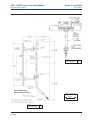
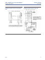
Figure 2-1. Dimensional Drawing
SENSOR CABLE
(OR VP CONNECTOR
- NOT SHOWN)
MILLIMETER
INCH
DWG. NO.
REV.
40396P01
8
D
Installation
396P + 396PVP Sensors Instruction Manual
Section 2: Installation
LIQ_MAN_396P_396PVP
August 2013
Figure 2-2. Flow-Through Tee with Adapter (PN 915240-xx*)
MILLIMETER
INCH
xx*
process Connection
Threads
3/4 inch
1 inch
1-1/2 inch
03
04
05
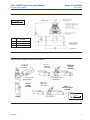
Figure 2-3. Flow-Through and Insertion Installations
1-1/2” x 1”
Reducing
Bushing
1-1/2” x 1”
Reducing
Bushing
1-1/2” Pipe Tee
PN 2002011
aNgLE
fLow
sHowN
sTRaIgHT
fLow
sHowN
1-1/2” Pipe Tee
PN 2002011
1-1/2” x 1”
Reducing
Bushing
pIpE “y”
INsTaLLaTIoN
sHowN
wHEN INCH aND METRIC DIMs
aRE gIVEN
fLow
Installation
1-1/2” PiPE “Y”
MILLIMETER
INCH
9
Section 2: Installation
August 2013
396P + 396PVP Sensors Instruction Manual
LIQ_MAN_396P_396PVP
Figure 2-4. 396P with Insertion Mounting Adapter (PN 23242-02). Not for use with 396PVP. Mounting adapter
allows for sensor removal without twisting or disconnecting interconnecting cable for ease of maintenance.
DWG. NO.
40396P02
REV.
A
Figure 2-5. Low flow cell PN 24091-00
10
Installation
396P + 396PVP Sensors Instruction Manual
Section 2: Installation
LIQ_MAN_396P_396PVP
August 2013
Figure 2-6. Submersion Installations
DWG. NO.
40396P03
REV.
A
Handrail Mounting
assembly pN 11275-01
wHEN INCH aND METRIC DIMs
aRE gIVEN
MILLIMETER
INCH
DWG. NO.
40396P04
Installation
REV.
A
11
Section 2: Installation
August 2013
396P + 396PVP Sensors Instruction Manual
LIQ_MAN_396P_396PVP
Figure 2-7. Spray Wash Assembly PN 4091-00
12
Installation
396P + 396PVP Sensors Instruction Manual
Section 3: Wiring
LIQ_MAN_396P_396PVP
August 2013
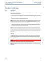
Section 3: Wiring
3.1
General
Figures in this section provide the guidelines for wiring the 396P-01 sensor to various
Analyzer/Transmitter instruments.
To determine which wiring guideline to use, locate the model number of the sensor to be installed.
1. If the cable needs to be extended, use a high quality eleven conductor double shielded instrument cable available from Rosemount Analytical. Refer to Table 3-1 for the appropriate junction box to use and the corresponding wiring details.
NOTE: If the cable is too long, loop up the excess cable. If the cable has to be shortened, cut and
terminate each conductor neatly and make sure that the overall (outermost) drain wire is not
shorted out with either of the two inner drain wires (shields).
2. Signal cable should be run in a dedicated conduit (preferably an earth grounded metallic
conduit) and should be kept away from AC power lines. For your convenience, a wire nut kit is
furnished (in a plastic bag wrapped around the cable).
NOTE: For maximum EMI/RFI protection when wiring from the sensor to the junction box, the
outer braid of the sensor should be connected to the outer braided shield of the extension cable.
The outer braid of the extension cable to the instrument must be terminated at earth ground or
by using an appropriate metal cable gland fitting that provides a secure connection to the instrument cable.
Wiring
The 396P and 396PVP has an optional built-in preamplifier and is offered with a shielded cable.
The cable should be handled carefully and kept dry and free of corrosive chemicals at all times.
Extreme care should be used to prevent it from being twisted, damaged or scraped by rough,
sharp edges or surfaces.
DANGER
DO NOT CONNECT SENSOR CABLE TO POWER LINES. SERIOUS INJURY MAY RESULT.
NOTE: Remove electrical tape or shrink sleeve from gray reference wire before connecting wire
to terminal.
Wiring
13
Section 3: Wiring
396P + 396PVP Sensors Instruction Manual
August 2013
LIQ_MAN_396P_396PVP
NOTE
For additional wiring information on this product, including sensor combinations not shown here, please refer to either our
online wiring programs or the Manual DVD enclosed with each product.
1056, 1057, 56, 5081, 6081, 54e, and XMT :
http://www3.emersonprocess.com/raihome/sp/liquid/wiring/XMT/
1066 and sensors with SMART preamps:
http://www2.emersonprocess.com/en-US/brands/rosemountanalytical/Liquid/Sensors/Pages/ Wiring_Diagram.aspx
1055:
http://www3.emersonprocess.com/raihome/sp/liquid/wiring/1055/
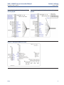
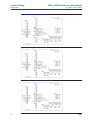
Figure 3-1. Wiring for 396P-01 (Gray Cable)
and 54e pH/ORP
Figure 3-2. Wiring for 396P-01 (Blue Cable) and 54e
pH/ORP
Figure 3-3. Wiring for 396P-02 (Gray Cable)
and 54e pH/ORP
Figure 3-4. Wiring for 396P-02 (Blue Cable) and 54e
pH/ORP
14
Wiring
396P + 396PVP Sensors Instruction Manual
LIQ_MAN_396P_396PVP
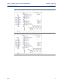
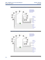
Figure 3-5. Wiring for 396PVP (Gray Cable)
and 54e pH/ORP
Section 3: Wiring
August 2013
Figure 3-6. Wiring for 396PVP (Blue Cable) and 54e
pH/ORP
Figure 3-7. Wiring for 396P-01 and 1055
Wiring
15
Section 3: Wiring
396P + 396PVP Sensors Instruction Manual
August 2013
LIQ_MAN_396P_396PVP
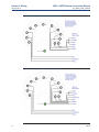
Figure 3-8. Wiring for 396P-02 and 1055
Figure 3-9. Wiring for 396PVP and 1055
Figure 3-10. Wiring for Dual 396P-01 and 1055
16
Wiring
396P + 396PVP Sensors Instruction Manual
LIQ_MAN_396P_396PVP
Section 3: Wiring
August 2013
Figure 3-11. Wiring for Dual 396P-02 and 1055
Figure 3-12. Wiring for Dual 396PVP and 1055
Wiring
17
Section 3: Wiring
August 2013
396P + 396PVP Sensors Instruction Manual
LIQ_MAN_396P_396PVP
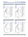
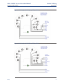
Figure 3-13. Wiring for 396P-01 (Gray Cable) and
1056/56
Figure 3-14. Wiring for 396P-01 (Blue Cable) and
1056/56
Figure 3-15. Wiring for 396P-02 (Gray Cable) and
1056/56
Figure 3-16. Wiring for 396P-02 (Blue Cable) and
1056/56
18
Wiring
396P + 396PVP Sensors Instruction Manual
Section 3: Wiring
LIQ_MAN_396P_396PVP
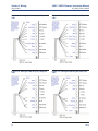
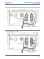
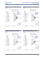
Figure 3-17. Wiring for 396PVP (Gray Cable) and
1056/56
August 2013
Figure 3-18. Wiring for 396P-01 (Blue Cable) and
1056/56
Figure 3-19. Wiring for 396VP-70 (Blue Cable) and 1056/1057/56
Wiring
19
Section 3: Wiring
August 2013
396P + 396PVP Sensors Instruction Manual
LIQ_MAN_396P_396PVP
Figure 3-20. Wiring for 396P-01 (Gray Cable) and
1057
Figure 3-21. Wiring for 396P-01 (Blue Cable) and
1057
Figure 3-22. Wiring for 396P-02 (Gray Cable) and
1057
Figure 3-23. Wiring for 396P-02 (Blue Cable) and
1057
20
Wiring
396P + 396PVP Sensors Instruction Manual
LIQ_MAN_396P_396PVP
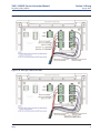
Figure 3-24. Wiring for 396PVP (Gray Cable) and
1057
Section 3: 3Wiring
August 2013
Figure 3-25. Wiring for 396PVP (Blue Cable) and
1057
Figure 3-26. Wiring for 396P-01 and 1066
Wiring
21
Section 3: Wiring
August 2013
396P + 396PVP Sensors Instruction Manual
LIQ_MAN_396P_396PVP
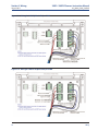
Figure 3-27. Wiring for 396P-01 (Blue Cable) and 1066
Figure 3-28. Wiring for 396P-02 and 1066
22
Wiring
396P + 396PVP Sensors Instruction Manual
LIQ_MAN_396P_396PVP
Section 3: Wiring
August 2013
Figure 3-29. Wiring for 396P-02 (Blue Cable) and 1066
Figure 3-30. Wiring for 396PVP and 1066
Wiring
23
Section 3: Wiring
396P + 396PVP Sensors Instruction Manual
August 2013
LIQ_MAN_396P_396PVP
Figure 3-31. Wiring for 396PVP (Blue Cable) and 1066
Figure 3-32. Wiring for 396PVP-70 (Blue Cable) and 1066
24
Wiring
396P + 396PVP Sensors Instruction Manual
LIQ_MAN_396P_396PVP
Section 3: Wiring
August 2013
Figure 3-33. Wiring for 396P-01 (Gray Cable) and
5081-P-HT
Figure 3-34. Wiring for 396P-01 (Blue Cable) and
5081-P-HT
Figure 3-35. Wiring for 396P-02 (Gray Cable) and
5081-P-HT
Figure 3-36. Wiring for 396P-02 (Blue Cable) and
5081-P-HT
Wiring
25
Section 3: Wiring
August 2013
396P + 396PVP Sensors Instruction Manual
LIQ_MAN_396P_396PVP
Figure 3-37. Wiring for 396PVP (Gray Cable) and
5081-P-HT
Figure 3-38. Wiring for 396PVP (Blue Cable) and
5081-P-HT
Figure 3-39. Wiring for 396PVP-70 (Gray Cable) and
5081
Figure 3-40. Wiring for 396PVP-70 (Gray Cable)
and 6081
26
Wiring
396P + 396PVP Sensors Instruction Manual
LIQ_MAN_396P_396PVP
Section 3: Wiring
August 2013
Figure 3-41. Wiring for 396P-01 (Gray Cable) and 6081
Figure 3-42. Wiring for 396P-01 (Gray Cable) and 6081
Wiring
27
Section 3: Wiring
396P + 396PVP Sensors Instruction Manual
August 2013
LIQ_MAN_396P_396PVP
Figure 3-43. Wiring for 396P-02 (Gray Cable) and 6081
Figure 3-44. Wiring for 396P-02 (Blue Cable) and 6081
28
Wiring
396P + 396PVP Sensors Instruction Manual
LIQ_MAN_396P_396PVP
Section 3: Wiring
August 2013
Figure 3-45. Wiring for 396PVP (Gray Cable) and 6081
Figure 3-46. Wiring for 396PVP (Blue Cable) and 6081
Wiring
29
Section 3: Wiring
August 2013
396P + 396PVP Sensors Instruction Manual
LIQ_MAN_396P_396PVP
Figure 3-47. Wiring for 396P-01 (Gray Cable)
and Xmt
Figure 3-48. Wiring for 396P-01 (Blue Cable)
and Xmt
Figure 3-49. Wiring for 396P-02 (Gray Cable)
and Xmt
Figure 3-50. Wiring for 396P-02 (Blue Cable)
and Xmt
30
Wiring
396P + 396PVP Sensors Instruction Manual
LIQ_MAN_396P_396PVP
Section 3: Wiring
August 2013
Figure 3-51. Wiring for 396PVP (Gray Cable)
and Xmt
Figure 3-52. Wiring for 396PVP (Blue Cable)
and Xmt
Figure 3-53. Wiring Details for 396PVP or 396P-02-55
with Mating Variopol Cable for use with 81
Figure 3-54. Wiring Details for 396PVP or 396P-02-50
with Mating Variopol Cable for use with 1181
Wiring
31
Section 3: Wiring
396P + 396PVP Sensors Instruction Manual
August 2013
LIQ_MAN_396P_396PVP
Figure 3-55. Wiring Details for 396PVP or 396P-02-54
with Mating Variopol Cable for use with 2081
Figure 3-56. Wiring Details for 396PVP or 396P-02-55
with Mating Variopol Cable for use with Remote
Junction Box (PN 23555-00) to 81
32
Figure 3-57. Wiring Details for 396PVP or 396P-02-50
with Mating Variopol Cable for use with Remote
Junction Box (PN 23309-03) to 1181
Wiring
396P + 396PVP Sensors Instruction Manual
LIQ_MAN_396P_396PVP
Figure 3-58. Wiring Details for 396PVP or 396P-02-54
with Mating Variopol Cable for use with 1054A/B &
2054
Wiring
Section 3: Wiring
August 2013
Figure 3-59. Wiring Details for 396PVP or 396P-02-54
with Mating Variopol Cable for use with 1054
33
Section 3: Wiring
396P + 396PVP Sensors Instruction Manual
August 2013
LIQ_MAN_396P_396PVP
This page left blank intentionally
34
Wiring
396P + 396PVP Sensors Instruction Manual
Section 4: Start-Up & Calibration
LIQ_MAN_396P_396PVP
August 2013
Section 4: Start-Up and Calibration
4.1
396P and 396PVP pH Sensors
4.1.1
Sensor preparation
Shake down the sensor to remove any air bubbles that may be present at the tip of the pH glass
bulb. In most cases, the pH sensor can simply be installed as shipped and readings with an accuracy of ± 0.6 pH may be obtained. To obtain greater accuracy or to verify proper operation, the
sensor must be calibrated as a loop with its compatible analyzer or transmitter.
4.1.2
pH Calibration
After a temporary connection is established between the sensor and the instrument, a buffer
calibration may be performed. Consult appropriate pH/ORP analyzer or transmitter instruction
manual for specific calibration and standardization procedures, or see below for recommended
two-point buffer calibration procedure.
Recommended two-point buffer calibration procedure:
Select two stable buffer solutions, preferably pH 4.0 and 10.0 (pH buffers other than pH 4.0 and
pH 10.0 can be used as long as the pH values are at least two pH units apart).
NOTE: A pH 7.0 buffer solution reads a mV value of approximately zero, and pH buffers read
approximately 59.1 mV for each pH unit above or below pH 7.0. Check the pH buffer manufacturer specifications for millivolt values at various temperatures since it may affect the actual value
of the buffer solution mV/pH value.
1. Immerse sensor in the first buffer solution. Allow sensor to adjust to the buffer temperature
(to avoid errors due to temperature differences between the buffer solution and sensor
temperature) and wait for reading to stabilize. Value of buffer can now be acknowledged by
analyzer/transmitter.
2. Once the first buffer has been acknowledged by the analyzer/transmitter, rinse the buffer solution off of the sensor with distilled or deionized water.
3. Repeat steps 1 and 2 using the second buffer solution.
4. Once the analyzer/transmitter has acknowledged both buffer solutions, a sensor slope
(mV/pH) is established (the slope value can be found within the analyzer/ transmitter).
5. The slope value should read about 59.1 mV/pH for a new sensor and will decrease over time to
approximately 47-49 mV/pH. Once the slope reads below the 47-49 mV/pH range, a new
sensor should be installed to maintain accurate readings.
Recommended pH Sensor Standardization:
For maximum accuracy, the sensor can be standardized online or with a process grab sample
after a buffer calibration has been performed and the sensor has been conditioned to the
process. Standardization accounts for the sensor junction potential and other interferences.
Standardization will not change the sensor’s slope but will simply adjust the analyzer’s reading to
match that of the known process pH.
1. While obtaining a process solution sample (it is recommended that the sample is taken close
to the sensor), record the pH value that is shown on the analyzer/transmitter display.
Start-Up and Calibration
35
Section 4: Start-Up & Calibration
396P + 396PVP Sensors Instruction Manual
August 2013
LIQ_MAN_396P_396PVP
2. Measure and record the pH of the process solution sample with another temperature compensated, calibrated pH instrument. For best results, standardization should be performed at the
process temperature.
3. Adjust the analyzer/transmitter value to the standardized value.
4.2
396P and 396PVP ORP Sensors
4.2.1
Sensor preparation
Most industrial applications have a number of ORP reactions occurring in sequence or simultaneously. There can be several components that are oxidized or reduced by the reagents that are
used. Theoretically, the ORP potential is absolute because it is the result of the oxidation-reduction equilibrium. However, the actual measured potential is dependent on many factors,
including the condition of the surface of the ORP platinum electrode. Therefore, the sensor
should be allowed 1-2 hours to become “conditioned” to the stream when first set-up or after
being cleaned.
4.2.2
ORP Calibration
1. Make a temporary electrical connection between the sensor and the instrument.
2. Obtain an ORP standard solution, or a standard solution can also be made quite simply by
adding a few crystals of quinhydrone to either pH 4 or pH 7 buffer. Quinhydrone is only slightly
soluble therefore a few crystals will be required. (Refer to Section 4.3. for an alternate ORP
standard solution).
3. Immerse the sensor in the standard solution. Allow 1-2 minutes for the ORP sensor to stabilize.
4. Adjust the standardize control of the instrument to the solution value shown in Table 5-1
(below) or on the label of the standard solution. The resulting potentials, measured with a
clean platinum electrode and saturated KCl/AgCl reference electrode, should be within ±20
millivolts of the value. Solution temperature must be noted to ensure accurate interpretation
of results. The ORP value of saturated quinhydrone solution is not stable over long periods of
time. Therefore, these standards should be made up fresh each time they are used.
5. Remove the sensor from the buffer, rinse and install in the process.
TABLE 4-1. ORP of Saturated Quinhydrone Solution (In Millivolts)
Temp °C
Millivolt Potential
36
pH 4 Solution
20 25 30
268 264 260
pH 7 Solution
20 25 30
94 87 80
Start-Up and Calibration
396P + 396PVP Sensors Instruction Manual
Section 5: Maintenance
LIQ_MAN_396P_396PVP
August 2013
Section 5: Maintenance
5.1
General Information
The 396P and 396PVP Sensors require minimum maintenance. The sensor should be kept clean
and free of debris and sediment at all times. The frequency of cleaning by wiping or brushing with
a soft cloth or brush is determined by the nature of the solution being measured. The sensor
should be removed from the process periodically and checked in buffer solutions.
DANGER
BEFORE REMOVING THE SENSOR, be absolutely certain that the process pressure is reduced to 0 psig
and the process temperature is lowered to a safe level!
If the sensor will not calibrate, refer to your analyzer/ transmitter instruction manual for proper
test procedures. If it is determined that the sensor has failed, it
5.2
Automatic Temperature Compensator
The temperature compensator element is temperature sensitive and can be checked with an
ohmmeter. Resistance increases with temperature.
The 3K element will read 3000 ohms ±1% at 25°C (77°F) and a Pt100 will read 110 ohms. Resistance varies with temperature for a 3K and Pt100 element and can be determined according to
Table 6-2 or the following formula:
RT=RO [l+R1 (T-20)]
Where RT = Resistance
T = Temperature in °C
Refer to Table 6-1 for RO and R1 values
5.3
396P & 396PVP pH Sensors
5.3.1
Electrode Cleaning
If the electrode is coated or dirty, clean as follows:
1. Remove the sensor from process.
2. Wipe the glass bulb with a soft, clean, lint free cloth or tissue. If this does not remove the dirt
or coating, go to Step 3. (Detergents clean oil and grease; acids remove scale.)
3. Wash the glass bulb in a mild detergent solution and rinse it in clean water. If this does not
clean the glass bulb, go to Step 4.
CAUTION
The solution used during the following check is an acid and should be handled with care. Follow the
directions of the acid manufacturer. Wear the proper protective equipment. Do not let the solution
come in contact with skin or clothing. If contact with skin is made, immediately rinse with clean water.
4. Wash the glass bulb in a dilute 5% hydrochloric acid solution and rinse with clean water.
Soaking the sensor overnight in the acid solution can improve cleaning action.
Maintenance
37
Section 5: Maintenance
396P + 396PVP Sensors Instruction Manual
August 2013
LIQ_MAN_396P_396PVP
NOTE: Erroneous pH results may result immediately after acid soak, due to reference junction
potential build-up. Replace the sensor if cleaning does not restore sensor operation.
TABLE 5-1. Ro and R1 Values for Temperature Compensation Elements
Temperature
Compensation Element
Ro
R1
3K
Pt100
2934
107.7
.0045
.00385
TABLE 5-2. Temperature vs Resistance of Auto T.C. Elements
Temperature °C
0
10
20
25
30
40
50
60
70
80
90
100
Resistance (Ohms) ±1%
3K
Pt100
2670
100.0
2802
103.8
2934
107.7
3000
109.6
3066
111.5
3198
115.4
3330
119.2
3462
123.1
3594
126.9
3726
130.8
3858
134.6
3990
138.5
5.4
396P and 396PVP ORP
5.4.1
Platinum Electrode Check
The platinum electrode may be checked as follows: There are two types of standard solutions
which may be used to check the ORP electrode/transmitter system.
Type 1: One type of commonly used ORP standard solution is the saturated quinhydrone solution. Refer to Section 5.2.
CAUTION
The solution used during the following check is an acid and should be handled with care. Follow the
directions of the acid manufacturer. Wear the proper protective equipment. If contact with skin of
clothing is made, immediately rinse with plenty of clean water.
Type 2: A second ORP standard solution is the Ferric-Ferrous Ammonium Sulfate Solution (PN
R508-16OZ), and it can be ordered as a spare part; otherwise, it can be prepared from the
following recipe: Dissolve 39.2 grams of reagent grade ferrous ammonium sulfate, Fe(NH4)2
(SO4)2 • 6H2O and 48.2 grams of reagent grade ferric ammonium sulfate, FeNH4(SO4)2 •
12H2O, in approximately 700 milliliters of water (distilled water is preferred, but tap water is
acceptable). Slowly and carefully add 56.2 milliliters of concentrated sulfuric acid. Add sufficient
water to bring the total solution volume up to 1000 ml. This standard ORP solution, although not
as simple to prepare as the quinhydrone recipe, is much more stable, and will maintain its millivolt value for approximately one year when stored in glass containers. This solution (ferric/ferrous
38
Maintenance
396P + 396PVP Sensors Instruction Manual
LIQ_MAN_396P_396PVP
Section 5: Maintenance
August 2013
ammonium sulfate) will produce a nominal ORP of 476 +20 mV at 25°C when used with a saturated KCl/AgCl reference electrode and platinum measuring electrode. Some tolerance in mV
values is to be expected due to the rather large liquid reference junction potentials which can
arise when measuring this strongly acidic and concentrated solution. However, if the measuring
electrodes are kept clean and in good operating condition, consistently repeatable calibrations
can be carried out using this standard solution.
5.4.2
Cleaning Platinum Electrode
The electrode can be restored to normal operation by simply cleaning the platinum electrode
with baking soda. Polish it by rubbing it with a damp paper towel and baking soda until a bright,
shiny appearance is attained.
Maintenance
39
Section 5: Maintenance
396P + 396PVP Sensors Instruction Manual
August 2013
LIQ_MAN_396P_396PVP
This page left blank intentionally
40
Maintenance
396P + 396PVP Sensors Instruction Manual
Section 6: Diagnostics & Troubleshooting
LIQ_MAN_396P_396PVP
August 2013
Section 6: Diagnostics and Troubleshooting
6.1
54e/56/1056/1057/1066/3081/4081/5081/XMT
Diagnostics and Troubleshooting
Many Rosemount Analytical Instruments and Transmitters automatically search for fault conditions that would cause an error in the measured pH value. Refer to the applicable Instruction
Manual for a complete description of the analyzer’s fault conditions.
Table 7-1, below, lists some of the diagnostic messages that indicate a possible sensor problem.
A more complete description of the problem and a suggested remedy corresponding to each
message is also listed.
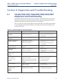
TABLE 6-1. Troubleshooting with Advanced Diagnostics
DIAGNOSTIC MESSAGE
DESCRIPTION OF PROBLEM
REMEDY
“Calibration Warning”
CALIbrAtE
1. Aged glass.
2. Sensor not immersed.
1. Perform buffer calibration.
2. Be sure electrode measuring tip
is in process.
“Cracked glass failure”
Broken or cracked glass.
Replace sensor.
“High reference impede”
rEF fAIL or rEF WjArn
1. Liquid junction coated.
2. Reference Cell gel depleted.
3. Sensor not immersed.
1. Clean sensor; replace if necessary.
2. Replace sensor.
3. Be sure electrode measuring tip
is in process.
“Input voltage high”
“Input voltage low”
pH input shorted or sensor
miswired.
Check wiring. Replace sensor if
necessary.
“Old glass warning”
6LaSS WjArn
1. Glass electrode worn out.
2. Sensor not immersed.
1. Replace sensor.
2. Be sure electrode measuring tip
is inprocess.
“Reference offset err”
(offline only)
Std Err
Reference electrode poisoned.
Replace sensor.
“Ref voltage high”
“Ref voltage low”
1. Reference shorted or sensor miswired.
2. Sensor not immersed
Check wiring and installation.
Replace sensor if necessary.
“Sensor line open”
LInE FAIL
1. Open wire between sensor and analyzer.
2. Interconnecting cable greater than
1000 ft.
1. Check sensor wiring.
2. Relocate analyzer.
“Sensor miswired”
1. Open wire between sensor and analyzer.
2. Bad preamplifier.
1. Check wiring.
2. Replace preamplifier. (Code 02 only)
“Temp error high”
“Temp error low”
1. Open or shorted RTD.
2. Temperature out of range.
1. Replace sensor.
2. Check process temperature.
6LASS fAIL
tEMP HI
tEMP LO
Diagnostics and Troubleshooting
41
Section 6: Diagnostics & Troubleshooting
396P + 396PVP Sensors Instruction Manual
August 2013
6.2
LIQ_MAN_396P_396PVP
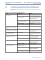
Troubleshooting without Advanced Diagnostics
Table 7-2, below, lists common problems, causes and remedies typically encountered in process
measurement.
TABLE 6-2. Troubleshooting without Advanced Diagnostics
Problem
Probable Cause
Remedy
Meter reads off scale. (Display
reads overrange).
Defective preamplifier
Replace preamplifier (for code 02
sensors). For code 01, replace sensor.
T.C. element shorted
Check T.C. element as instructed
in Section 6.1 and
replace sensor if defective.
Sensor not in process. Sample
stream is low or air bubbles are
present.
Make sure sensor is in process with
sufficient sample stream (refer to
Section 2.0 for installation details).
Open glass electrode
Replace sensor.
Reference element open - no contact
Replace sensor.
Display reads between 3 and 6 pH
regardless of actual pH of solution
or sample.
Electrode cracked
Replace sensor.
Meter or display indication swings
or jumps widely in AUTO T.C. Mode.
T.C. element shorted
Check T.C. element as instructed
in Section 6.1 and replace
sensor if defective.
Span between buffers extremely
short in AUTO T.C. Mode.
T.C. element open
Check T.C. element as instructed
in Section 6.1 and replace sensor
if defective.
Sluggish or slow meter indication
for real changes in pH level.
Electrode coated
Clean sensor as instructed in
Sections 6.2 or Section 6.3.2.
Replace sensor if cracked.
Electrode defective
Replace sensor.
Electrode coated or cracked
Clean Sensor as instructed in
Sections 6.2 or Section 6.3.2
Replace sensor if cracked.
Defective preamplifier
Replace preamplifier.
Aged glass electrode or high
temperature exposure
Replace sensor.
Electrode coated
Clean Sensor as instructed in
Section 6.2 or Section 6.3.2.
Replace sensor if cracked.
Shake the sensor in solution. See
Section 2.0 for mounting guidelines.
Transmitter cannot be standardized.
Transmitter short spans between
two different buffer values.
Air bubbles trapped in sensor end
between glass bulb and sensor body
42
Diagnostics and Troubleshooting
396P + 396PVP Sensors Instruction Manual
Section 6: Diagnostics & Troubleshooting
LIQ_MAN_396P_396PVP
August 2013
TABLE 6-3. Model 396P and 396PVP pH/ORP Replacement Parts and Accessories
PN
DESCRIPTION
11275-01
Sensor Handrail Mounting Assembly
2002011
Flow Cell, CPVC, 1 inch FNPT
23242-02
Mounting Adapter, Insertion, 1 -inch MNPT (304 S.S.) X 1” FNPT (PEEK)
23309-03
Junction Box, for remote preamplifier Code-50
23309-04
Junction Box, for remote preamplifier Code-54
23646-01
Cable, Extension (Prepped) for Models 54, 81, 3081, 4081, and 5081
23555-00
Junction Box with preamplifier, Models 54, 81, 3081, 4081, and 5081 compatible
23557-00
Preamplifier, remote for Junction Box, Models 54, 81, 3081, 4081, and 5081 compatible
22698-00
Preamplifier, Plug-in, Model 1003 compatible (for Code 02-50)
1
22698-02
Preamplifier, Plug-in, Models 1181 and 1050 compatible (for Code 02-50)
1
22698-03
Preamplifier, Plug-in, Models 1054, 1054A, 1054B, 2054, and 2081 compatible (for Code 02-54)
1
22719-02
Junction Box, w/o Preamplifier
33081-00
Adapter Insert, PEEK, 1 X 3/4-inch, for 23242-02
7901631
Shroud, PVC
9200254
Cable, 4 conductor, 22 AWG, shielded pair, for 1054/A/B, 2054, and 1181
9200273
Cable, Extension (Unprepped) for Models 54, 81, 3081, 4081, and 5081
23645-06
15 ft (4.6 m) cable with mating VP connector with BNC on transmitter end
23645-07
15 ft (4.6 m) cable with mating VP connector with bare wires on transmitter end
9210012
Buffer Solution, 4.01pH, 16 oz
4
9210013
Buffer Solution, 6.86pH, 16 oz
4
9210014
Buffer Solution, 9.18pH, 16 oz
4
9322014
Union, KYNAR1
9320057
Union, PVC
9120516
BNC Adapter
915240-04
Tee, Flow-through, 2” PVC, 1” NPT
9550175
O-ring for Mounting Adapter (23242-02)
R508-160Z
ORP Standard Solution, 460mV ±10 at 20°C
23550-00
Junction Box with Extension Board, Models 54, 81, 3081, 4081, and 5081 compatible
661-898695
Cable 5 Conductor (for Model 2700 only)
Diagnostics and Troubleshooting
QUANTITY
43
Section 6: Diagnostics & Troubleshooting
August 2013
44
396P + 396PVP Sensors Instruction Manual
LIQ_MAN_396P_396PVP
Diagnostics and Troubleshooting
396P + 396PVP Sensors Instruction Manual
Section 6: Diagnostics & Troubleshooting
LIQ_MAN_396P_396PVP
August 2013
WARRANTY
Seller warrants that the firmware will execute the programming instructions provided by Seller, and that the Goods manufactured or Services provided by Seller will be free from defects in materials or workmanship under normal use and care until the expiration of the applicable warranty period. Goods are warranted for twelve (12) months from the date of initial installation or eighteen (18) months from the
date of shipment by Seller, whichever period expires first. Consumables, such as glass electrodes, membranes, liquid junctions, electrolyte, o-rings, catalytic beads, etc., and Services are warranted for a period of 90 days from the date of shipment or provision.
Products purchased by Seller from a third party for resale to Buyer ("Resale Products") shall carry only the warranty extended by the original manufacturer. Buyer agrees that Seller has no liability for Resale Products beyond making a reasonable commercial effort to arrange
for procurement and shipping of the Resale Products.
If Buyer discovers any warranty defects and notifies Seller thereof in writing during the applicable warranty period, Seller shall, at its
option, promptly correct any errors that are found by Seller in the firmware or Services, or repair or replace F.O.B. point of manufacture
that portion of the Goods or firmware found by Seller to be defective, or refund the purchase price of the defective portion of the
Goods/Services.
All replacements or repairs necessitated by inadequate maintenance, normal wear and usage, unsuitable power sources, unsuitable environmental conditions, accident, misuse, improper installation, modification, repair, storage or handling, or any other cause not the fault
of Seller are not covered by this limited warranty, and shall be at Buyer's expense. Seller shall not be obligated to pay any costs or charges
incurred by Buyer or any other party except as may be agreed upon in writing in advance by an authorized Seller representative. All costs
of dismantling, reinstallation and freight and the time and expenses of Seller's personnel for site travel and diagnosis under this warranty
clause shall be borne by Buyer unless accepted in writing by Seller.
Goods repaired and parts replaced during the warranty period shall be in warranty for the remainder of the original warranty period or
ninety (90) days, whichever is longer. This limited warranty is the only warranty made by Seller and can be amended only in a writing
signed by an authorized representative of Seller. Except as otherwise expressly provided in the Agreement, THERE ARE NO REPRESENTATIONS OR WARRANTIES OF ANY KIND, EXPRESS OR IMPLIED, AS TO MERCHANTABILITY, FITNESS FOR PARTICULAR PURPOSE, OR ANY
OTHER MATTER WITH RESPECT TO ANY OF THE GOODS OR SERVICES.
RETURN OF MATERIAL
Material returned for repair, whether in or out of warranty, should be shipped prepaid to:
Emerson Process Management
Rosemount Analytical
2400 Barranca Parkway
Irvine, CA 92606
The shipping container should be marked:
Return for Repair
Model _______________________________
The returned material should be accompanied by a letter of transmittal which should include the following information (make a copy of
the "Return of Materials Request" found on the last page of the Manual and provide the following thereon):
1.
2.
3.
4.
5.
Location type of service, and length of time of service of the device.
Description of the faulty operation of the device and the circumstances of the failure.
Name and telephone number of the person to contact if there are questions about the returned material.
Statement as to whether warranty or non-warranty service is requested.
Complete shipping instructions for return of the material.
Adherence to these procedures will expedite handling of the returned material and will prevent unnecessary additional charges for
inspection and testing to determine the problem with the device.
If the material is returned for out-of-warranty repairs, a purchase order for repairs should be enclosed.
Diagnostics and Troubleshooting
45
Section 6: Diagnostics & Troubleshooting
396P + 396PVP Sensors Instruction Manual
August 2013
LIQ_MAN_396P_396PVP
This page left blank intentionally
46
396P + 396PVP Sensors Instruction Manual
Section 7: Return of Material
LIQ_MAN_396P_396PVP
August 2013
Section 7: Return of Material
7.1
General
To expedite the repair and return of instruments, proper communication between the
customer and the factory is important. Before returning a product for repair, call 1-949-7578500 for a Return Materials Authorization (RMA) number.
7.2
Warranty Repair
The following is the procedure for returning instruments still under warranty:
1. Call Rosemount Analytical for authorization.
2. To verify warranty, supply the factory sales order number or the original purchase order
number. In the case of individual parts or sub-assemblies, the serial number on the unit
must be supplied.
3. Carefully package the materials and enclose your “Letter of Transmittal” (see Warranty). If
possible, pack the materials in the same manner as they were received.
4. Send the package prepaid to:
Rosemount Analytical
2400 Barranca Parkway
Irvine, CA 92606
Attn: Factory Repair
RMA No. ____________
Mark the package: Returned for Repair
Model No. ____
7.3
Non-Warranty Repair
The following is the procedure for returning for repair instruments that are no longer
under warranty:
1. Call Rosemount Analytical for authorization.
2. Supply the purchase order number, and make sure to provide the name and telephone
number of the individual to be contacted should additional information be needed.
3. Do Steps 3 and 4 of Section 9.2.
NOTE: Consult the factory for additional information regarding service or repair.
Return of Material
47
LIQ_MAN_396P_396PVP
Rev. B
August 2013
facebook.com/EmersonRosemountAnalytical
8
AnalyticExpert.com
Credit Cards for U.S. Purchases Only.
twitter.com/RAIhome
youtube.com/user/RosemountAnalytical
Emerson Process Management
©2013 Rosemount Analytical, Inc. All rights reserved.
2400 Barranca Parkway
Irvine, CA 92606 USA
Tel: (949) 757-8500
Fax: (949) 474-7250
The Emerson logo is a trademark and service mark of Emerson Electric Co. Brand name is a mark
of one of the Emerson Process Management family of companies. All other marks are the property
of their respective owners.
rosemountanalytical.com
© Rosemount Analytical Inc. 2013
The contents of this publication are presented for information purposes only, and while effort has
been made to ensure their accuracy, they are not to be construed as warranties or guarantees,
express or implied, regarding the products or services described herein or their use or applicability.
All sales are governed by our terms and conditions, which are available on request. We reserve the
right to modify or improve the designs or specifications of our products at any time without notice.