1
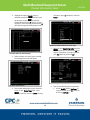
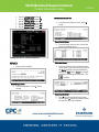
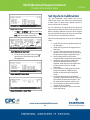
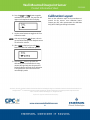
Wall-Mounted Dewpoint Sensor 210-2002 Product Information Sheet this transformer devices.) Overview The 210-2002 is a Vaporstat™ wall-mounted dewpoint sensor. The sensor is designed for measuring indoor or outside dewpoint or absolute humidity level. to power additional 5. Locate the input dip switch for the sensor point, and set to the OFF position (LEFT for MultiFlex, DOWN for 16AI). Refer to the input board’s user manual for locations of the input dip switches. Sensor Wiring Controller Setup 1. For wiring the dewpoint sensor to a CPC input board, use Belden #8761 shielded twoconductor cable or equivalent. NOTE: DO NOT set this sensor up with a sensor type of “Dewpoint”; that setting is only for CPC Dewpoint Probes (P/N 203-1902). This dewpoint sensor MUST be set up as a linear sensor type. 2. Connect the BLACK and WHITE wires to the screw terminals on the sensor’s connector as shown in Figure 1 (connect BLACK to Signal Ground and WHITE to 0-5V Output). Clip the SHIELD wire. E2/Einstein 1. After logging into the controller, press 6 + to open the Input Status screen or press the I key, (System Configuration), (Input Summary). (If using an Einstein, press F8(ACTIONS) from the Home screen. Press Y (System Setup). Press 6 (Input and Output Point Setup). Press 1 (Input Summary) to open the Input Summary screen.) Figure 1 - Sensor and Input Board Wiring 3. Connect the SHIELD and BLACK wires to the 0V terminal of the input board. Connect the WHITE wire to the SIG terminal of the input board. 4. Connect 24VAC (a separate 120VAC/24VAC transformer must be used P/N 640-0039) to the power terminal on the dewpoint sensor back plate using the BLACK and WHITE wires. (This 24VAC transformer must only be used to power this dewpoint sensor. Do not use Input Status Screen 47 Wall-Mounted Dewpoint Sensor Product Information Sheet 2. Highlight the input-point the sensor is 210-2002 an Einstein, press F7 (LOOK UP) and set to Linear.) attached to and press (SETUP) to set up the input, or press to open the Actions Menu and select 5 (Setup). (If using an Einstein, select an input point and press F7 (SETUP IN) to open the Analog Input screen.) Option List Selection Menu For Sensor Type 5. Move cursor to Select Eng. Units and press (LOOK UP). Set this field to DF (for Degrees Fahrenheit). (If using an Einstein, press F7 (LOOK UP) and set to DF.) E2 Actions Menu for Selected Input 3. Select Analog to set up the input as analog. The Analog Input screen will display: Set Sensor Type to Linear Set Sensor Type to Linear 6. Then set the following sensor properties: • Set the Modify field to: EndPoint. (If using an Einstein, press F7 (LOOK UP) and set to EndPoint.) 4. Once on the Analog Input screen, move the cursor to the Sensor Type field, press (LOOK UP), and set to Linear. (If using 48 Wall-Mounted Dewpoint Sensor Product Information Sheet • • • • • • Set the Low End Point field to 0. Set the HighEnd Point field to 5.0. Set the Low Eng. Units field to 0. Set the High Eng. Units field to 80. Set the Low End Limit field to -0.5. Set the HighEnd Limit field to 6.5. 210-2002 REFLECS Main Menu Screen 3. From the Sensor Control screen, select 2 Setup. Sensor Control Screen 4. From the Select Sensor screen, choose the sensor you wish to set up: Analog Input Screen - Set Sensor Properties Select Item Screen REFLECS 5. Once you select a sensor, the Sensor Setup screen opens. Enter a name for the sensor in the Name field (for example, DEWPOINT) and set the Type field to Linear by using the scroll keys or pressing the red button + the 1. Log in to the controller. (L) button. REFLECS Login Screen 2. From the Main Menu, select 4 -Sensor Control. Sensor Control Screen 6. Press 0 to go back to the Sensor Control screen. Select 3 -Setpoints and then choose the sensor to set Gain and Offset. 49 Wall-Mounted Dewpoint Sensor Product Information Sheet 210-2002 Set Up Zero Calibration The Zero Calibration mode allows the user to calibrate the sensor to a verified zero concentration of water vapor. For best results, allow the sensor to warm up for at least 10 minutes. For zero calibration, all tubing should be connected between the gas bottle and the sensor inlet flow port. Before initiating calibration using the sensor keypad, the gas should be flowed to the sensor at a rate of 80100 cc\minute for a period of five minutes. Sensor Control Screen 7. Set Gain to 16, Offset to 0 (the default) and enter degrees fahrenheit units into the Eng. Unit field (for example, type DEGF). Observe the following steps to set up Zero Calibration mode. 1. Attach the short hose to the bottom port on the flowmeter. 2. Attach the long hose to the top port on the flowmeter. 3. To ensure the meter is kept in the vertical position, secure the flowmeter to the side of the gas bottle using the supplied tie wrap. 4. Remove the protective cap from the nitrogen bottle and attach the gas regulator. 5. Attach the open end of the bottom hose (located on the flowmeter) to the gas regulator. Slide the hose far enough on the gas port to ensure a secure, airtight connection. 6. Insert the male luer fitting (located on the longer hose) into the calibration port, located on the bottom of the dewpoint sensor. 7. Verify that all components are installed correctly and initiate the calibration process by turning the knob on the regulator. Turn the knob until the indicator reaches 7 psi. 8. Turn the flowmeter knob until the floater reaches 80-100 cc/minute. 9. Allow the gas to flow for at least 5 minutes before proceeding. Sensor Setpoints for Linear Input 8. To check the sensor input value, press 0 to go back to the Sensor Control screen and select 1 -Status. Sensor Setpoints for Linear Input Sensor Status Screen – Sensor Value 50 Wall-Mounted Dewpoint Sensor Product Information Sheet 10. Press the Clear and Enter buttons together and hold for five seconds. The word CAL will appear in the topline of the LCD display: 210-2002 Calibration Layout Refer to the calibration topic of the manufacturer’s manual for the sensor’s zero calibration layout. Contact your CPC sales representative for calibration kit (P/N 210-2005) purchasing information. 11. Use the arrow buttons to toggle to the Zero Calibration mode. NOTE: Prior to pressing the Enter button, the zero gas should be flowing to the dewpoint sensor for atleast five minutes. 12. When ZERO is displayed, press the Enter button to initiate the calibration process. 13. Once the Enter button is pressed, the calibration process will take five to seven minutes during which time the green LED below the display will flash. Once calibration is completed, the sensor will revert to its normal display mode. EmersonTM, Emerson. Consider It SolvedTM and Emerson Climate TechnologiesTM logos are trademarks and service marks of Emerson Electric Co Intelligent StoreTM is a trademark of Emerson Climate Technologies. All other trademarks are the property of their respective owners. © 2011 Emerson Climate Technologies, Inc. All rights reserved. Vaporstat™ is a registered trademark of Telaire company. 51