1
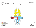
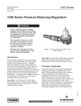
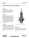
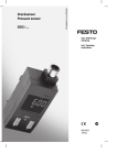
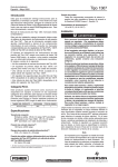
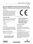
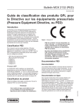
Types 1301F and 1301G
Instruction Manual
Form 1111
December 2013
1301 Series High-Pressure Regulators
!
WARNING
Failure to follow these instructions or
to properly install and maintain this
equipment could result in an explosion,
fire and/or chemical contamination
causing property damage and personal
injury or death.
Fisher® regulators must be installed,
operated, and maintained in accordance
with federal, state and local codes, rules
and regulations, and Fisher instructions.
If the regulator vents gas or a leak
develops in the system, service to the unit
may be required. Failure to correct trouble
could result in a hazardous condition.
Installation, operation, and maintenance
procedures performed by unqualified
personnel may result in improper
adjustment and unsafe operation. Either
condition may result in equipment
damage or personal injury. Use qualified
personnel when installing, operating,
and maintaining the 1301 Series highpressure regulator.
Introduction
P1025
Figure 1. Type 1301F High-Pressure Regulator
supply pressure in pilot-operated regulators or as
loading pressure in pressure-loaded regulators.
Scope of the Manual
This Instruction Manual provides instructions for the
installation, adjustment, maintenance, and parts ordering
of the Types 1301F and 1301G high-pressure regulators.
Product Description
The Type 1301F can handle outlet pressures from
10 to 225 psig / 0.69 to 15.5 bar in three ranges and
the Type 1301G can handle outlet pressures from
200 to 500 psig / 13.8 to 34.5 bar in one range.
D100341X012
Types 1301F and 1301G regulators are direct-operated,
high-pressure regulators, which can be used where
high-pressure gas must be reduced for use as pilot
Types 1301F and 1301G regulators can also be used
in many other applications due to their rugged design
as high-pressure reducing regulators for various fluids
such as air, gas, water, and other liquids.
www.fisherregulators.com
Types 1301F and 1301G
Specifications
Specifications section lists the specifications for Types 1301F and 1301G high-pressure regulators. The maximum
outlet pressure for a given regulator as it comes from the factory is stamped on the regulator nameplate.
Available Configurations
Type 1301F: Direct-operated, high-pressure reducing
regulator for inlet pressures to 6000 psig / 414 bar
and outlet pressure ranges from 10 to 225 psig /
0.69 to 15.5 bar in three ranges
Type 1301G: Direct-operated, high-pressure
reducing regulator for inlet pressures to 6000 psig /
414 bar and an outlet pressure range of
200 to 500 psig / 13.8 to 34.5 bar
IEC Sizing Coefficients
XT: 0.938
FD: 0.50
FL: 0.85
Recovery Coefficient
Km: 0.72
Material Temperature Capabilities(1)
Nylon (PA) Valve Disk and
Neoprene (CR) Gaskets:
-20 to 180°F / -29 to 82°C
Body Size and End Connection Style
1/4 NPT (one inlet and two or three outlet
connections), CL300 RF, CL600 RF, and CL1500 RF;
or PN 25 RF (all flanges are 125 RMS)
Maximum Allowable Inlet Pressure(1)
Brass Body:
Air and Gas:
6000 psig / 414 bar at or below 200°F / 93°C and
1000 psig / 69.0 bar above 200°F / 93°C
Liquid:
Polytetrafluoroethylene (PTFE) Disk:
1000 psig / 69.0 bar
Nylon (PA) Disk:
Water: 1000 psig / 69.0 bar
Other Liquids: 2000 psig / 138 bar
Stainless Body:
Air and Gas: 6000 psig / 414 bar
Liquid:
Polytetrafluoroethylene (PTFE) Disk:
1000 psig / 69.0 bar
Nylon (PA) Disk:
Water: 1000 psig / 69.0 bar
Other Liquids: 2000 psig / 138 bar
Outlet Pressure Ranges
See Table 1
Maximum Emergency Outlet Pressure(1)
Type 1301F: 250 psig / 17.2 bar
Type 1301G: 550 psig / 37.9 bar
Wide-Open Flow Coefficients for Relief Valve Sizing
Cg: 5.0
Cv: 0.13
C1: 38.5
PTFE Valve Disk and Fluorocarbon (FKM)
Gaskets: -20 to 400°F / -29 to 204°C(2)
PTFE Valve Disk and Ethylenepropylene (EPDM)
Gaskets: -40 to 300°F / -40 to 149°C
Low Temperature Service
Service to -65°F / -54°C is available with low
temperature bolting and special low temperature
Nitrile (NBR) O-rings to replace the gaskets.
Service to -80°F / -62°C is available with low
temperature bolting and special low temperature
Fluorosilicone (FVQM) O-rings to replace
the gaskets.
Pressure Registration
Internal
Orifice Size
5/64 inch / 2.0 mm
Spring Case Vents
Type 1301F Brass Spring Case:
Four 5/32-inch / 4.0 mm holes
Type 1301F Stainless Steel Spring Case:
One 1/4 NPT connection
Type 1301G Spring Case:
One 1/8 NPT connection with screen
Approximate Weight
8 pounds / 4 kg
1. The pressure/temperature limits in this Instruction Manual and any applicable standard or code limitation should not be exceeded.
2. Fluorocarbon (FKM) is limited to 180°F / 82°C hot water.
2
Types 1301FType
and1301F
1301G
CONTROL SPRING
DIAPHRAGM
DISK HOLDER
M1015
VALVE DISK
SPARE DISK
INLET PRESSURE
OUTLET PRESSURE
ATMOSPHERIC PRESSURE
VALVE SPRING
BOTTOM CAP
M1015
Inlet pressure
Outlet pressure
atmospheric pressure
Figure 2. Type 1301F Operational Schematic
Table 1. Outlet Pressure Ranges
TYPE
1301F
1301G
OUTLET PRESSURE
RANGES(1)
SPRING COLOR
SPRING PART NUMBER
SPRING WIRE DIAMETER
psig
bar
Inch
mm
10 to 75
0.69 to 5.2
Blue
1D387227022
0.200
5.08
50 to 150
3.4 to 10.3
Silver
1B788527022
0.225
5.72
100 to 225
6.9 to 15.5
Red
1D465127142
0.243
6.17
200 to 500
13.8 to 34.5
Silver
1K156027142
0.331
8.41
SPRING FREE LENGTH
Inch
mm
1.69
42.9
0.88
22.4
1. All springs can be backed off to 0 psig / 0 bar.
Principle of Operation
The 1301 Series regulators are direct-operated.
Downstream pressure is registered internally through
the body to the underside of the diaphragm. When
downstream pressure is at or above set pressure,
the disk is held against the orifice and there is no
flow through the regulator. When demand increases,
downstream pressure decreases slightly allowing the
regulator spring to extend, moving the yoke and disk
assembly down and away from the orifice. This allows
flow through the body to the downstream system. As
the downstream pressure reaches its setpoint, it starts
to overcome the spring force, which is sensed by the
diaphragm, moving the yoke and disk assembly up near
its orifice, restricting flow across the regulator.
3
Types 1301F and 1301G
Installation
!
Warning
Overpressuring a regulator or
associated equipment may cause
leakage, part damage, or personal injury
due to bursting of pressure containing
parts or explosion of accumulated gas.
Do not install a regulator where service
conditions can exceed the specifications
listed on the Specifications section, or
any applicable local, state or federal
codes and regulations.
Use qualified personnel when installing, operating, and
maintaining these regulators. Make sure that there
is no damage or foreign material in the regulator and
that all tubing and piping are clean and unobstructed.
The regulator may be installed in any position. Apply
pipe compound to the pipeline threads. Connect inlet
piping or tubing to the 1/4 NPT connection marked
“In” and outlet piping or tubing to one of the 1/4 NPT
connections marked “Out”. Install a pressure gauge or
pipe plug in the unused outlet connections.
If continuous operation of the system is required
during inspection or maintenance, install a three-valve
bypass around the regulator.
!
Warning
A regulator may vent some gas to
the atmosphere. In hazardous gas
service, vented gas may accumulate,
causing personal injury or equipment
damage due to fire or explosion. Vent
a regulator in hazardous gas service to
a remote, safe location.
The optional stainless steel spring case of the
Type 1301F regulator has one 1/4 NPT internal
connection. The Type 1301G regulator spring case
has one 1/8 NPT internal connection with a screen. To
remotely vent the spring case, remove the screen, if
present, and connect 1/4 or 1/8 NPT piping or tubing
to the spring case connection. The piping or tubing
should vent the spring case to a safe location, have as
few bends as possible, and have a screened vent on its
exhaust end.
Each regulator is factory-set for the pressure setting
specified on the order. If no setting is specified, outlet
4
pressure is factory-set at the midpoint of the regulator
spring range. If pressure adjustment is necessary, refer
to the Startup section. In all cases, check the spring
setting to make sure it is correct for the application.
Overpressure Protection
The 1301 Series regulators have an outlet pressure
rating lower than their inlet pressure rating. If actual
inlet pressure can exceed the outlet pressure rating,
outlet overpressure protection is necessary. However,
overpressuring any portion of the regulators beyond
the limits in Specifications section may cause leakage,
damage to regulator parts, or personal injury due to
bursting of pressure-containing parts.
Some type of external overpressure protection should be
provided if inlet pressure will be high enough to damage
downstream equipment. Common methods of external
overpressure protection include relief valves, monitoring
regulators, shutoff devices, and series regulation.
If the regulator is exposed to an overpressure
condition, it should be inspected for any damage that
may have occurred. Regulator operation below these
limits does not preclude the possibility of damage from
external sources or from debris in the pipeline.
Startup
With installation completed and downstream
equipment adjusted, slowly open the upstream and
downstream block valves while using pressure gauges
to monitor pressure.
If adjustment is necessary, loosen the locknut
(key 18, Figures 3 and 4), and turn the adjusting
screw (key 15, Figures 3 and 4) clockwise to
increase the set pressure or counterclockwise to
decrease the set pressure. Monitor pressure with
gauges during adjustment. When adjustment is
complete, tighten the locknut. If the desired outlet
pressure is not within the range of the regulator
spring, install a spring with a desired range
according to the Maintenance section.
Shutdown
First, close the upstream shutoff valve, and then,
close the downstream shutoff valve. Next, open
the vent valve between the regulator and the
downstream shutoff valve and open the vent valve
between the regulator and the upstream shutoff
valve. If vent valves are not installed, safely bleed
off both inlet and outlet pressures and check that
the regulator contains no pressure.
Types 1301F and 1301G
Maintenance
Regulator parts are subject to normal wear and must be
inspected and replaced as necessary. The frequency
of inspection and parts replacement depends on the
severity of service conditions and the requirements of
local, state, and federal rules and regulations.
Instructions are given below for disassembly and
assembly of parts.
!
Warning
To avoid personal injury or equipment
damage from sudden release of pressure
or explosion of accumulated gas, do not
attempt any maintenance or disassembly
without first isolating the regulator from
system pressure and relieving all internal
pressure from the regulator.
9. Remove the screws (key 17) from the yoke, and
take the lower and upper halves of the yoke out
of the body. The yoke halves are a matched set
and need to be kept together.
10.Unscrew the orifice (key 5). Examine seating
edge of orifice. Replace with a new part if
worn or nicked.
Assembly
This procedure assumes that the regulator was
completely disassembled. If not, start these
instructions at the appropriate step. Key numbers
used are shown in Figure 3 for the Type 1301F
regulator and in Figure 4 for the Type 1301G regulator
unless otherwise indicated.
1. Screw the orifice (key 5) into the regulator.
Disassembly
2. Insert both halves of the yoke (key 4) into the
regulator, and fasten them together with the
screws (key 17). The yoke halves are a matched
set and need to be kept together.
The following procedure describes how to completely
disassemble the regulator. When part replacement
or inspection is required, complete only those steps
necessary to accomplish the job. Key numbers
referenced are shown in Figure 3 for the Type 1301F
regulator and in Figure 4 for the Type 1301G regulator
unless otherwise indicated.
3. The valve disk assembly (key 6) has two valve
disks, one on each end. Inspect both valve disks,
and select the one to be used. Thread the valve
disk assembly into the yoke so that the disk to be
used is positioned against the orifice. Thread the
valve disk collar (key 22) onto the exposed end of
the valve disk assembly.
1. Loosen the locknut (key 18).
2. Turn the adjusting screw (key 15)
counterclockwise to remove spring compression.
3. Remove the bottom cap (key 3), bottom cap
O-ring (key 14), and spring (key 10).
4. Unthread the valve disk assembly (key 6) from
the yoke (key 4).
5. Remove the valve disk collar (key 22) from the
valve disk assembly.
6. Remove the spring case cap screws (key 16),
and separate the spring case (key 2) from the
body (key 1).
7. Remove the upper spring seat and spring
(keys 9 and 11).
8. Refer to Figure 5. Unscrew the diaphragm
locknut (key 19), and remove the diaphragm
plate (key 8), the two diaphragms (key 7), and the
diaphragm plate gasket (key 13).
4. Place the bottom cap O-ring (key 14) on the
bottom cap (key 3). Place the spring (key 10) in
the bottom cap, and thread it into the regulator.
5. Put the body gasket (key 12) on the regulator
body (key 1).
6. Refer to Figure 5. Place the diaphragm plate
gasket (key 13), two diaphragms (key 7), and
the diaphragm plate (key 8) on the yoke (key 4).
Make sure the diaphragm convolutions are toward
the spring, and secure the parts by threading the
diaphragm locknut (key 19) onto the yoke.
7. Place the regulator spring (key 11) and upper
spring seat (key 9) on the diaphragm plate.
8. Position the spring case (key 2) over the spring and
on the regulator body. Orient the spring case vent or
vents as necessary. Insert the cap screws (key 16),
and tighten them only finger-tight.
9. Thread the adjusting screw and locknut (keys 15
and 18) into the spring case just far enough to
slightly compress the spring. Securely tighten the
cap screws (key 16), and refer to the Startup section
for adjustment procedures.
5
Types 1301F and 1301G
2
9
11
8
19
7
16
17
13
4
14
5
US
12
A
AX
M
1
40
T
LE I
IN
X. PS
MA 000
6
18
S
FIS H E R
15
20
.O
UT
L
P S ET
I
NOTE: OPTIONAL THIRD OUTLET
3
6
10
22
CD3923_F
Figure 3. Type 1301F High-Pressure Regulator Assembly
15
19
2
18
11
9
19
8
7
21
1
12
13
17
17
14
5
4
8
7
16
4
3
13
6
22
10
BP6341-A
CN7095_C
Figure 4. Type 1301G High-Pressure Regulator Assembly
6
Figure 5. Exploded View of The Diaphragm Head
Assembly and Yoke
Types 1301F and 1301G
Parts Ordering
Key Description
When corresponding with your local Sales Office about
this regulator, include the type number and all other
pertinent information stamped on the bottom cap and
on the nameplate. Specify the complete 11-character
part number from the following parts list when ordering
replacement parts.
Parts List
Note
Parts marked NACE in this parts list
are intended for corrosion-resistant
service as detailed in the NACE
International Standards MR0175/
ISO 15156 and/or MR0103.
Key Description
Part Number
Parts Kits (Includes keys 5, 6, 7, 12, 13, and 14)
Stainless steel kits include Fluorocarbon (FKM)
gaskets. Brass kits include Neoprene (CR) gaskets.
Brass
With Nylon (PA) Disk
Stainless steel
With Nylon (PA) Disk
Brass
With PTFE Disk
Stainless steel
With PTFE Disk
1 Body
1/4 NPT Connection
Brass (2 outlet port)
Brass (3 outlet port)
CF8M Stainless steel (2 outlet port)
CF8M Stainless steel (3 outlet port)
1/4 x 1/2-inch Flanged Connection
CF8M Stainless steel
CL300 RF
CL600 RF
CL1500 RF
PN 25
1/4 x 1-inch Flanged Connection
CF8M Stainless steel
CL300 RF
CL600 RF
CL1500 RF
PN 25
Body (Cold Temperature)
1/4 NPT Connection
CF8M Stainless steel (2 outlet port)
CF8M Stainless steel (3 outlet port)
NPS 1/4, NPT Connection
2
Spring Case
Type 1301F
Brass
Standard or with T-Handle
CF8M Stainless steel
With 1/4 NPT vent connection
R1301FX0012
R1301FX0022
R1301FX0032
R1301FX0042
39A1342X012
ERAA00584A0
32B4291X022
ERAA00603A0
14B1420X012
14B2059X012
14B3375X012
14B3377X012
14B3376X012
14B1386X012
14B3370X012
14B3377X022
34B0527X012
ERAA00604A0
1D383113012
Part Number
2
Spring Case (continued)
Type 1301G
1/8 NPT vent connection
Standard or with T-Handle
Brass 2P195713022
316 Stainless steel 21A6377X012
3
Bottom Cap
Brass 1D468513012
304 Stainless steel 1J919635072
316 Stainless steel (NACE)
1J9196X0032
4
Yoke
Brass 1D383313012
316 Stainless steel (NACE)
1J925936042
5* Orifice
303 Stainless steel
1D386535032
316 Stainless steel (NACE)
1D3865X0032
6* Valve Disk Assembly
Brass/Nylon (PA)
1D4684000A2
Brass/PTFE 1D4684X0012
303 Stainless steel/Nylon (PA)
1D4684000C2
303 Stainless steel/PTFE 1D4684000B2
306 Stainless steel/PTFE (NACE)
1D4684X0082
7* Diaphragm (2 required)
302 Stainless steel 1D387036012
K500 Monel® (NACE)
1D3870X0012
8
Diaphragm Plate, Zinc-plated steel
Type 1301F 1D387325072
Type 1301G 1K155725072
9
Upper Spring Seat, Steel
Type 1301F 1B798525062
Type 1301G 1K155828982
10 Valve Spring
302 Stainless steel
1D387137022
Inconel® X750 (NACE)
15A3522X012
11 Spring, Zinc-plated steel
Type 1301F
0 to 75 psig / 0 to 5.2 bar, Blue 1D387227022
0 to 150 psig / 0 to 10.3 bar, Silver
1B788527022
0 to 225 psig / 0 to 15.5 bar, Red 1D465127142
Type 1301G
200 to 500 psig / 13.8 to 34.5 bar, Silver
1K156027142
12* Body Gasket
Neoprene (CR)
1D372903012
Fluorocarbon (FKM)
1D372904122
13* Diaphragm Plate Gasket
Neoprene (CR)
1D373003012
Fluorocarbon (FKM)
1D373004122
14* Bottom Cap O-ring
Fluorocarbon (FKM)
1J926806382
EPDM
1J9268X0022
Nitrile (NBR) -65F
1J9268X0012
Fluorosilicone (FVQM) -80F
ERAA03306A0
15 Adjusting Screw
Type 1301F
Steel (standard)
1E639928992
Handwheel, 416 Stainless steel
1N411435132
T-handle, Steel
1F2236000A2
Type 1301G
Zinc-plated steel (standard)1K140624092
T-handle, Steel
19A8060X012
16 Spring Case Cap Screw (6 required)
Zinc-plated steel
1E8220X0012
Stainless steel
1E8220X0212
Stainless steel
(For Type 1301G Cold Temperature)
1E8220X0022
22B0753X012
*Recommended spare part.
Monel® and Inconel® are trademarks of Special Metals Corporation.
7
Types 1301F and 1301G
Parts List (continued)
Key Description
17 Machine Screw (2 required)
Steel, for brass yoke 302 Stainless steel, for Stainless steel yoke 18 Locknut
Type 1301F
Brass (for standard spring case)
Steel (for Stainless steel spring case)
Type 1301G
Zinc-plated steel
19 Diaphragm Locknut, Aluminum
21 Top Connector, 316 Stainless steel
Use with Stainless steel yoke only 22 Valve Disk Collar
304 Stainless steel 316 Stainless steel (NACE)
24 Handwheel (Not shown)
Type 1301F 26 Vent Screen (Not shown)
Type 1301F, 18-8 Stainless steel
Type 1301G, 304 Stainless steel
27 Mounting Post (3 required) (Not shown)
Type 1301F T-handle panel mounting only,
316 Stainless steel
Type 1301G panel mounting only, Steel
28 Mounting Screw, Brass (3 required)
Use with key 27 (Not shown) Part Number
1H526928982
1J926938992
1A518014012
1A352224122
1A354024122
1A309324122
1J926035072
1D468635032
1D4686X0012
1L217544992
0L078343062
0W086343062
1F2449X0022
1L2629X0012
0V070414012
Key Description
Part Number
29 Screw, Steel (Not shown)
Type 1301F with handwheel and steel
spring case only
30 Washer, Steel (Not shown)
Type 1301F with handwheel and steel
spring case only
32 Mounting Bracket (Not shown)
Yoke mounted
Casing mounted
33 Bracket Cap Screw (2 required)
Use with key 32 (Not shown)
34 Bracket Mounting Washer
Use with key 32 (Not shown)
35 NACE Tag
Use with NACE unit (Not shown)
36 Tag Wire
Use with key 35 (Not shown)
38* Body O-ring (Not shown)
Use with -65°F / -54°C Cold Service Unit
Use with -80°F / -62°C Cold Service Unit
39* Top Connector O-ring (Not shown)
Use with -65°F / -54°C Cold Service Unit
Use with -80°F / -62°C Cold Service Unit
40 Pipe Plug (Not shown)
Brass
Stainless steel
1E985428982
1L449428982
22A6305X012
1U9284X0012
1C631224052
T12861T0012
--------------------1V3252X0012
ERAA03305A0
14B8848X012
ERAA03307A0
1C333528992
1C3335X0012
*Recommended spare part.
Industrial Regulators
Natural Gas Technologies
TESCOM
Emerson Process Management
Regulator Technologies, Inc.
Emerson Process Management
Regulator Technologies, Inc.
Emerson Process Management
Tescom Corporation
USA - Headquarters
McKinney, Texas 75070 USA
Tel: +1 800 558 5853
Outside U.S. +1 972 548 3574
USA - Headquarters
McKinney, Texas 75070 USA
Tel: +1 800 558 5853
Outside U.S. +1 972 548 3574
USA - Headquarters
Elk River, Minnesota 55330-2445, USA
Tels: +1 763 241 3238
+1 800 447 1250
Asia-Pacific
Shanghai 201206, China
Tel: +86 21 2892 9000
Asia-Pacific
Singapore 128461, Singapore
Tel: +65 6770 8337
Europe
Selmsdorf 23923, Germany
Tel: +49 38823 31 287
Europe
Bologna 40013, Italy
Tel: +39 051 419 0611
Europe
Bologna 40013, Italy
Tel: +39 051 419 0611
Chartres 28008, France
Tel: +33 2 37 33 47 00
Asia-Pacific
Shanghai 201206, China
Tel: +86 21 2892 9499
Middle East and Africa
Dubai, United Arab Emirates
Tel: +011 971 4811 8100
Middle East and Africa
Dubai, United Arab Emirates
Tel: +011 971 4811 8100
For further information visit www.fisherregulators.com
The Emerson logo is a trademark and service mark of Emerson Electric Co. All other marks are the property of their prospective owners. Fisher is a mark owned by Fisher Controls International LLC,
a business of Emerson Process Management.
The contents of this publication are presented for informational purposes only, and while every effort has been made to ensure their accuracy, they are not to be construed as warranties or
guarantees, express or implied, regarding the products or services described herein or their use or applicability. We reserve the right to modify or improve the designs or specifications of such
products at any time without notice.
Emerson Process Management Regulator Technologies, Inc. does not assume responsibility for the selection, use or maintenance of any product. Responsibility for proper selection, use and
maintenance of any Emerson Process Management Regulator Technologies, Inc. product remains solely with the purchaser.
©Emerson Process Management Regulator Technologies, Inc., 1975, 2013; All Rights Reserved