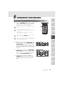
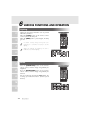
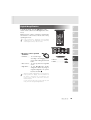
1
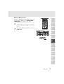
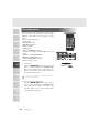
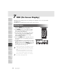
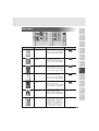
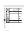
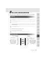
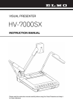
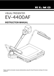
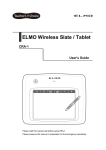
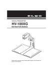
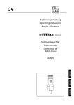
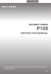
CEILING PRESENTER
HV-C1000XG
INSTRUCTION MANUAL
Please read this instruction manual carefully before using this product and keep it for future reference.
IMPORTANT SAFEGUARDS
■ Read Instructions – All the safety
and operating instructions should be
read before the appliance is
operated.
■ Retain Instructions – The safety and
operating instructions should be
retained for future reference.
■ Heed Warnings – All warnings on
the product and in the operating
instructions should be adhered to.
■ Follow Instructions – All operating
and use instructions should be
followed.
■ Cleaning – Unplug this product
from the wall outlet before cleaning.
Do not use liquid cleaners or aerosol
cleaners. Use a damp cloth for
cleaning.
■ Attachments – Do not use
attachments not recommended by the
product manufacturer as they may
cause hazards.
■ Water and Moisture – Do not use
this product near water - for example,
near a bath tub, wash bowl, kitchen
sink, or laundry tub, in a wet
basement, or near a swimming pool,
and the like.
■ Accessories – Do not place this
product on an unstable cart, stand,
tripod, bracket, or table. The product
may fall, causing serious injury to a
child or adult, and serious damage to
the product. Use only with a cart,
stand, tripod, bracket, or table
recommended by the manufacturer, or
sold with the product. Any mounting
of the product should follow the
1
manufacturer's instructions, and
should use a mounting accessory
recommended by the manufacturer.
■ Ventilation – Slots and openings in
the cabinet are provided for
ventilation and to ensure reliable
operation of the product and to
protect it from overheating, and these
openings must not be blocked or
covered. The openings should never
be blocked by placing the product on
a bed, sofa, rug, or other similar
surface. This product should not be
placed in a built-in installation such as
a bookcase or rack unless proper
ventilation is provided or the
manufacturer's instructions have been
adhered to.
■ Power Sources – This product
should be operated only from the type
of power source indicated on the
marking label. If you are not sure of
the type of power supply to your
home consult your appliance dealer
or local power company. For products
intended to operate from battery
power, or other sources, refer to the
operating instructions.
■ Grounding or Polarization – This
product may be equipped with either
a polarized 2-wire AC line plug (a
plug having one blade wider than the
other) or a 3-wire grounding type
plug, a plug having a third
(grounding) pin. The 2-wire polarized
plug will fit into the power outlet only
one way. This is a safety feature. If
you are unable to insert the plug fully
into the outlet, try reversing the plug.
If the plug still fails to fit, contact your
electrician to replace your obsolete
outlet. Do not defeat the safety
purpose of the polarized plug. The 3wire grounding type plug will fit into
a grounding type power outlet. This is
a safety feature. If you are unable to
insert the plug into the outlet, contact
your electrician to replace your
obsolete outlet. Do not defeat the
safety purpose of the grounding type
plug.
■ Power-Cord Protection – Powersupply cords should be routed so that
they are not likely to be walked on or
pinched by items placed upon or
against them, paying particular
attention to cords at plugs,
convenience receptacles, and the
point where they exit from the
product.
■ Lightning – For added protection
for this product during a lightning
storm, or when it is left unattended
and unused for long periods of time,
unplug it from the wall outlet and
disconnect the antenna or cable
system. This will prevent damage to
the product due to lightning and
power-line surges.
■ Overloading – Do not overload
wall outlets, extension cords, or
integral convenience receptacles as
this can result in a risk of fire or
electric shock.
■ A product and
cart combination
should be moved
with care. Quick
stops, excessive
force, and uneven
surfaces may cause the product and
cart combination to overturn.
■ Object and Liquid Entry – Never
push objects of any kind into this
product through openings as they
may touch dangerous voltage points
or short-out parts that could result in a
fire or electric shock. Never spill
liquid of any kind on the product.
■ Servicing – Do not attempt to
service this product yourself as
opening or removing covers may
expose you to dangerous voltage or
other hazards. Refer all servicing to
qualified service personnel.
WARNING : Handling the
cord on this product or
cords associated with
accessories sold with this
product, will expose you to
lead, a chemical known to
the State of California to
cause birth defects or
other reproductive harm.
Wash hands after
handling.
2
■ Damage Requiring Service –
Unplug this product from the wall
outlet and refer servicing to qualified
service personnel under the following
conditions:
● When the power-supply cord or
plug is damaged.
● If liquid has been spilled, or
objects have fallen into the
product.
● If the product has been exposed
to rain or water.
● If the product does not operate
normally by following the
operating instructions. Adjust
only those controls that are
covered by the operating
instructions as an improper
adjustment of other controls
may result in damage and will
often require extensive work by
a qualified technician to restore
the product to its normal
operation.
● If the product has been dropped
or damaged in any way.
● When the product exhibits a
distinct change in performance this indicates a need for service.
■ Replacement Parts – When
replacement parts are required, be
sure the service technician has used
replacement parts specified by the
manufacturer or have the same
characteristics as the original part.
Unauthorized substitutions may result
in fire, electric shock or other
hazards.
3
■ Safety Check – Upon completion of
any service or repairs to this product,
ask the service technician to perform
safety checks to determine that the
product is in proper operating
condition.
■ Heat – The product should be
situated away from heat sources such
as radiators, heat registers, stoves, or
other products (including amplifiers)
that produce heat.
■ Wall or Ceiling Mounting - The
product should be mounted to a wall
or ceiling only as recommended by
the manufacturer.
■ When the lamp is ON, don't touch
the lamp or lamp cover.Negligence
could result in burned injury.
■ Don't use this outdoors.Negligence
could result in electric shock or fire.
CAUTION
RISK OF
ELECTRIC SHOCK
DO NOT OPEN
CAUTION:
TO REDUCE THE RISK OF
ELECTRIC SHOCK, DO NOT
REMOVE COVER (OR BACK).
NO USER-SERVICEABLE
PARTS INSIDE.
REFER SERVICING TO
QUALIFIED SERVICE
PERSONNEL.
SA 1965
SA 1966
The lightning flash with
arrowhead symbol, within an
equilateral triangle, is intended
to alert the user to the presence
of uninsulated "dangerous
voltage" within the product's
enclosure that may be of
sufficient magnitude to constitute
a risk of electric shock to
persons. This marking is located
at the bottom of product.
The exclamation point within
an equilateral triangle is
intended to alert the user to
the presence of important
operating and maintenance
(servicing) instructions in the
literature accompanying the
product.
WARNING:
TO REDUCE THE RISK
OF FIRE OR ELECTRIC
SHOCK, DO NOT
EXPOSE THIS
PRODUCT TO RAIN OR
MOISTURE.
THIS IS A CLASS A
PRODUCT.
IN A DOMESTIC
ENVIRONMENT THIS
PRODUCT MAY CAUSE
RADIO
INTERFERENCE IN
WHICH CASE THE
USER MAY BE
REQUIRED TO TAKE
ADEQUATE MEASURES.
INFORMATION
This equipment has been tested
and found to comply with the
limits for a Class A digital
device, pursuant to Part 15 of
the FCC Rules. These limits are
designed to provide reasonable
protection against harmful
interference when the equipment
is operated in a commercial
environment. This equipment
generates, uses, and can
radiate radio frequency energy
and, if not installed and used in
accordance with the instruction
manual, may cause harmful
interference to radio
communications. Operation of
this equipment in a residential
area is likely to cause harmful
interference in which case the
user will be required to correct
the interference at his own
expense.
USER-INSTALLER
CAUTION:
Your authority to operate this
FCC verified equipment could
be voided if you make changes
or modifications not expressly
approved by the party
responsible for compliance to
Part 15 of the FCC rules.
4
BEFORE YOU USE
■ Use this product under the rated electrical conditions.
■ Do not leave this product under direct sunlight or by heaters, or this
product may be discolored, deformed, or damaged.
■ Do not place this product in any humid, dusty, windy or vibrating
location. Use this product in the following environmental conditions:
Temperature:
5°C~40°C (41°F~104°F)
Humidity:
30%~85% (No condensation)
■ Use a soft, dry cloth for cleaning. Do not use any volatile solvent, such
as thinner or benzine.
■ Do not directly point the camera lens into the sun, or the camera may be
damaged.
■ Although this product is equipped with a lamp, it is not a lighting
system.
Do not use this product primarily as a lighting unit. Such use may cause
fire or accident.
■ Caring for the batteries:
• If this product is not used for a long time, take out the batteries from
the wireless remote control.
• Do not use rechargeable Ni-Cd batteries.
• Do not use new and old batteries, or batteries of different types
together.
• Do not try to recharge or short-circuit the batteries.
5
CONTENTS
1. PART NAMES AND FUNCTIONS
Appearance .......................................................8
Connector Panel ..................................................9
Wireless Remote Control .....................................10
2. WIRELESS REMOTE CONTROL
Receivable Range ..............................................12
Preparation ......................................................12
1. PART NAMES
AND FUNCTIONS
1
2. WIRELESS REMOTE
CONTROL
2
3. MOUSE
3
4. INSTALLATION
4
5. OPERATION
PROCEDURES
5
6. VARIOUS FUNCTION
AND OPERATIONS
6
7. OSD
7
8. RS-232C
SPECIFICATIONS
8
9. REPLACING
THE LAMP
9
3. MOUSE
Mouse Operation ..............................................13
4. INSTALLATION
Installation of the Unit ............................................14
Setting of Auto Focus Operating Range ...................14
Connection to Monitor and Projector ......................15
Connection to the analog RGB-out terminal .....................15
Connection to the composite video-out terminal ................15
Connection to the S video-out terminal ...........................15
5. OPERATION PROCEDURES
Simple Steps for Presenting Printed Material .............16
6. VARIOUS FUNCTIONS AND OPERATION
Lighting ...........................................................17
Zoom ..............................................................17
Digital Magnification ..........................................18
Color / B&W Selection ......................................19
Posi / Nega Conversion .....................................20
Image Rotation ..................................................20
Pause..............................................................21
Contrast ..........................................................21
F.A.M. (Frame Accumulate Mode)..........................22
Iris .................................................................22
Auto iris adjustment ...................................................22
Focus ..............................................................23
Auto Focus ..............................................................23
Powered Manual Focus ..............................................24
Preset Operation ...............................................25
Image Memory ..................................................26
"Utility Software CD-ROM" ...................................26
7. OSD (On-Screen Display)
OSD Operation .................................................27
Main Menu ......................................................28
Sub Menu ........................................................30
10.TROUBLESHOOTING
HINTS
10
11. SPECIFICATIONS
11
6
1. PART NAMES
AND FUNCTIONS
1
2
2. WIRELESS REMOTE
CONTROL
3
3. MOUSE
CONTENTS
8. RS-232C SPECIFICATIONS
Setting Up........................................................32
Cable Connection..............................................32
Connection ......................................................33
Transmission Specifications ..................................33
Data Format Specifications...................................33
Transmission command (PC → Ceiling Presenter) ..............33
Response data format (Ceiling Presenter → PC)................34
UART Communication Format ................................35
9. REPLACING THE LAMP
4
4. INSTALLATION
Replacing the Lamp ............................................37
10. TROUBLESHOOTING HINTS
Symptoms and Confirmation .................................38
5
5. OPERATION
PROCEDURES
6
6. VARIOUS FUNCTION
AND OPERATIONS
7
7. OSD
8
8. RS-232C
SPECIFICATIONS
9
9. REPLACING
THE LAMP
10
10. TROUBLESHOOTING
HINTS
11
11. SPECIFICATIONS
7
11. SPECIFICATIONS
General..................................................................39
Camera ..................................................................40
Lighting ..................................................................40
Supplied Accessories .................................................41
Optional parts (to be purchased separately) ....................41
1
PART NAMES AND FUNCTIONS
1
Appearance
2
Ceiling mounting screw hole
3
Lamp cover
4
Setscrew
5
Ventilation outlet
6
7
Halogen lamp
Infrared ray receptor
8
Lens
LED
9
10
11
8
Connector Panel
1
Power Cord
Receptacle[AC IN]
Analog RGB-out
Terminal [RGB OUT]
RS-232C Terminal
[RS-232C]
Power Supply Switch
[POWER]
2
3
A BCD
0
1
4
Mouse
Terminal
[MOUSE]
5
DIP Switches
USB Terminal
[USB]
Name
6
9
10
11
Function
Reference Page
1
RS-232C Terminal
[RS-232C]
To connect the RS-232C cable when
controlling the unit from the PC.
P.32
2
Analog RGB-out
Terminal
[RGB OUT]
Image is output when this terminal is
connected to RGB input equipment
(e.g., LCD projector, multi-sync monitor).
P.15
3
Mouse Terminal [MOUSE] To connect the mouse (supplied accessory)(*1).
4
USB Terminal [USB]
If connected to personal computer with
the attached USB cable, it is possible to
transfer images and control the unit by
using the software in the attached Utility
Software CD-ROM.(*1)
5
Video-out Terminal
[S-VIDEO/VIDEO]
S-Video (Mini DIN 4P)
Composite Video
(RCA pin jack)
To output images to the NTSC/PAL
monitor, such as TV monitor.
6
DIP Switches
The functions can be changed as follows:
7
8
Video-out Terminal [S-VIDEO/VIDEO]
S-Video (Mini DIN 4P)
Composite Video (RCA pin jack)
◊[A] key: To change the video output type.
◊[B] key: To change the screen size of video output.
◊[C] key: Selects the operating range of AF.
◊[D] key: Selects the operating range of AF.
Key alignment and functions:
[A] key
[B] key
[C] key
[D] key
0
NTSC
Over scan
AF range selected
(See P. 14.)
1
PAL
Under scan
P.13
P.26
P.15
P.14
P.15
Before changing the DIP Switch keys, be
sure to turn OFF the power supply to this
product.
(*1) For cable extension, use a cable specified for extension that is commercially available.
9
Name
7
8
Function
Reference Page
1
Power Cord Receptacle
Connected to the power cord connector.
[AC IN]
Power Supply Switch
To turn ON/OFF the power supply.
[POWER]
2
Wireless Remote Control
3
4
POWER
1 POWER
5 MEMORY NO.
3 2X
6 PRESET.SET
7 PRESET.CALL
10 POSI/NEGA
11 COLOR/B&W
SET
PRESET CALL
SET
IMAGE CALL
POSI/NEGA COLOR/B&W CONTRAST
LAMP
IMAGE ROTATION F.A.M.
MENU
14 MENU
17 ZOOM.TELE
18 ZOOM.WIDE
22 IRIS.NORMAL
23 IRIS.OPEN
5
4 ARROWS
PAUSE
2 PAUSE
TELE
ZOOM WIDE
NORMAL
OPEN
NEAR
FOCUS FAR
CLOSE
AF
8 IMAGE.SET
9 IMAGE.CALL
12
13
15
16
19
6
CONTRAST
LAMP
IMAGE ROTATION
F.A.M.
FOCUS.NEAR
20 FOCUS.FAR
7
8
21 AUTO FOCUS
IRIS
24 IRIS.CLOSE
9
10
11
10
Button Name
1
Function
To turn ON/OFF the power supply.
P.16
2 PAUSE
To switch pause/motion of the image.
P.21
3 DIGITAL
2X
To double the image size.
MAGNIFICATION
ARROWS To scroll the magnified screen. This can
4
also be used to move the pointer when
the pointer is displayed.
2
3
5 MEMORY NO.
4
5
6
7
8
9
10
11
11
Reference Page
1 POWER
P.18
The memory No. Used with 6 to 9 .
6 STATUS
PRESET.SET
To store the operating condition of the
unit. Used with the MEMORY NO.
7
PRESET.CALL
To call the stored operating condition.
Used with the MEMORY NO.
8 IMAGE
IMAGE.SET
9
IMAGE.CALL
To store images in the unit's memory.
Used with the MEMORY NO.
.
To call the image stored by [IMAGE.SET]
button. Used with the MEMORY NO.
P.25
P.26
10 POSI/NEGA
To change POSI/NEGA.
P.20
11 COLOR/B&W
To change COLOR/B&W.
P.19
12 CONTRAST
To turn ON/OFF the contrast enhancement.
P.21
13 LAMP
To turn ON/OFF the lamp.
P.17
14 MENU
To turn ON/OFF the pointer and the OSD menu.
Determine the OSD menu pointed by the pointer.
P.27
15 IMAGE ROTATION
To rotate the image anticlockwise by 90°.
P.20
16 F.A.M.
To reduce the rough noise of the image.
P.22
17 ZOOM
TELE
To zoom in.
18
WIDE
To zoom out.
19 FOCUS
NEAR
To move the focus near.
20
FAR
To move the focus far.
21
AUTO FOCUS To focus automatically.
22 IRIS
NORMAL
To reset the AUTO IRIS to the initial value.
23
OPEN
To open the AUTO/MANUAL IRIS.
24
CLOSE
To close the AUTO/MANUAL IRIS.
P.17
P.24
P.23
P.22
2
WIRELESS REMOTE CONTROL
1
Receivable Range
Point the infrared emitting part of the wireless remote control at the infrared sensor of this
product, and press the button for desired function. The receivable range may be narrowed or
the light may not be received when this product is placed under sunlight, near an inverter
fluorescent lamp or in any other unfavorable surroundings. Take measures such as shielding
the sunlight and the light from inverter fluorescent lamp.
2
• Receivable range
Distance : Approx. 7 m (23 ft.) or less from the light receiving area to the front of the
wireless remote control.
Angle
: Approx. 30° degrees or less from the light receiving area upward and
downward, approx. 50°degrees or less from the light receiving area
rightward and leftward.
3
4
5
6
7
8
9
Preparation
Remove the battery case cover by pressing downward on the [ OPEN] mark part in the
direction as indicated by the arrow.
Install 2 pcs. of batteries (type R03, AAA) into the case in the direction as indicated there.
10
Install the batteries according to palarity.
11
Change the batteries once a year.
The batteries supplied with this product are only for use in initially confirming the operation of
this product. It is not guaranteed that these batteries can work effectively for the indicated
period.
12
1
3
MOUSE
Mouse Operation
Connect the mouse to the mouse terminal [MOUSE]
on the connector panel.
• Click the left button
To operate the OSD menu.
When digital magnification or image rotation (90°,
270°) is not used, the pointer and OSD menu can
be displayed/deleted.
• Drag by left button (moves while button is being pushed)
In time of digital magnification or image rotation
(90°,270°), screen is scrolled.
• Click the mouse wheel
To display or clear the pointer and OSD menu
alternately by clicking.
2
3
4
5
The pointer
is displayed.
6
Click
The OSD
menu is
displayed.
Click
Mouse
Left button
Right button
Center button
Mouse wheel
The OSD
menu is
cleared.
Click
The pointer
is cleared.
Click
• Roll the mouse wheel
To scroll the screen up/down when the image is in digital magnification or rotated to 90°
or 270°.
• Click the right button
When this button is clicked for digital magnification while the pointer is displayed,
the position of the pointer is the center of the magnified image.
When the pointer is not displayed, the center position of the image is digitally magnified.
7
8
9
Click the OSD menu, then the menu functions are given priority.
When using the mouse, connect the mouse before turning ON the power supply to this product.
10
Use the attached mouse. If another mouse is used, the normal operation cannot be guaranteed.
If the cable is extended, use the commercial cable for extension or consult the distributor.
The OSD menu is assumed to be used for large projection sizes with a projector or the like.
Therefore, the display on a hand monitor or a TV may be hard to see.
11
Reference Page
• Digital Magnification ....... P.18
• OSD ............................... P.27
13
4
INSTALLATION
1
Installation of the Unit
For the ceiling mounting metal piece, VB-1000
separately available, any product approved by UL
Standard for projector which is capable of supporting
a load of 8-10 kg or more, or similar product also
approved by UL Standard shall be used. Request your
distributor to install this product on the ceiling. For
details, refer to the HV-C1000XG Installation Manual
included in the package.
2
3
4
Connect the power supply cord with the Power Cord
Receptacle of this product and plug outlet.
Turn ON the Power Supply Switch.
5
When this product is not used for a long time, turn
OFF the Power Supply Switch or remove the power
supply plug from the outlet.
Provide a distance of 1.3m or more between the
unit and the document to be projected.Images can
be focused when the distance increases; however,
the light intensity may be insufficient.If the distance
is more than 3m, external lighting is needed.
6
7
Setting of Auto Focus Operating Range
8
The following settings of this product can be changed with the DIP Switches. Change the
settings according to the connection environment. The factory settings are as shown in the
following table:
AF operating range (Shooting distance)
Whole area (1.3m
1.3m
1.7m
2.7m
)
1.8m
2.8m
[C] key
[D] key
0
0
1
0
0
1
1
1
9
10
In delivery from plant, the whole area is set.
11
When changing the DIP Switch keys, be sure to turn OFF the power supply to this poduct
beforehand.
14
Connection to Monitor and Projector
1
The following settings of this product can be made with the DIP Switches. Make the settings
according to the connection environment. The factory settings are as shown in the following
table:
2
Initial setting
Key
A
B
3
Function
Key selection
Content
1
0
Over scan
To change the Video output type
To change the screen size of Video output
NTSC
Be sure to turn OFF the power supply to all equipment before making any connections to
protect this product and all the connected equipment.
When changing the DIP Switch keys, be sure to turn OFF the power supply to this product
beforehand.
4
■ Connection to the analog RGB-out terminal
Connect the Analog RGB-out Terminal [RGB OUT] to the equipment with an analog RGB-in
terminal with the analog RGB cable (attached) or a connection cable available on the market.
At this time, the position of the display may be deviated from the center. If deviated, manually
adjust the horizontal and vertical positions on the connected equipment.
Also, vertical stripes may appear on the screen of the LCD projector. That can be alleviated
by manually adjusting the dot clock frequency on the projector.
5
6
LCD projector
7
RS-232C
MOUSE
USB
RGB OUT
AC IN
POWER
VIDEO S-VIDEO
CRT monitor
or
■ Connection to the composite video-out terminal
8
Use the Composite Video-out Terminal [VIDEO](RCA pin) and the video cable with RCA pin
plug as attached or available on the market.
RS-232C
9
MOUSE
USB
RGB OUT
VIDEO
AC IN
POWER
TV monitor
S-VIDEO
■ Connection to the S video-out terminal
10
Use the S Video-out Terminal [S-VIDEO](Mini DIN 4P) and the S-Video cable as attached or
available on the market.
RS-232C
11
MOUSE
USB
RGB OUT
VIDEO
AC IN
POWER
S-VIDEO
Hold the cable plug when connecting or disconnecting the cables.
15
TV monitor
5
OPERATION PROCEDURES
1
Simple Steps for Presenting Printed Material
(1)
Wireless remote control
Push the [POWER] button of the wireless
remote control to turn ON the power (Indicator
LED on the unit turns from red to green).
2
(1)
Connection with the monitor should be done in
advance.
POWER
PAUSE
(4)
SET
PRESET CALL
SET
If the Power Supply Switch is turned ON
immediately after it is turned OFF, this product may
not operate.
To restart operation, turn ON the Power Supply
Switch after several seconds.
TELE
LAMP
IMAGE ROTATION F.A.M.
MENU
(2)
3
IMAGE CALL
POSI/NEGA COLOR/B&W CONTRAST
ZOOM WIDE
NORMAL
OPEN
NEAR
FOCUS FAR
CLOSE
AF
(3)
IRIS
4
When the document surface is dark, turn ON the
lamp by pressing the [LAMP] button.
5
After the power supply is turned ON, it takes
about 10 seconds to execute the initialization of
the unit and output the image.
(2)
(3)
(4)
Place an object on the document surface and
adjust the image size using [ZOOM·TELE] and
[ZOOM·WIDE] buttons on the wireless remote
control as you watch the monitor screen so that
the projected image may be in compliance with
the object.
Wireless remote control
Adjust the focus by pressing the [FOCUS·N/F]
(NEAR/FAR) buttons of the wireless remote
control. The focus can be also adjusted by
pressing the [AF] (AUTO FOCUS) button.
Wireless remote control
After finishing the operation, turn OFF the
[POWER] button of the wireless remote control.
(Indicator LED on the unit turns from green to
red.)
TELE
TELE
NEAR
FOCUS FAR
CLOSE
AF
ZOOM WIDE
NORMAL
OPEN
ZOOM WIDE
NORMAL
OPEN
6
7
8
NEAR
FOCUS FAR
CLOSE
AF
9
IRIS
10
11
16
1
6
VARIOUS FUNCTIONS AND OPERATION
Lighting
Lighting for presenting information such as printed
materials is provided.
When the [LAMP] button on the wireless remote
control is pressed, the lamp is lit.
When the [LAMP] button is pressed again, the lamp
goes off.
2
3
Wireless remote control
POWER
PAUSE
SET
PRESET CALL
SET
When the lighting provided by the unit is
insufficient, use external lighting.
5
NEAR FOCUS FAR
TELE ZOOM WIDE
To obtain a sharp image with good color
rendering, it is sometimes necessary to use the
lighting.
LAMP
IMAGE ROTATION F.A.M.
MENU
4
IMAGE CALL
POSI/NEGA COLOR/B&W CONTRAST
NORMAL
OPEN
AF
CLOSE
IRIS
Wireless remote control
POSI/NEGA COLOR/B&W CONTRAST
LAMP
IMAGE ROTATION F.A.M.
MENU
6
Zoom
7
Press the [ZOOM . TELE] button on the wireless
remote control, and the image will gradually be
magnified.
Press the [ZOOM . WIDE] button on the wireless
remote control, and the image will gradually be
reduced.
Also, by continuously pressing the ZOOM button, the
zooming speed becomes faster. (Double speed
function)
8
9
10
Wireless remote control
POWER
PAUSE
SET
PRESET CALL
SET
IMAGE CALL
POSI/NEGA COLOR/B&W CONTRAST
TELE
LAMP
IMAGE ROTATION F.A.M.
MENU
ZOOM WIDE
NORMAL
OPEN
NEAR
FOCUS FAR
CLOSE
AF
IRIS
Wireless remote control
TELE
11
ZOOM WIDE
NORMAL
17
OPEN
NEAR
FOCUS FAR
CLOSE
AF
Digital Magnification
To double the image, press the [2x] button on the
wireless remote control or click the Right button of the
mouse.
Enlarged screen can be scrolled by operating the
arrow button on the wireless remote control or by
operating the mouse.
1
Wireless remote control
2
POWER
PAUSE
SET
PRESET CALL
SET
IMAGE CALL
POSI/NEGA COLOR/B&W CONTRAST
If the OSD menu is displayed on the digitally
magnified screen, the magnified screen cannot be
scrolled by the wireless remote control.
TELE
LAMP
3
IMAGE ROTATION F.A.M.
MENU
ZOOM WIDE
NORMAL
OPEN
NEAR
FOCUS FAR
CLOSE
AF
IRIS
4
Wireless remote control
SET
PRESET CALL
SET
5
IMAGE CALL
•The mouse can be operated
as follows:
• Left button........ To scroll the image
according to the dragging of the
mouse while holding down the left
button.
• Mouse wheel .... To scroll up/down the magnified
screen.
• Right button ..... To turn ON/OFF the double
enlargement. When any image is
magnified digitally, the pointer
becomes the mark
.
Reference Page
6
• Mouse ................ P.13
• OSD .................... P.27
7
8
When the digital magnification is tried while the
mouse pointer is in display, since the left button of
the mouse is limited to the scroll function, the
mouse pointer and the OSD menu cannot be
turned ON/OFF.
To turn ON/OFF the mouse pointer and the OSD
menu, turn OFF the digital magnification.
9
10
11
18
Color / B&W Selection
1
Wireless remote control
To present the B&W (Black&White) material such as
documents. Sharper image with no color blur on the
monitor can be produced.
If the [COLOR/B&W] button on the wireless remote
control is pressed, images are switched.
2
POWER
PAUSE
SET
PRESET CALL
SET
IMAGE CALL
POSI/NEGA COLOR/B&W CONTRAST
When PAUSE is effective, COLOR/B&W selection
does not work.
3
TELE
LAMP
IMAGE ROTATION F.A.M.
MENU
ZOOM WIDE
NORMAL
OPEN
NEAR
FOCUS FAR
CLOSE
AF
IRIS
4
Wireless remote control
POSI/NEGA COLOR/B&W CONTRAST
5
MENU
LAMP
IMAGE ROTATION F.A.M.
Reference Page
6
•OSD........ P.27
7
8
9
10
11
19
Posi / Nega Conversion
2
POWER
PAUSE
PRESET CALL
SET
TELE
NEGA setting at the factory
• Gamma: γ = 07 (0.3)
• CONTRAST: ON
IMAGE CALL
SET
POSI/NEGA COLOR/B&W CONTRAST
LAMP
IMAGE ROTATION F.A.M.
MENU
When using the NEGA conversion mode, use of
the following is restricted.
• With CONTRAST ON: Gamma adjustment is not
available.
• Only with Gamma setting γ = 07: CONTRAST
can be turned ON.
1
Wireless remote control
To show a negative film.
Press the [POSI / NEGA] button on the wireless
remote control, the image will be converted to the
NEGA mode accordingly.
When the [POSI / NEGA] button is pressed again,
the POSI mode is resumed.
ZOOM WIDE
NORMAL
OPEN
NEAR
FOCUS FAR
CLOSE
AF
3
IRIS
4
Wireless remote control
POSI/NEGA COLOR/B&W CONTRAST
5
IMAGE ROTATION F.A.M.
MENU
When PAUSE is effective, POSI/NEGA conversion
does not work.
LAMP
Reference Page
6
•OSD........ P.27
Image Rotation
7
Wireless remote control
When the [IMAGE ROTATION] button on the
wireless remote control is pressed, the image rotates.
Every time the [IMAGE ROTATION] button is
8
POWER
pressed, the image rotates counterclockwise by 90°.
PAUSE
SET
The image does not rotate when PAUSE mode is
working.
PRESET CALL
SET
IMAGE CALL
POSI/NEGA COLOR/B&W CONTRAST
TELE
LAMP
IMAGE ROTATION F.A.M.
MENU
ZOOM WIDE
NORMAL
OPEN
NEAR
FOCUS FAR
CLOSE
AF
9
IRIS
10
Wireless remote control
IMAGE ROTATION F.A.M.
MENU
TELE
ZOOM WIDE
NEAR
11
FOCUS FAR
Reference Page
•OSD........ P.27
20
Pause
1
Wireless remote control
When the [PAUSE] button on the wireless remote
control is pressed, the image from the unit’s camera
pauses. When the [PAUSE] button is pressed again,
the PAUSE mode is canceled.
2
POWER
PAUSE
SET
When PAUSE is effective, POSI/NEGA
conversion, IMAGE ROATION, COLOR/B&W
selection, F.A.M., and CONTRAST functions do
not work.
3
Although the ZOOM, FOCUS, and IRIS functions
are effective, the results are not reflected in the
image in this mode.
4
PRESET CALL
SET
IMAGE CALL
POSI/NEGA COLOR/B&W CONTRAST
ZOOM WIDE
TELE
LAMP
IMAGE ROTATION F.A.M.
MENU
NORMAL
OPEN
NEAR
FOCUS FAR
CLOSE
AF
IRIS
Wireless remote control
PAUSE
5
Reference Page
6
•OSD........ P.27
Contrast
7
Wireless remote control
To present the material with a little half tone such as
texts.
Images with sharp characters and lines contrasty with
background can be obtained.
When the [CONTRAST] button on the wireless
remote control is pressed, the image becomes
contrasty.
When the [CONTRAST] button is pressed again, the
image is reset to the normal condition.
8
9
When using NEGA conversion, the CONTRAST
can only be turned ON if Gamma setting is γ =07
(0.3).
10
POWER
PAUSE
SET
PRESET CALL
SET
IMAGE CALL
POSI/NEGA COLOR/B&W CONTRAST
TELE
ZOOM WIDE
NORMAL
OPEN
NEAR
FOCUS FAR
CLOSE
AF
IRIS
Wireless remote control
POSI/NEGA COLOR/B&W CONTRAST
CONTRAST does not function while PAUSE is
functioning.
11
MENU
LAMP
IMAGE ROTATION F.A.M.
Reference Page
•OSD........ P.27
21
LAMP
IMAGE ROTATION F.A.M.
MENU
F.A.M. (Frame Accumulate Mode)
1
Wireless remote control
This is used to reduce artifacts of the image, and is
appropriate to take pictures of still objects. Press the
[F.A.M.] (Frame Accumulate Mode) button on the
wireless remote control, and the [F.A.M.] is selected.
Press the [F.A.M.] (Frame Accumulate Mode) button
again, and the normal status is resumed.
2
POWER
PAUSE
SET
PRESET CALL
SET
IMAGE CALL
POSI/NEGA COLOR/B&W CONTRAST
ZOOM WIDE
TELE
[F.A.M.] does not function while the image is rotated
or PAUSE is functioning.
LAMP
IMAGE ROTATION F.A.M.
MENU
NORMAL
OPEN
NEAR
FOCUS FAR
CLOSE
AF
3
IRIS
4
Wireless remote control
POSI/NEGA COLOR/B&W CONTRAST
IMAGE ROTATION F.A.M.
MENU
TELE
LAMP
ZOOM WIDE
NEAR
5
FOCUS FAR
6
Iris
By adjusting the diaphragm, the brightness will
automatically follow changes of brightness according
to the object.
Press the [IRIS.OPEN] button on the wireless remote
control to open the iris.
Press the [IRIS.CLOSE] button on the wireless remote
control to close the iris.
Press the [IRIS . NORMAL] button on the wireless
remote control, to change setting back to the defaults.
Use RS-232C interface for MANUAL IRIS
operation.
7
Wireless remote control
■ Auto iris adjustment
8
POWER
PAUSE
SET
PRESET CALL
SET
IMAGE CALL
POSI/NEGA COLOR/B&W CONTRAST
TELE
LAMP
IMAGE ROTATION F.A.M.
MENU
ZOOM WIDE
NORMAL
OPEN
NEAR
FOCUS FAR
CLOSE
AF
9
IRIS
10
Wireless remote control
NORMAL
OPEN
CLOSE
AF
11
IRIS
Reference Page
•OSD........ P.27
22
Focus
1
Wireless remote control
Adjust the focus of the object.
■ Auto Focus
2
POWER
When the [AF](AUTO FOCUS) button on the
wireless remote control is pressed, the focus is set
automatically.
This product features a one-push AUTO FOCUS
function. Once focusing is completed, the AUTO
FOCUS function is released, and the focused position
maintains unchanged (FOCUSFREE).
3
4
The objects listed below may not be brought into
focus in the AUTO FOCUS mode. In these cases,
use the MANUAL FOCUS mode.
• Objects bearing little contrast
• Objects with fine repeated patterns, such as
lateral stripes and cross stripes
• Objects glittering or reflecting strong light
• Objects with bright background, or excessive
contrast
• The whole image is dark.
• Objects located near and far away at the same
time
• Objects in motion
5
6
7
Some objects require a long auto focus time.
8
When the MANUAL FOCUS buttons ([FOCUS
·NEAR] or [FOCUS·FAR] button) on the.wireless
remote control are pressed,the AUTO FOCUS
operation is reset.
9
When the ZOOM buttons ([ZOOM·TELE] or
[ZOOM·WIDE] buttons) on the wireless remote
control are pressed, the AUTO FOCUS operation
is suspended.
10
If some other operation is performed in AUTO
FOCUS operation, the AUTO FOCUS operation may
not be completed normally.
FOCUS can be adjusted at a distance of 1.3m or
more from the unit to the object in the max. side of
[ZOOM·TELE].
11
23
PAUSE
SET
PRESET CALL
SET
IMAGE CALL
POSI/NEGA COLOR/B&W CONTRAST
TELE
LAMP
IMAGE ROTATION F.A.M.
MENU
ZOOM WIDE
NORMAL
OPEN
NEAR
FOCUS FAR
CLOSE
AF
IRIS
Wireless remote control
TELE
NORMAL
OO WIDE
NEAR
FAR
OPEN
CLOSE
AF
IRIS
Reference Page
•OSD........ P.27
■ Power Manual Focus
Wireless remote control
1
To focus on specific part of the material, such as 3-D
material. Press the FOCUS button [ FOCUS. NEAR] or
[ FOCUS. FAR] on the wireless remote control.
POWER
PAUSE
This product can finely adjust the focus. For minor
adjustments, press the FOCUS button several times.
For major adjustments, keep the FOCUS button
pressed, then the focus begins to move more
quickly.
SET
PRESET CALL
SET
LAMP
IMAGE ROTATION F.A.M.
MENU
TELE
2
IMAGE CALL
POSI/NEGA COLOR/B&W CONTRAST
ZOOM WIDE
NORMAL
OPEN
NEAR
FOCUS FAR
CLOSE
AF
IRIS
3
Focus can be adjusted at a distance of 1.3 m or
more from the unit to the object in the max. side of
[ZOOM . TELE].
Wireless remote control
TELE
ZOOM WIDE
NORMAL
OPEN
NEAR
FOCUS FAR
CLOSE
AF
4
5
Reference Page
•OSD........ P.27
6
7
8
9
10
11
24
Preset Operation
1
Operation status of this product can be stored / read
out in the memory (max. 8 states can be stored).
Operation states that can be stored are as shown
below.
• Present zoom angle of view
• Status of IRIS
• White Balance status
• ON/OFF of Aperture
• Status of Gamma
• Lighting status
• Status of COLOR/B&W switch
• Condition including pointer ON/OFF, color and
shape
• Condition of IMAGE ROTATION
• ON/OFF of CONTRAST mode
• Status of POSI/NEGA conversion
• Status of F.A.M. selection
2
3
4
5
1. How to store
Press the [PRESET.SET] button on the wireless
remote control and press the MEMORY NO.
button of the wireless remote control within 4 sec
then the current status of this product is saved in
the pressed number memory.
6
7
The preset (stored) status is maintained even when
the power is turned OFF.
8
2. How to read out operation status
Press the [PRESET.CALL] button on the wireless
remote control and press the MEMORY NO.
button of the wireless remote control within 4 sec
then this product is set to the memorized status
corresponding to the number.
9
10
11
25
Wireless remote control
POWER
PAUSE
SET
PRESET CALL
SET
IMAGE CALL
POSI/NEGA COLOR/B&W CONTRAST
TELE
LAMP
IMAGE ROTATION F.A.M.
MENU
ZOOM WIDE
NORMAL
OPEN
NEAR
FOCUS FAR
CLOSE
AF
IRIS
Wireless remote control
SET
PRESET CALL
SET
IMAGE CALL
POSI/NEGA COLOR/B&W CONTRAST
Reference Page
•OSD........ P.27
LAMP
Image Memory
2
POWER
PAUSE
SET
PRESET CALL
SET
IMAGE CALL
POSI/NEGA COLOR/B&W CONTRAST
TELE
When the Power Supply is turned OFF by pressing
the [POWER] button of the wireless remote
control, the images stored in the memory are
deleted.
LAMP
IMAGE ROTATION F.A.M.
MENU
2. How to read out stored images
Press the [IMAGE . CALL] button on the wireless
remote control and press the MEMORY NO. button
of the wireless remote control within 4 sec then the
image in the memory corresponding to the pressed
number is read out.
1
Wireless remote control
Images can be stored / called in the memory of this
product (max. 8 images).
1. Press the [IMAGE.SET] button on the wireless
remote control and press the MEMORY NO.
button of the wireless remote control within 4 sec
then the image is stored in the pressed number.
ZOOM WIDE
NORMAL
OPEN
NEAR
FOCUS FAR
CLOSE
AF
3
IRIS
4
Wireless remote control
SET
PRESET CALL
SET
IMAGE CALL
POSI/NEGA COLOR/B&W CONTRAST
5
LAMP
Reference Page
To return to the normal camera image, press the
[IMAGE .CALL] button again “within 4 seconds”.
6
•OSD........ P.27
The image cannot be saved in the number from
which the image is read.
7
"Utility Software CD-ROM"
8
The attached "Utility Software CD-ROM" contains the PC link software "Image Mate" and the
TWAIN driver "ELMO TWAIN DS, "and can be operated as shown below.
• To transfer graphic data to PC.
• To operate this product by PC.
9
For details, see the Installation Manual for "Utility Software" and "manual.pdf" in the CDROM.
10
11
26
1
7
OSD (On-Screen Display)
OSD (On-Screen Display) means the operating menu displayed on the screen (hereinafter
called OSD menu).
The OSD menu is operable by the wireless remote control or mouse.
2
OSD Operation
1. When the [MENU] button on the wireless remote
control is pressed, a pointer is displayed.
2. If the [MENU] button is pushed again, the OSD
menu is displayed, and the pointer moves to the
lower left area of the OSD menu.
3. Move the pointer to the required icon. The pointer
can be moved by pushing the ARROW buttons.
(Same as MEMORY NO. buttons for image
memory/PRESET operation.)
4. When the [MENU] button is pressed, the icon is
pressed and the corresponding operation is
executed.
5. To end the OSD menu, keep pushing the up/down
ARROW button to move the pointer out of the
OSD area. Then push the [MENU] button, and
the OSD menu goes off. If the [MENU] button is
pushed again, the pointer goes off.
3
4
5
6
7
While the OSD menu is on the display, the pointer
of the wireless remote control moves only on the
icons in the OSD menu. (Color of icons is turned
red).
If the sub-menu is displayed, the pointer moves
only on the functional items. To move to another
icon, close the sub-menu, and move the pointer.
8
9
When a pointer form is changed on the OSD menu,
this setting is subsequently used.
10
11
27
Wireless remote control
POWER
PAUSE
SET
PRESET CALL
SET
IMAGE CALL
POSI/NEGA COLOR/B&W CONTRAST
TELE
LAMP
IMAGE ROTATION F.A.M.
MENU
ZOOM WIDE
NORMAL
OPEN
NEAR
FOCUS FAR
CLOSE
AF
IRIS
Wireless remote control
IMAGE ROTATION F.A.M.
MENU
TELE
ZOOM WIDE
NEAR
FOCUS FAR
Main Menu
1
2
3
Icon
Name
Function
Reference Pages
Lamp
To turn ON/OFF the lighting.
When power is turned ON, the
previous saved setting remains.
P.17
Color/B&W
selection
To switch the selection of the
Color/B&W of the screen.
When power is turned ON, the
previous saved setting remains.
P.19
To switch the selection of the
positive/negative of the screen.
When power is turned ON, the
previous saved setting remains.
P.20
To rotate the image
counterclockwise by 90°.
When power is turned ON, the
previous saved setting remains.
P.20
Pause
To switch the selection of the
static/moving image.
When power is turned ON,
the initial state is Animation.
P.21
Aperture
selection
To switch the modulation (edge
emphasis) of the image.
When power is turned ON, the
previous saved setting remains.
Pointer
To change the color and shape of
the pointer on the screen. Every
time the left button of the mouse
is clicked, the icon pointer is
switched in order of “[White arrow
→ Blue arrow → Yellow arrow →
Red arrow] → [White line → Blue
line → Yellow line → Red line]”.
Posi/Nega
conversion
Image rotation
4
5
6
7
8
9
10
11
28
Icon
1
Name
Function
Status saving
To save initial status when power
is turned ON.
For the mouse pointer ON/OFF
selection the same items stored in
the Preset/Move operation are
saved.
Initialization
To reset this product to the
status of the factory settings.
Focus
Near/Far
To adjust the focus .
Auto Focus
To focus automatically.
Zoom
Tele/Wide
To adjust the zoom of the lens.
Iris
Close/Open
To adjust the iris of the lens.
2
Reference Pages
P.25
3
4
5
6
P.24
P.23
P.17
7
8
9
10
11
29
Auto/Manual selection
cannot be changed by
the OSD.
P.22
Sub Menu
● White Balance Adjustment
menu
● Gamma menu
1
● Power Supply Off
Timer
2
3
Icon
Name
White Balance
Auto
Function
4
Reference Page
To display the White Balance
Adjustment menu. When this
button is pressed again, the
White Blance Adjustment menu
is closed.
5
To set the White Blance in the
AUTO FOLLOW mode. (initial
setting)
One-push
To set the push-set White
Blance. When this button is
pressed the white balance for
the then color temperature is
fixed.
Manual
To set the white balance with
<RED>, <GREEN> and
<BLUE>. Adjust the white
balance by pressing the mouse
button on the direction buttons
beside the volume bar.
<RED>…To adjust the red
component (01-99).
<GREEN>…To adjust the green
component (01-99).
<BLUE>…To adjust the blue
component (01-99).
6
7
8
9
10
11
30
Icon
1
Name
Gamma
adjustment
Power Supply
Off Timer
Sets the time between end of
operation and power OFF.
The time can be set within the
range from 01 (1h) to 08 (8h).
When 00 is set, the timer does
not operate.
If Power Supply is turned OFF,
the indicator LED turns orange.
2
3
4
5
6
7
8
9
10
11
31
Function
To change the Gamma setting
value (00(1.0) / 01(0.9) /
02(0.8) / 03(0.7) / 04(0.6) /
05(0.5) / 06(0.4) / 07(0.3)).
The factory setting is “04
(0.6).” Gamma cannot be
adjusted when the CONTRAST
is ON in the negative status.
Reference Page
8
RS-232C SPECIFICATIONS
1
This product can be controlled by a PC connected through the RS-232C terminal [RS-232C].
Setting Up
(1)
2
Connect this product to a PC with an RS-232C connection cable.
When using an RS-232C cable available in the market, select a cable with the connection
shown below.
3
To protect this product and the PC, be sure to turn OFF all the power supply of all equipment
before connecting.
(2)
4
Start the PC, and set the communication mode of the RS-232C to the communication
mode of this product.
For the information how to set the communication mode of the RS-232C, refer to the
instruction manual of the PC.
(3)
Start the PC program to operate this product.
(4)
Control through the RS-232C will start.
5
6
For communication control, be sure to take the above steps for setting.
7
Cable Connection
Ceiling Presenter side
(DSUB-9P)
DSUB-9P (Female)
5 4 3 2 1
9 8 7 6
CD
RXD
TXD
DTR
SG
DSR
RTS
CTS
RI (CI)
8
PC side
(DSUB-9P)
1
2
3
4
5
6
7
8
9
1
2
3
4
5
6
7
8
9
CD
RXD
TXD
DTR
SG
DSR
RTS
CTS
RI
PC side :
DSUB-9P (Female)
9
5 4 3 2 1
10
9 8 7 6
11
32
Connection
1
If the RS-232C cable is not correctly connected between this product and the PC, no
acknowledgement is transmitted. Connect the RS-232C cable correctly, and fix it firmly with
the connector set screws before the operation.
2
Transmission Specifications
3
•
•
•
•
•
•
•
4
5
Full duplex start-stop sync. mode
Start bit
Data bit
Stop bit
Parity bit
X parameter
Baud rate (Communication speed)
:
:
:
:
:
:
1 bit
8 bits
1 bit
None
None
9600bps
Data Format Specifications
6
This command is executed in the form of 1-command/1 packet. The next command is not
accepted until the previous processing is completed.
• The communication command always starts with STX (Start of Text) , and ends with ETX
(End of Text) .
• If the communication format or command name is wrong, NAK (Negative
Acknowledgement) will be sent from this product.
• When the communication format is correctly received, this product sends ACK (Normal
Acknowledgement).
7
8
■ Transmission command (PC → Ceiling Presenter)
Each operation command is executed in ASCII code, and transmitted in a set of 7 bytes as
follows:
9
S
T
X
(PC)
10
(Ceiling Presenter)
11
33
→
ACK
Command
Parameter
Data
E
T
X
■ Response data format (Ceiling Presenter→ PC)
1
All response data is transmitted as ASCII code, and it covers parameter of the table of
operation command table.
• Status 0
S
T
X
Lamp
on/off
30H
Posi /
Nega
Color Pointer Digital
Pause
/ B&W display Magnification
Local
lockout
E
T
X
30H
(Normal)
31H
(Adjustment)
E
T
X
2
• Status 2
S
T
X
32H
γ
Image
White Contrast
adjustment rotation Aperture Balance
30H
3
4
• Status 7
S
T
X
F.A.M.
Iris
mode
Power
supply
off time
20H
20H
20H
20H
20H
E
T
X
5
AUTO:31H
MANUAL:32H
• Status 8
S
T
X
6
Image
Image
Image
Image
Image
Image
Image
Image
memory8 memory7 memory6 memory5 memory4 memory3 memory2 memory1
E
T
X
7
Byte not storing images is 30H.
Byte storing images is 31H.
Byte reading out images is 32H.
8
• ROM version
S
T
X
V
56H
H
48H
K
4BH
E
T
X
20H
9
ROM version 1 ROM version 2
10
11
34
UART Communication Format
1
Commands, parameters and data are all transmitted in ASCII code.
Function
Auto Focus
Focus
adjustment
4
5
6
Lamp
PL
■ ■
Posi/Nega
NP
Color/B&W
CB
Pointer display
PO
Magnified
image move
PM
Digital
Magnification
Pause
MA
γ adjustment
GN
Image Rotation
RO
Aperture
selection
White Balance
selection
AP
7
10
11
35
AW
■ ■
■ ■
■ ■
■ ■
↑
9
FZ
(OFF)
(ON)
(POSI)
(NEGA)
(COLOR)
(B&W)
(OFF)
(ON)
(STOP)
(→)
(←)
(↑)
(↓)
(
)
(
)
(
)
(
)
(OFF)
(ON)
■ ■
↑
8
0
1
0
1
0
1
0
1
0
1
2
3
4
5
6
7
8
0
1
0 (OFF)
1 (ON)
0 (γ = 1.0)
1 (γ = 0.9)
2 (γ = 0.8)
3 (γ = 0.7)
4 (γ = 0.6)
5 (γ = 0.5)
6 (γ = 0.4)
7 (γ = 0.3)
0 (0°)
1 (90°)
2 (180°)
3 (270°)
0 (OFF)
1 (ON)
0 (OFF)
1 (AUTO)
2 (ONE-PUSH)
Comments
■ ■
↑
3
Data
■ ■
■ ■
↑
2
Command Parameter
AF
0
FO
+ (NEAR)
– (FAR)
0 (STOP)
Zoom
ZO
+ (TELE)
adjustment
– (WIDE)
0 (STOP)
Iris adjustment
IR
+ (OPEN)
– (CLOSE)
0 (STOP)
1 (AUTO)
2 (MANUAL)
■ ■
■ ■
■ ■
■■
■■
■■
• When the pointer is ON:The pointer moves.
• When the image magnification is ON.:
The magnified image moves.
Function
F.A.M.
selection
Image Store
Image Read
Command Parameter
CL
0 (OFF)
1 (ON)
IS
IC
Data
1
2
3
4
5
6
7
8
1
2
3
4
5
6
7
8
0
■■
3
■■
4
AV
Contrast
CT
0 (OFF)
1 (ON)
■■
Local Lockout
LL
0 (OFF)
1 (ON)
■■
Default
DF
0
■■
Status request
QS
0
2
7
8
0
■■
■■
• To finish the IMAGE CALL mode and go
back to the normal camera image.
5
6
7
■■
Rom version
QR
ACK check
SA
0 (OFF)
1 (ON)
■■
CR addition
SC
0 (OFF)
1 (ON)
■■
Power Supply
Off Timer
PW
0
1
2
3
4
5
6
7
8
■■
DN
1
2
Image Switch
Power Supply
Comments
■■
(OFF)
(1 hour)
(2 hours)
(3 hours)
(4 hours)
(5 hours)
(6 hours)
(7 hours)
(8 hours)
0 (OFF)
1 (ON)
8
9
10
■■
11
"■ ■" in the data column means that the SPACE [20H] should be transmitted twice.
36
1
9
REPLACING THE LAMP
Replacing the Lamp
The lamp that is installed in the product has a certain life span. When the lamp is used for a
long period, the lamp light may become dark or the lamp may go off due to the end of its life.
(The life of the lamp varies according to the utilization condition.) In this case, replace the lamp.
2
How to replace the lamp
3
WARNING
• Use JR12V50W AKM/5EZ-1 manufactured by Phillips for
replacement. Other lamps may blow out or cause fire if used.
CAUTION
• The lamp is very hot immediately after use. Direct contact
with the lamp or lamp cover will cause burns. Make sure that
lamp is thoroughly cooled off (30 minutes or more) before
replacing the lamp.
• Replacement of the lamp requires a work done at a high
location. Take care not to cause accident.
4
5
6
1. Turn OFF the Power Supply Switch.
2. Remove the power cord.
7
3. Wait until the lamp is thoroughly cooled off.
4. Remove the lamp cover.
Loosen the fixing screws and displace the lamp
cover in the arrow direction. (Fig. 1)
Turn the lamp cover around the fixing screw.
(Fig. 2)
8
9
screw
( Fig. 1)
5. Replace the lamp.
Rotate the lamp and install a new lamp.
10
6. Install the lamp cover.
Lamp cover shall be installed in sequence
reverseto its removal.
11
REQUEST
( Fig. 2)
Since the lamp is made of glass, do not touch the glass surface with bare hands, apply a
strong impact, or scratch the surface.
37
10
TROUBLESHOOTING HINTS
1
Symptoms and Confirmation
Check the following items. If any abnormality is found, consult the seller or our branch/office
in your area.
Symptom
No image on TV
monitor.
Out of focus
Possible cause / countermeasure
• Cable is not properly connected to the video-in terminal of monitor.
• The power cord is disconnected from the wall AC outlet.
• The plug is disconnected from the power cord receptacle of this product.
• The power switch is not turned ON.
• Zoom is set at TELE to display only white/black part of the
material.
• The power switch is turned ON immediately after it is turned OFF.
In this case, this product may not start. Wait several seconds after
turning OFF the power switch, and then turn ON the power switch.
• If image oscillates widely at TELE position or in the digital
magnification, vibration of the building could affect the event.
By pushing the [PAUSE] button on the wireless remote control,
image oscillation is alleviated by displaying still image.
Video output image
is disarrayed.
• Is the video output type set to PAL?
If this product which is set to PAL is connected to the monitor
specially designed for NTSC, the video image may not be output
normally, in which the image is disarrayed, or becomes black
and white.
Switch the video output type by referring to P. 9 "DIP Switches."
Image is too dark.
• The intensity of illumination is not sufficient.
Turn ON the lamp by pressing the [LAMP] button on the wireless
remote control.
• If the distance from this product to a manuscript is long, illuminate
the surface of specimen brighter by using external lighting.
• Is the iris adjusted to "Close" side? Adjust the iris to "Open" side.
Brightness tone is out
of order.
3
4
5
•The object is too close to the lens.
Check it the object is not placed at a distance shorter than 1.3m
(51.2 in.) from the unit.
• FOCUS is set at the extreme position of WIDE and the picture is
zoomed to TELE. FOCUS at the extreme position of TELE and zoom
the picture to WIDE.
• Focusing is sometimes difficult in the AUTO FOCUS mode.
Image oscillates.
The image is striped.
2
6
7
8
9
10
• This may be interference fringes between dots of printed matter
and TV scanning lines or CCD pixels, which may be mitigated by
changing the projection range.
• When using an LCD projector, vertical stripes may appear on the
screen. This may be mitigated by manually adjusting the dot clock
frequency on the projector side (refer to P. 15).
11
• This may be mitigated by switching the Gamma setting.
38
1
11
SPECIFICATIONS
■ General
Item
2
3
4
Specifications
Power source
Rated current
Dimensions
(W × D × H)
AC100 - 240V 50Hz/60Hz
1.2 - 0.6A
226mm × 226mm × 239mm (8.9 × 8.9 × 9.4 in.)
Weight
6.5 kg (14.3 lbs.) (main body only)
Output terminal
RGB output
Composite Video output
S-Video output
RS-232C
Mouse
Ext. control
terminal
USB
5
6
7
8
9
10
11
39
Mini DSUB 15P connector, female
RCA pin jack/75Ω unbalanced (NTSC/PAL)
Mini DIN 4P connector/75Ω unbalanced (NTSC/PAL)
DSUB 9P connector, male
Mini DIN 6P connector, female
Type B receptacle
×1
×1
×1
×1
×1
×1
■ Camera
Item
1
Specifications
Lens
Frame rate
Shooting area(H × V)
(Projection -> photographing
distance: 2m(78.7in))
f = 14.2 – 170mm (12 - time zoom), F2.6 – 2.7
20 frames / sec
662mm × 511mm (26.0 × 20.1 in.) max.
53mm × 41mm (2.1 × 1.6 in.) min.
Limit of focus
adjustment
Distance from the unit to the text (object of shooting):
Zooming
Focusing
Iris
Image pick-up device
Total pixels
Effective pixels
Sync. system
Electromotive (with double speed function)
Auto / Manual
Auto (level adjustable) Manual (RS-232C)
1/3″ CCD
1077(H) × 788(V), 850,000 pixels
1034(H) × 779(V)
Internal sync.
Resolution
Analog RGB output : Horizontal 600TV lines or more;
Vertical 600TV lines or more
Video output :
Horizontal 400 TV lines or more
2
3
4
5
0.7V (p-p) 75Ω unbalanced, synchronization signal, positive polarity
Signal frequency
XGA: Horizontal frequency 48.363 kHz;
Vertical frequency 60.004 Hz (1024 × 768 at 60 Hz);
Compliant with VESA
Composite Video output NTSC/PAL
S-Video output
NTSC/PAL
White Balance
Full auto / One-push / Manual
Video output selection
selection Provided (NTSC / PAL)
Posi/Nega conversion Provided
Color/B&W selection Provided
Provided (0° / 90° / 180° / 270°)
Image Rotation
Provided
Contrast
Provided (1.0 / 0.9 / 0.8 / 0.7 / 0.6 / 0.5 / 0.4 / 0.3)
Gamma selection
Aperture selection
Provided
Pause
Provided
Digital magnification Provided (double, can be scrolled)
Pointer
Controllable (color selectable)
Provided
F.A.M. selection
Analog RGB
output
6
7
8
9
10
11
■ Lighting
Item
Lamp
Specifications
Halogen lamp 12V 50W
(model: JR12V50W AKM/5EZ-1 manufactured by Phillips)
40
■ Supplied Accessories
1
Name
Power cord (2.5m)
Video cable (RCA pin connector) (3 m)
S-Video cable (Mini DIN 4P connector) (2 m)
Infrared wireless remote controller (RCW-C1000)
Batteries (Type R03, AAA)
Analog RGB cable (DSUB 15P connector) (2 m)
Analog RGB cable (BNC connector) (1.8 m)
Instruction manual
Installation manual
Warranty card
Scroll mouse
USB cable (1.8m)
Utility Software CD-ROM
Utility Software Installation Manual
C. Mounting fitting
Attaching screw (M4x10)
Attaching screw (M5x10)
2
3
4
5
6
Quantity
1
1
1
1
2
1
1
1
1
1
1
1
1
1
1
3
4
■ Optional parts (to be purchased separately)
• Halogen lamp ( JR12V50W AKM/5EZ-1)
• Ceiling - mounting fitting VB-1000
7
For the RCA pin, use a pin plug compliant with RC-6703.
The above specifications are subject to change without notice.
8
Trademark Acknowledgements
VESA is a registered trademark of Video Electronics Standards Association.
9
VGA, SVGA, XGA and SXGA are trademarks or registered trademarks of International
Business Machines Corporation.
10
and
11
41
, VISUAL PRESENTER, FOCUSFREE are trademarks of ELMO Co., Ltd.
[MEMO]
WARNING
Unauthorized recording of copyrighted
slide films, materials, photographs, etc.
may infringe on the rights of copyright
owners and be contrary to copyright
laws.
ELMO CO., LTD.
6-14, Meizen-cho, Mizuho-ku,
Nagoya, 467-8567, Japan
OVERSEAS SUBSIDIARY COMPANIES
U.S.A.
ELMO Mfg. Corp.
1478 Old Country Road, Plainview, NY 11803-5034
Tel:(516)501-1400
Fax:(516)501-0429
E-mail: [email protected]
Web: http://www.elmousa.com/
Canada
ELMO Canada Mfg. Corp.
44 West Drive, Brampton, Ontario L6T 3T6
Tel:(905)453-7880
Fax:(905)453-2391
E-mail: [email protected]
Web: http://www.elmocanada.com/
Germany
ELMO (Europe) G.m.b.H.
Neanderstr. 18, 40233 Düsseldorf
Tel:(0211)376051
Fax:(0211)376630
E-mail: [email protected]
Web: http://www.elmo.de/
Printed on recycled paper
Printed in Japan
6X1VHK002