1
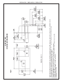
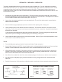
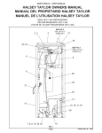
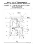
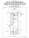
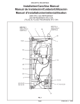
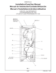
EDFP210FP*B
EDFP214FP*B
EDFP217FP*B
Installation/Care/Use Manual
EDFP210FPC EDFP214FPC EDFP217FPC
™
Soft Sides Freeze Resistant Fountains
EDFP210FPC
EDFP214FPC
EDFP217FPC
Installer
To assure you install this model easily and correctly, PLEASE READ THESE SIMPLE
INSTRUCTIONS BEFORE STARTING THE INSTALLATION. CHECK YOUR INSTALLATION FOR COMPLIANCE WITH PLUMBING, ELECTRICAL AND OTHER APPLICABLE
CODES. After installation, leave these instructions inside the fountain for future reference.
This Freeze Resistant Fountain is shipped in two separate cartons. The second carton(s)
contains the Freeze Resistant Package(s) LKFRB1 that are installed on an interior
heated wall. The interior space must maintain a minimum temperature of 50° F (10° C).
Refer to the Freeze Resistant Package for the rough-in dimensions for installation.
IMPORTANT
ALL SERVICE TO BE PERFORMED BY AN AUTHORIZED SERVICE PERSON
IMPORTANT! INSTALLER PLEASE NOTE.
THE GROUNDING OF ELECTRICAL EQUIPMENT SUCH AS TELEPHONE, COMPUTERS, ETC. TO
WATER LINES IS A COMMON PROCEDURE. THIS GROUNDING MAY BE IN THE BUILDING OR MAY
OCCUR AWAY FROM THE BUILDING. THIS GROUNDING CAN CAUSE ELECTRICAL FEEDBACK
INTO A FOUNTAIN, CREATING AN ELECTROLYSIS WHICH CAUSES A METALLIC TASTE OR AN
INCREASE IN THE METAL CONTENT OF THE WATER. THIS CONDITION IS AVOIDABLE BY USING
THE PROPER MATERIALS AS INDICATED. ANY DRAIN FITTINGS PROVIDED BY THE INSTALLER
SHOULD BE MADE OF PLASTIC TO ELECTRICALLY ISOLATE THE FOUNTAIN FROM THE BUILDING
PLUMBING SYSTEM.
97565C (Rev. J - 8/07)
97565C (Rev. J - 8/07)
LEGEND
A = MOUNTING BOLT LOCATIONS
(4) (3/8" DIA. NOT PROVIDED)
B = 7/8" DIA. (22mm) HOLE FOR
WATER SUPPLY TUBE
C = 7/8" DIA. (22mm) HOLE FOR
OPERATING CABLE
D = 1-3/4" (44mm) HOLE FOR
WASTE LINE
FIG. 1
FINISHED FLOOR
EDFP210FP/EDFP214FP
MOUNTING BOLT AND ACCESS HOLE LAYOUT
EDFP210FP*B
EDFP214FP*B
PAGE 2
EDFP217FP*B
FINISHED FLOOR
EDFP214FP*B
PAGE 3
1. Wall should already be framed for the fountain using dimensions shown in Fig. 1. Shown dimensions pertain to installation location.
These dimensions are required for compliance with ANSI Standard A117.1. and ADA (Framing shown for reference only).
2. Remove bottom cover from fountain and save the screws.
3. Install the fountain using bolts and washers (not provided). Tighten securely.
4. Attach drain tube to fountain and cut to required length using the freeze resistant box as a guide.
5. Install freeze-resistant box - see box instructions.
6. Replace bottom cover.
FIG. 2
EDFP210FP/EDFP214FP
ROUGH-IN DRAWINGS
EDFP210FP*B
EDFP217FP*B
97565C (Rev. J - 8/07)
97565C (Rev. J - 8/07)
LEGEND
A = 3/8" DIA. (10mm) SLOTS (FOR MOUNTING
UPPER HANGER BRACKET)
B = 7/8" DIA. (22mm) HOLE FOR WATER
SUPPLY TUBE
C = 7/8" DIA. (22mm) HOLE FOR OPERATING
CABLE
D = MOUNTING BOLT LOCATIONS (8) (3/8" DIA.
NOT PROVIDED)
E = 1-3/4" (44mm) HOLE FOR WASTE LINE
FIG. 3
FINISHED FLOOR
EDFP217FP
MOUNTING BOLT AND ACCESS HOLE LAYOUT
EDFP210FP*B
EDFP214FP*B
PAGE 4
EDFP217FP*B
FINISHED FLOOR
EDFP214FP*B
PAGE 5
1. Wall should already be framed for the fountains using dimensions shown in Fig. 3. Shown dimensions pertain to installation location.
These dimensions are required for compliance with ANSI Standard A117.1. and ADA (Framing shown for reference only).
2. Remove bottom covers from fountains and save the screws.
3. Install the fountains using bolts and washers (not provided). Tighten securely.
4. Attach drain tubes to fountains and cut to required length using the freeze resistant boxes as guides.
5. Install freeze-resistant boxes - see box instructions.
6. Replace bottom covers.
FIG. 4
EDFP217FP
ROUGH-IN DRAWINGS
EDFP210FP*B
EDFP217FP*B
97565C (Rev. J - 8/07)
EDFP210FP*B
EDFP214FP*B
EDFP217FP*B
CABLE SHEATH ADJUSTMENT
To Increase Free Play
To Reduce Free Play
FIG. 5
FIG. 6
See Fig. 9
See Fig. 5
FIG. 7
FIG. 8
97565C (Rev. J - 8/07)
FIG. 9
PAGE 6
EDFP210FP*B
EDFP214FP*B
EDFP217FP*B
The freeze resistant package must be mounted on an interior wall in a heated area. The room temperature of the interior
heated area must be 50° F (10° C) or higher. The freeze resistant package may be surface or recessed mounted. If recess
mounted the surface of the cover must be flush with the interior wall surface. The package is furnished with screws for
mounting the cover to the box. If the box is recess mounted, do not fasten the top and bottom of the cover to the box. Use
the holes on the front only.
1. Assemble the operating cable to the fountain bracket. (Fountain should be mounted to exterior wall) Create a loop in
the cable and thread the free end of the cable through the wall into the freeze resistant box. The adjustment nuts should
be in the middle of threaded area on the operating cable. See Figure 9
2. Connect free end of operating cable to the valve-operating bracket. The end of the cables must be recessed into the
indents on the pivot brackets.
3. Remove cable free play by adjusting the jam nuts on the ends of the operating cable. See Figure 6
4. Connect water line from fountain bubbler into freeze resistant box. The connection to the box uses a quick connect
water fitting. Position the water line, in the fountain, to drain back into interior mounted box. Any water left standing, in
the exterior line, can freeze.
To insert tubing, push tube straight into fitting until it reaches a positive stop. To remove tubing from the fittings, relieve
water pressure, push in on dark gray collar while pulling out on the tubing. See Figure 11
5. Connect drain and water supply lines to the freeze resistant fountain. Refer to Figure 1 for component positions. Inline
strainer must be used on the inlet water line.
Start-up
1. Turn on building water supply and check all connections for leaks. Repair as required.
2. Stream height is factory set at 35 PSI. If stream height needs to be changed adjust the regulator in the freeze resistant
package. Clockwise adjustment raises stream height, counter clockwise adjustment will lower stream.
3. Adjust operating cable as required. Cable system should have a minimal amount of free play to allow for proper valve
operation. If the system is too tight the valve will stay in the on position creating constant water flow. Too much free
play will result in non-operation of the valve with the push-buttons.
4. Note: Water from the drain back tube in the freeze resistant package, will continue to run while the valve is actuated.
5. After cable system is adjusted properly stuff flexible insulation into any openings between the outside wall and the
interior box.
6. Recheck all connections. If all connections are leak free replace cover(s) on the freeze resistant box(es) and fountain(s).
1/4" O.D. TUBE
WATER INLET
3/8" O.D. UNPLATED
COPPER TUBE CONNECT
COLD WATER SUPPLY
NOTE: WATER FLOW DIRECTION
FIG. 10
OPERATION OF QUICK CONNECT FITTINGS
BUILDING WATER
INLET
SIMPLY PUSH IN
TUBE TO ATTACH
SERVICE STOP
(NOT FURNISHED)
TUBE IS
SECURED
IN POSITION
PUSH IN COLLET
TO RELEASE TUBE
PUSHING TUBE IN BEFORE
PULLING IT OUT HELPS TO
RELEASE TUBE
FIG. 11
PAGE 7
97565C (Rev. J - 8/07)
EDFP210FP*B
EDFP214FP*B
EDFP217FP*B
PARTS LIST
ITEM NO.
PART NO.
DESCRIPTION
1
2
3
4
5
6
7
8
9
10
11
12
13
14
15
16
100322740560
75570C
15009C
27057C
27945C
27946C
40045C
40206000
98118C
45662C
45663C
50198C
51667C
55919C
70425C
28782C
28783C
55000661
55000665
27971C
75672C
72000833
56092C
75520C
56280C
GASKET
SCREW-#10 X .50 PINNED TORX
NIPPLE ASSY
BRACKET-REGULATOR MOUNTING
BRACKET-BASIN
BRACKET-BASIN PIVOT
HEX NUT 1-5/16
RETAINER
BUBBLER ASSEMBLY
PUSH BUTTON
SLEEVE-PUSH BUTTON GUIDE
SNAP BUSHING
BUMPER-REG. VALVE ASSY
PUSH BUTTON (EXTENSION)
PIVOT ROD
FOUNTAIN ARM - SHORT
FOUNTAIN ARM - LONG
BOTTOM COVER PLATE - SHORT
BOTTOM COVER PLATE - LONG
BACK PANEL ASSY - EDFP217FPC
CAP SCREW
WASTE ARM ASSY
POLY TUBING (CUT TO LENGTH)
BIT - PINNED TORX
EDGE TRIM
17
18
19
20
NS
NS
21
18
SEE FIG. 14
SEE FIG. 13
21
20
2, 17
FIG. 12
8
6
FIG. 13
13
15
7
5
12
4
16
12
14
11, 19
9
10
21
FIG. 14
1
3
FOR PARTS, CONTACT YOUR LOCAL DISTRIBUTOR OR CALL 1.800.323.0620
ELKAY MANUFACTURING COMPANY • 2222 CAMDEN COURT • OAK BROOK, IL 60523 • 630.574.8484
97565C (Rev. J - 8/07)
PAGE 8