1
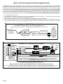
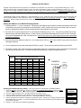
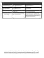
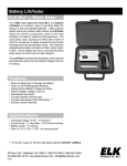
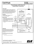
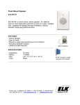
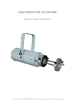
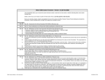
Keypad Arming Station
ELK-M1KPAS
APPLICATION
The ELK-M1KPAS is an easy to use, slim line keypad for use in arming
and disarming any of the M1 Family Cross Platform Controls. It fits into
a single gang electrical box and utilizes any standard decorator style
faceplate. It handles basic functionality and displays system status
using 3 LEDs: Green for "Ready", Yellow for "Trouble", and Red for
"Armed". The low cost and small footprint of the M1KPAS Arming
Station makes it ideal for use as an alternative to the larger and more
costly LCD keypads. It is particularly well suited for partitioned jobs
such as an office, workshop, garage, etc., where full functionality is not
necessarily required. The 12 button keypad is backlighted with blue
LEDs and has quick arm keys for Exit (Away) and Stay. It also has a
"F" key (function key) for use in in activating 1 of 6 programmable
function operations.
FEATURES
!
!
!
!
!
!
!
Blue/white Backlighted 12 button keypad
Access to six (6) Programmable Functions
Operates from the M1/EZ8 'RS-485' Data Bus
Built-in Piezo Mini Sounder
Quick arm keys for Exit and Stay
Flush mounts into a standard electrical box. **
Utilizes a standard decorator style electrical cover plate (not
included).
SPECIFICATIONS
!
!
!
!
!
Connection: 4 Pin Plug-in "Flying Lead" Connector (Included)
Color: White
Operating Voltage: 13.8 VDC
Current Draw: Less than 30 mA with min. activity - 44 mA fully active
Size: 4.658" W x 5.5" H x .95" D (.375" D with recess mount)
Features and Specifications subject to change without notice.
** The local AHJ (authority having jurisdiction) or State and local regulations may prohibit the installation of a M1KPAS
Arming Station into an electrical box together with any high voltage circuits. In some cases a special dual voltage box or
divider partition (separator) may be successfully used. One known manufacturer of these is "Carlon". Visit your local
home center or electrical supply company for availability.
Elk specifically warns against improper use, particularly
unauthorized installation or servicing in conjunction with high voltage circuits except by licensed and qualified high
voltage personnel. Elk is not responsible for damages or harmful consequences. Always consult the local AHJ and
follow state and local regulations. In some cases the best solution is to install the M1KPAS into a separate and dedicated
single gang box.
PO Box 100 • Hildebran, NC 28637 USA • 828-397-4200 Voice • 828-397-4415 Fax
http://www.elkproducts.com • email: [email protected]
L610 08/24/06
Page 1
INSTALLATION OF ELK-M1KPAS KEYPAD ARMING STATION
The M1KPAS mounts into a standard electrical box. Depending upon local/state regulations it may be permissible to mount an M1KAS
alongside other electrical devices provided that a special low voltage divider insert and/or low voltage combo box is utlized. Select a location
with an ambient temperature range between 32° and 120° F (0° to +49° C). Avoid direct sunlight if possible. CAT5 or CAT6 wire (4 pair,
8 conductor) is highly recommended for all data bus cables and the extra wires may be required for data return paths where multiple
homeruns or devices are installed. NOTE: Please refer to the M1 or EZ8 Installation Manual for important information about Data Bus
termination when multiple homerun cables are installed. Minimum conductor size is 22 or 24 gauge. Maximum resistance per wire is
25 Ohms. Device placement beyond 1000' is not recommended. DO NOT SPLICE OR CONNECT WIRES WITH THE CONTROL POWER ON.
1. Turn off all power to the control.
2. Splice the Black, Red, White, and Green wires of the 4-wire cable assembly to the data bus wires. Plug the connector onto the back
of the M1KPAS. Tuck the wires and splices neatly into electrical box.
3. Fasten the top and bottom mounting ears to the electrical box using flat head #6 machine screws.
4. Turn on the power to the control. One or more of the lights on the M1KAS may be illuminated indicating the unit has power, however
it will not become operation until it has been assigned an address and has been enrolled into the Control. See steps on next page.
Hookup Diagram for M1KPAS Keypad Arming Station
(see M1/EZ8 Instruction Manuals for multiple Keypad hookups.)
Splice wires from data bus cable to Keypad assembly using ELK-900-2 "B" Connectors.
ELK-M1KPAS
To Control
Data Bus Cable
CAT5 or CAT6
Recommended
ELK-WO40A 4 Wire
Keypad Cable Assembly
RED
4
GREEN
WHITE
BLACK
RE: Data Bus
Termination Note
RS-485 DATA BUS
+VKP
DATA A
DATA B
NEG
EGND
J2
DATA BUS
J1
-
NEG
DATA B
DATA A
+12V
Pin 1
Data Bus E.O.L. Termination is Very Important
Keypad 1
RS-485 Data Bus (Max. length is 4000 ft.
Max. bus devices vary by control.)
ELK-M1KPAS
ELK-M1XIN
RED
GREEN
WHITE
ELK-M1XOV
DO NOT Jumper
Terminate these devices.
Jumper
Terminate
these two
devices.
Keypad 3
BLACK
DATA BUS TERMINATION IS VERY IMPORTANT!!
Ideal setup is 2 home run cables with daisy chained devices. The last device on each cable MUST have a terminating resistor
installed (activated) via the 2 pin header/jumpers marked JP1 on M1KPAS & M1KP2 Keypads and expanders, JP2 on M1KP
Keypads. Place a black shorting cap from hardware pack onto the 2 pins to install a 120 Ohm resistor across data lines A & B.
NOTE: Place a shorting cap on JP3 of Main Board if there is only 1 data bus cable. See diagrams on multiple cables.
WARNING! The RS485 Data Bus must NEVER have more that 2 terminating resistors header/jumpers installed.
Reliability and response will be negatively affected!
Temporary Connection "Plug-in" jacks for RS-485 Data Bus (J1 & J2)
Local connection for Data Bus Devices ie: Keypads, etc. for testing purposes only.
Diagram for Daisy Chain Connection of Data Bus Devices Using Two (2) Home Run Cables
The ideal way to connect multiple home run cables is with an ELK-M1DBH Data Bus Hub. It accepts CAT5 or CAT6 cable with RJ45 plugs on the ends.
It does all the work of series connecting the DATA lines A & B and provides a clean, organized management of the data bus wires.
Page 2
Address and Enrollment
Keypads and expander devices that operate on the RS-485 4-wire data bus must each have a unique address setting from 1 to 16
within their device TYPE. Keypads are device TYPE 1, input (zone) expanders are TYPE 2, output expanders are TYPE 3, etc. The
purpose of device types is so that the address numbers can be re-used in each different device type. It is OK to have a Keypad, a Zone
Expander, and a Output Expander all set to address 2 on the same data bus since each device is a different device type. It is NOT OK
to have duplications of addresses within the same device type. I.E. Multiple keypads on a control cannot be set to 'like' addresses.
The M1KPAS is factory preset to address 16. Valid addresses are 1 to 16. Whenever an M1 control is powered up for the first time only
the first keypad (address 1) is automatically enrolled. Any additional keypads must be manually enrolled from “Menu 1 - Bus Module
Enrollment”. Before enrolling each device will need to be set with an address.
Setting the Address of an M1KPAS Arming Station:
1. Press and hold the " * " key for 10 seconds. This will place the M1KPAS arming station into setup (bootloader) mode which
is indicated by the numeric keys blinking On and Off together. NOTE: Another way to access the setup mode is to remove
power by unplugging the data bus cable and applying power while holding any key pressed.
2. Once the unit is in setup mode press the "F" key followed immediately by the "1" key. The unit will now display its current
address setting utilizing the Ready (Green), Trouble (Yellow), Armed (Red) LEDs and the EXIT and STAY keys. Each LED
or key has an assigned binary value. See table below. The EXIT key (value of 16) will be lighted by itself when the M1KPAS
is fresh from the factory.
3. Enter the desired new address number from 1 to 16 and press the EXIT key. OR Press the EXIT key by itself to exit without
changing the address.
4. To exit completely from the setup mode press the EXIT key again. The numeric keys will stop blinking On and OFF.
5. The Ready, Trouble, Armed, Exit, and Stay keys will all begin lighting in a clockwise process to indicate that the keypad has
not been enrolled with the control. Proceed to the ENROLLING process to make the keypad operational.
Keypad
Address
1
2
3
4
5
6
7
8
9
10
11
12
13
14
15
16
When the M1KAS is in setup mode the LEDs will display the
address setting in Binary Representation
Armed
(Red) = 1
Trouble
(Yellow) = 2
On
On
On
On
On
On
On
On
-
On
On
On
On
On
On
On
On
-
Ready
(Red) = 4
On
On
On
On
On
On
On
On
-
Stay (Blue)
=8
On
On
On
On
On
On
On
On
-
Exit (Blue)
= 16
On
EXAMPLE
ELK-M1KPAS
Ready
Trouble
Armed
Address 3
would be
indicated by
these 2 LEDs
being ON
Enrolling the M1KPAS Arming Station: (This step requires an LCD Keypad or the ElkRP software)
1.
2.
3.
4.
5.
6.
Press the ELK key, then press 9 (or scroll up) to display 9 - Installation Programming. Press the RIGHT
arrow key to select this menu. The Installer Program Code (PIN) must be entered to access this menu.
Enter the Installer Program Code. (See M1 Manual for the default Code)
The first Installer Programming menu displayed will be "Bus Module Enrollment"
Press the RIGHT arrow key to select this menu. "Enrolling Bus Modules" will display
The M1 will transmit an enrollment message to all data bus devices, following by a display showing the total
Bus Modules that are enrolled. To view the enrolled devices and/or remove a device press the RIGHT arrow
key to select Edit mode.
Press the * or Exit keys to exit Installer Programming.
1234567890123456789012345
1234567890123456789012345
1234567890123456789012345
1234567890123456789012345
Auth. Required
1234567890123456789012345
1234567890123456789012345
1234567890123456789012345
Enter Valid Pin
1234567890123456789012345
1234567890123456789012345
1234567890123456789012345
1234567890123456789012345
1234567890123456789012345
1234567890123456789012345
01-Bus Module
1234567890123456789012345
1234567890123456789012345
1234567890123456789012345
Enrollment
1234567890123456789012345
1234567890123456789012345
1234567890123456789012345
1234567890123456789012345
1234567890123456789012345
1234567890123456789012345
XX Bus Modules
1234567890123456789012345
1234567890123456789012345
1234567890123456789012345
1234567890123456789012345
Enrolled, Editr
1234567890123456789012345
Page 3
Troubleshooting and Diagnostics
Symptom
No visual or audible feedback
when buttons are pressed.
Ready, Trouble, Armed, Stay, and
Exit LEDs are lighting in a
clockwize rotation.
Numeric keys All Flashing
Erratic operation. LEDs and
buttons do not seem to be
responding properly.
Potential Cause
Remedy (Things to try)
Keypad is not communicating with the
control. Power may be off or wiring
unplugged.
Check wiring and plug connections. Verify power at
connections using a voltmeter.
Keypad is communicating but it has not
been enrolled with the Control.
Use the bus module enrollment procedure to enroll the
keypad into the Control.
Keypad is in the Setup Mode is waiting for
an address setting.
Refer to the instructions for address setting OR press the
Exit key to return to regular operation.
Improper data bus termination, improper
wiring or wiring, OR another keypad already
exists at this data bus address.
Check for: a. Reversed data bus wires. b. Improper data
bus termination (see manual). c. Duplicate address
"conflict" with another keypad. If all else fails swap with
another keypad making sure to re-address and re-enroll. If
problem goes away the old keypad may be defective. If
problem persists contact Tech Support.
Please Note: The back page of this booklet is designed so that it may be separated from the rest of the pages.
It may then be folded in half to convert into a User Operation Guide for the M1KPAS Arming Station. It may be
placed inside or with the regular M1/EZ8 User Guide book as a suppliment to those complete instructions.
Secure all protected doors and windows.
1. Enter a User code.
2. The Exit key will light and the exit tone will start.
3. As long as there is not exit through any delayed doors the Stay light will come on and
the Exit light will go off at the end of the exit delay time. The system is now armed in
the Stay mode.
Auto Stay Arming
(Optional) If this feature was enabled by your installer, it will automatically change the arm
mode from Away to Stay if none of the perimeter delayed doors are opened during the exit delay
countdown time.
Secure all protected doors and windows.
1. Enter a User code.
2. The Armed and Exit lights will illuminate and the exit tone will start.
3. Press the Stay key. The key will light up. All interior zones will be excluded and the
exit tone will be silenced. Delayed entry/exit zones will still be delayed.
4. (Option, may not be enabled) Additional presses of the Stay key may allow scrolling to
different modes of Stay arming if enabled by your installer. Additional modes are Stay
Instant, Stay Night, and Stay Night Instant. The is no visual indication for the optional
stay modes.
Arming in the “Stay” Mode
Stay mode arming is intended for use when the premises is occupied. All perimeter doors
and windows are armed, and all interior zones are excluded.
Arming in the “Vacation” Mode
Vacation mode is a second level of Away mode. It can be used to activate energy saving
automation features when the building will not be occupied for an extended period of time. After
arming, pressing the Exit button at any time during the exit delay time to change the armed mode to
vacation. Unfortunately there is no visual indication at the M1KPAS for vacation mode.
During the last 10 seconds of the exit delay time the exit tone will beat faster to warn you that the time is
about to expire. If you feel that you will be unable to get out and close the exit door in time we recommend that
you return to the keypad, disarm, and rearm.
Secure all protected doors and windows.
1. Enter a User code.
2. The Armed and Exit lights will illuminate and the exit tone will start.
4. Leave the premises during the exit delay.
5. At the end of the exit delay the alarm system will be armed Away.
Away mode arming is the highest arm level, intended for use when the premises is unoccupied. Both
perimeter and interior zones will be armed. The Ready light must be on or flashing for the alarm system to be
armed.
Arming in the “Away” Mode
(Inside Fold Line)
Press the Exit or Stay key.
The Armed and mode light (Exit or Stay) will illuminate just as if you had entered your
user code.
After an alarm has been silenced by a valid user code, a valid user code must be
entered a second time to “Acknowledgment” the alarm.
Disarming and Silencing During an Alarm
1. Proceed directly to the keypad.
2. Enter a user code.
3. The keypad entry tone and the alarm siren/bell will stop.
4. When the Armed light turns off the alarm system is disarmed.
5. If you are certain the alarm was accidental, contact the Central Monitoring Center to
avoid a false dispatch of the authorities.
Disarming and Silencing After an Alarm
1. Proceed directly to the keypad.
2. Enter your user code.
3. The entry delay tone should stop.
4. When the Armed light turns off the alarm system is disarmed.
If a valid user code is not entered before the entry delay time expires, an alarm will occur.
If this should occur proceed as follows:
Disarming
1. Proceed directly to the keypad.
2. Enter a valid user code.
3. The entry delay tone should stop.
4. When the Armed light turns off the alarm system is disarmed.
Disarming and Resetting the System
After entering the premises through one of the assigned Entry delayed zones, the keypad
will sound a continuous entry delay tone. Refer to the System Notes for the amount of entry time
available.
1.
2.
Changing Stay Modes While Armed
(Optional) If this feature was enabled by your installer, it permits various levels of Stay
mode arming to be enabled (scrolled) without having to first disarm the system. The additional
Stay mode arming levels may include: Instant, Stay Night, and Stay Night Instant.
Secure all protected doors and windows.
1. Press the Exit or Stay key.
2. The Armed and mode light (Exit or Stay) will illuminate just as if you had entered your
user code.
Using the Quick Arm
(Optional) If this feature was enabled by your installer, it will allow arming in either the
Away or Stay modes without having to enter your user code. For security reasons however, a
user code is always required to disarm.
SYSTEM NOTES
Central Monitoring Station: _______________________________
Acct. # ______
Phone: ___________________
Installation Company: ________________________________________________
Address: ________________________________
Zip: ___________
Exit Delay 2 Timer: _______
St: _______
Exit Delay 1 Timer in seconds: _______
Entry Delay 2 Timer: _______
City: ___________________________________
Entry Delay 1 Timer in seconds: _______
Burglary Alarm (Audible) Cutoff Timer in minutes: _______
Fire Alarm (Audible) Cutoff Timer in minutes: _______
F Key + 2 Function: _______________________ Single Press? Y or N
F Key + 1 Function: _______________________ Single Press? Y or N
Silent? Y or N
Silent? Y or N
Silent? Y or N
6 digits ____
F Key + 3 Function: _______________________ Single Press? Y or N
Silent? Y or N
or
F Key + 4 Function: _______________________ Single Press? Y or N
Silent? Y or N
4 digits ____
F Key + 5 Function: _______________________ SinglePress? Y or N
Silent? Y or N
User Code Digits
F Key + 6 Function: _______________________ SinglePress? Y or N
Ready
Trouble
Armed
ARMING STATION OPERATION GUIDE
Ready Light - Light is ON when all burglar zones are secure and the
system is OK for arming. If this light is OFF, one or more zones are
violated (not secure) and the system cannot be armed. If light is
FLASHING it indicates that the system may be "Force Armed". Force
arming permits partial security even though one or more zones are
violated. Force armed zones are temporarily bypassed. If a force
armed zone becomes secure it will be re-instated into the system. For
maximum security, all zones should be secured before the system is
armed.
Trouble Light - Light is ON when any system trouble (AC Fail, Low
Battery, etc.) exists on the system. In addition, this light will be ON if
a zone is manually bypassed. NOTE: The M1KPAS Arming Station
cannot be used to manually bypass or unbypass a zone. It will be
necessary to have an LCD display keypad (M1KP or M1KP2 to
diagnose trouble indications.
Armed Light- Light is ON when the system is armed. The mode of
arm will be indicated by the lighted Exit or Stay pushbuttons. Light is
OFF when the system is disarmed. If an alarm activation occurs this
light will blink as an alarm memory indication until a user code is
entered to acknowledge the alarm.
Exit Key - The light behind this key will be ON when the system is armed in the Away (not occupied) mode.
All perimeter and interior zones should be active in the away mode.
Stay Key - The light behind this key will be ON when the system is armed in the Stay (occupied) mode. Only
perimeter (doors and windows) zones should be active. Interior zones are ignored in the stay mode.
* Key - This key serves as a clear or reset key. If an error is made while entering digits, pressing this key
clears the error. Three presses is a master clear.
# Key - This key is currently not used on the M1KPAS.
"F" Function Key - To activate any one of the 6 programmable special functions you must press the "F" key
followed by any of the keys 1 thru 6 within a 4 second time window. The activation is programmed by the
installer for special events or conditions such as Fire, Police, or Medical emergency. These functions may also
be used for non-alarm type applications such as: gate or door openers, lights, irrigation controls, etc. Activation
may be programmed for single or double press, which helps prevent accidental activation. If double press is
programmed, it will be necessary to repeat the exact same keystrokes twice, back to back in a short time
period. The double press is used as a safeguard against accidental activation.
User Codes
!
User Codes are required for arming, disarming, and to authorize certain features of your system. User
codes can be either 4 or 6 digits (refer to System Notes).
!
If a mistake is made while entering a user code, press the asterisk ( * ) key and enter the code again.
!
To prevent someone from hunting for a code the system can be set to temporarily lockout the keypad
after repeated incorrect codes. Consult your installer or installation record sheet for the number of
incorrect attempts allowed.
Checking the Ready Status
!
When the Ready light is off, one or more zones are violated. The system cannot be armed until you
secure or bypass the violated zone(s).
!
A display style keypad will be required in order to identify violated zones.
!
When the Ready light is on steady the alarm system is ready to be armed.
!
If the Ready light is flashing, it indicates the system can be armed even though one or more zones are
violated. This only occurs if the violated zones are programmed as force-armable. Arming will temporarily
exclude these violated zones from the system. If a force armed zone becomes secure while the system
is armed, it will automatically become live, meaning that it can activate an alarm if violated. This feature
is handy for a garage door. The system can be armed while the door is up. After backing out of the
garage and closing the door, the garage door will become normal and it will be re-included into service.