1
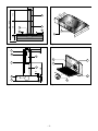
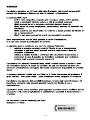
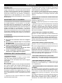
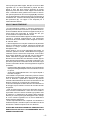
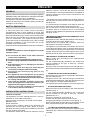
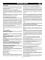
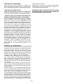
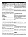
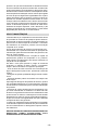
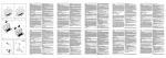
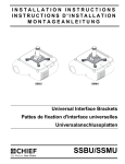
I
CAPPA ASPIRANTE - Istruzioni per l'uso
D
DUNSTABZUGSHAUBE - Gebrauchsanweisung
E
CAMPANA EXTRACTORA - Manual de utilización
F
HOTTE DE CUISINE - Notice d'utilisation
GB
COOKER HOOD - User instructions
NL
AFZUIGKAP - Gebruiksaanwijzing
P
COIFA ASPIRANTE - Manual do usuário
-2-
445
190
350
224
45
355
505 : 950
150
E
C
45
F
M
A
D
S
505
523
B
150
P
Fig.1
Fig.3
115
32
G
Z
E
F
H
490
F
20
25
90°
100
150
L
C
25
P
67
B
A
G
Fig.2
Fig.4
-3-
-4-
ITALIANO
GENERALITA'
Leggere attentamente il contenuto del presente libretto
in quanto fornisce importanti indicazioni riguardanti la
sicurezza di installazione, d'uso e di manutenzione.
Conservare il libretto per ogni ulteriore consultazione.
L'apparecchio è stato progettato per uso in versione
aspirante (evacuazione aria all'esterno ), filtrante (riciclo
aria all'interno)
AVVERTENZE PER LA SICUREZZA
1. Fare attenzione se funzionano contemporaneamente
una cappa aspirante e un bruciatore o un focolare
dipendenti dall'aria dell'ambiente ed alimentati da
un'energia diversa da quella elettrica, in quanto la cappa
aspirando toglie all'ambiente l'aria di cui il bruciatore o il
focolare necessita per la combustione. La pressione
negativa nel locale non deve superare i 4 Pa (4x10⁻⁵
bar). Per un funzionamento sicuro, provvedere quindi ad
un'opportuna ventilazione del locale. Per l'evacuazione
esterna attenersi alle disposizioni vigenti nel vostro paese.
2. ATTENZIONE !
In determinate circostanze gli elettrodomestici possono
essere pericolosi.
A) Non cercare di controllare i filtri con la cappa in
funzione
B) Non toccare le lampade dopo un uso protratto
dell'apparecchio
C) E' vietato cuocere cibi alla fiamma sotto la cappa
D) Evitare la fiamma libera, perchè dannosa per i
filtri e pericolosa per gli incendi
E) Controllare costantemente i cibi fritti per evitare
che l'olio surriscaldato prenda fuoco
F) Prima di effettuare qualsiasi manutenzione,
disinserire la cappa dalla rete elettrica.
ISTRUZIONI PER L'INSTALLAZIONE
• Collegamento elettrico
L'apparecchio è costruito in classe II, perciò nessun
cavo deve essere collegato alla presa di terra.
L'allacciamento alla rete elettrica deve essere eseguito
come segue:
MARRONE = L linea
BLU = N neutro
Se non prevista, montare sul cavo una spina normalizzata
per il carico indicato nella etichetta caratteristiche. Se
provvista di spina, fare in modo che sia facilmente
accessibile dopo l’installazione dell’apparecchio.
Nel caso di collegamento diretto alla rete elettrica è
necessario interporre tra l'apparecchio e la rete un
interruttore onnipolare con apertura minima tra i contatti
3 mm, dimensionato al carico e rispondente alle norme
vigenti.
• L'apparecchio deve essere installato ad un'altezza
minima di 650mm dai fornelli.
I
Se dovesse essere usato un tubo di connessione
composto di due o più parti, la parte superiore deve
essere all'esterno di quella inferiore.
Non collegare lo scarico della cappa ad un condotto in
cui circoli aria calda o utilizzato per evacuare fumi degli
apparecchi alimentati da un'energia diversa da quella
elettrica.
• MONTAGGIO DELLA CAPPA NELLA PARTE INFERIORE
DI UN PENSILE
Eseguire 4 fori diametro mm. 6 nel fondo del pensile come
illustrato nel disegno fig. 3.
Montare la cappa sotto il pensile con 4 viti idonee al tipo
di mobile.
L’ apparecchio è provvisto di 2 uscite dell’ aria, una situata
nella parte superiore e l’ altra nella parte posteriore
utilizzabili a secondo delle vostre esigenze. Sono forniti
a corredo un anello di raccordo (C), al quale collegare il
tubo di connessione, ed un tappo (A) per chiudere l’ uscita
dell’ aria non utilizzata.
• MONTAGGIO DELLA CAPPA ALLA PARETE
Eseguire 4 fori (B-P) rispettando le quote indicate in fig.
2.
Per i vari montaggi utilizzare viti e tasselli ad espansione
idonei al tipo di muro (es. cemento, cartongesso ecc.)
Appendere la cappa alla parete utilizzando i 2 fori (B) fig.2.
Fissare definitivamente la cappa alla parete utilizzando i
due fori di sicurezza inferiori (P).
• MONTAGGIO TUBI RACCORDO (OPTIONAL)
Eseguire 4 fori (G-H) rispettando le quote indicate in fig.
2.
Per i vari montaggi utilizzare viti e tasselli idonei al tipo di
muro (es. cemento, cartongesso ecc.).
Bloccare la staffa (Z) alla parete fig. 2.
Posizionare i due raccordi verticalmente sulla cappa.
Appendere il raccordo (F) utilizzando i 2 fori (H) fig. 2.
Sfilare il raccordo (E) dal raccordo (F) e bloccarlo lateralmente alla staffa (Z) con le apposite viti.
• MONTAGGIO VETRO VELETTA (OPTIONAL)
Posizionare il vetro veletta completo di supporti (V) come
indicato in fig. 1, e fissare alla cappa con le apposite viti.
• MONTAGGIO MANIGLIA (OPTIONAL)
Posizionare La maniglia (M) ed i due supporti destro (D)
e sinistro (S), come indicato in fig. 1, e fissare alla cappa
con le apposite viti.
• TRASFORMAZIONE DA CAPPA ASPIRANTE A CAPPA
FILTRANTE
Per effettuare questa trasformazione (possibile anche
dopo l’ uso con sistema aspirante), richiedere al fornitore,
se non forniti, una serie di filtri al carbone attivo. I filtri al
carbone attivo servono per depurare l’ aria che verrà
rimessa
nell’ ambiente attraverso i fori posti nella parte anteriore
della cappa. I filtri non sono lavabili o rigenerabili e
devono essere sostituiti ogni 4 mesi al massimo. La
saturazione del carbone attivo dipende dall’ uso più o
-5-
meno prolungato della cappa, dal tipo di cucina e dalla
regolarità con cui viene effettuata la pulizia del filtro
grassi. Il filtro (C) deve essere applicato al gruppo
aspirante posto all’ interno della cappa centrandolo ad
esso e ruotandolo di 90 gradi fino allo scatto d’ arresto.
Per questa operazione rimuovere la griglia (G). Chiudere
con gli appositi tappi l’ apertura superiore e posteriore di
uscita dell’ aria; ruotare la levetta (L) dalla posizione (A)
alla posizione (F). La cappa è così disposta per il
funzionamento filtrante.
USO E MANUTENZIONE
• Si raccomanda di mettere in funzione l'apparecchio
prima di procedere alla cottura di un qualsiasi alimento.
Si raccamanda di lasciar funzionare l'apparecchio per 15
minuti dopo aver terminato la cottura dei cibi, per
un'evacuazione completa dell'aria viziata.
Il buon funzionamento della cappa è condizionato da una
corretta e costante manutenzione; una particolare
attenzione deve essere data al filtro antigrasso e al filtro
al carbone attivo.
• Il filtro antigrasso ha il compito di trattenere le particelle
grasse in sospensione nell’aria, pertanto è soggetto ad
intasarsi in tempi variabili relativamente all’uso
dell’apparecchio.
Il filtro acrilico, che si trova appoggiato alla griglia, va
sostituito quando le scritte, visibili attraverso la griglia,
cambiano colore e l'inchiostro si espande; il nuovo filtro
deve essere applicato in modo tale che le scritte siano
visibili attraverso la griglia dall'esterno della cappa.
Nel caso in cui i filtri acrilici non abbiano le scritte, oppure
siano presenti filtri metallici o a pannello in alluminio, per
prevenire il pericolo di eventuali incendi, al massimo ogni
2 mesi è necessario lavare i filtri eseguendo le seguenti
operazioni:
- togliere il filtro dalla griglia e lavarlo con una soluzione
di acqua e detergente liquido neutro lasciando rinvenire
lo sporco.
- Sciacquare abbondantemente con acqua tiepida e
lasciare asciugare.
I filtri metallici e/o pannello in alluminio possono essere
lavati anche in lavastoviglie. Dopo alcuni lavaggi, se i filtri
sono in alluminio o pannello in alluminio, si possono
verificare delle alterazioni del colore. Questo fatto non dà
diritto a reclamo per l'eventuale loro sostituzione.
In caso di inadempienza delle istruzioni di sostituzione e
di lavaggio si può verificare il rischio di incendio dei filtri
antigrasso.
• I filtri al carbone attivo servono per depurare l'aria che
viene rimessa nell'ambiente. I filtri non sono lavabili o
rigenerabili e devono essere sostituiti ogni quattro mesi
al massimo. La saturazione del carbone attivo dipende
dall'uso più o meno prolungato dell'apparecchio, dal tipo
di cucina e dalla regolarità con cui viene effettuata la
pulizia del filtro antigrasso
• Pulire frequentemente tutti i depositi sul ventilatore e
sulle altre superfici, usando un panno inumidito con alcool
denaturato o detersivi liquidi neutri non abrasivi.
SI DECLINA OGNI RESPONSABILITA' PER EVENTUALI
DANNI PROVOCATI DALLA INOSSERVANZA DELLE
SUDDETTE AVVERTENZE
-6-
ENGLISH
GENERAL
Carefully read the following important information regarding
installation safety and maintenance. Keep this information
booklet accessible for further consultations.
The appliance has been designed for use in the ducting
version (air exhaust to the outside), filtering version (air
circulation on the inside).
SAFETY PRECAUTION
1. Take care when the cooker hood is operating
simultaneously with an open fireplace or burner that
depend on the air in the environment and are supplied by
other than electrical energy, as the cooker hood removes
the air from the environment which a burner or fireplace
need for combustion. The negative pressure in the
environment must not exceed 4Pa (4x10⁻⁵ bar). Provide
adequate ventilation in the environment for a safe
operation of the cooker hood.
Follow the local laws applicable for external air evacuation.
2. WARNING !
In certain circumstances electrical appliances may be
a danger hazard.
A) Do not check the status of the filters while the
cooker hood is operating
B) Do not touch the light bulbs after appliance use
C) Flambè cooking is prohibited underneath the cooker
hood
D) Avoid free flame, as it is damaging for the filters
and a fire hazard
E) Constantly check food frying to avoid that the
overheated oil may become a fire hazard
F) Disconnect the electrical plug prior to any
maintenance.
G) This appliance is not intended for use by young
children or infirm persons without supervision
H) Young children should be supervised to ensure they
do not play with the appliance
I) There shall be adequate ventilation of the room
when the rangehood is used at the same time as
appliances burning gas or other fuels
L) There is a risk of fire if cleaning is not carried out
in accordance with the instructions
INSTALLATION INSTRUCTIONS
• Electric Connection
The appliance has been manufactured as a class II,
therefore no earth cable is necessary.
The connection to the mains is carried out as follows:
BROWN = L line
BLUE = N neutral
If not provided, connect a plug for the electrical load
indicated on the description label. Where a plug is
provided, the cooker hood must be installed in order that
the plug is easily accessible.
An omnipolar switch with a minimum aperture of 3mm
GB
between contacts, in line with the electrical load and
local standards, must be placed between the appliance
and the network in the case of direct connection to the
electrical network.
• The appliance must be installed at a minimum height of
650 mm from an cooker stove in case of a gashob or an
electrical hob.
If a connection tube composed of two parts is used, the
upper part must be placed outside the lower part.
Do not connect the cooker hood exhaust to the same
conductor used to circulate hot air or for evacuating
fumes from other appliances generated by other than an
electrical source.
• MOUNTING OF THE HOOD IN THE LOWER PART OF AN
HANGING CUPBOARD
Drill 4 holes of 6 mm. diameter at the bottom of the hanging
cupboard as showed in the drawing fig.3.
Fit the hood in the cabinet with 4 screws, which are
appropriate to that kind of cupboard.
The appliance is provided with 2 air outlets, one which is
in the upper part and the other on the back. Both of them
can be used according to your requirements. A connecting
ring (C), which to join the connecting pipe to,and a cover
(A) to close the air outlet, which is not used, are supplied.
• MOUNTING OF THE HOOD IN THE WALL
Make 4 holes (B-P) according to the measurements
indicated in fig. 2.
For the various assembly operations, use screws and
anchors suitable for the type of wall (eg., concrete,
plasterboard, etc.)
Hang the hood on the wall using the two holes (B) fig. 2.
Secure the hood to the wall using the two lower safety holes
(P).
• MOUNTING OF THE HOOD ON THE WALL
Drill 2 holes on the wall, which correspond to the position
(B) of the drawing fig. 1.
Hang the hood on the 2 holes by using the screws and
dowels with expanding plug ,which are aprropriate for that
kind of wall (ex. concrete, plasterboard etc.)
Fix definitely the hood through the 2 security holes (Z).
• FITTING THE PIPES (OPTIONAL)
Make four holes (G-H) according to the measurements
indicated in fig. 2
For the various assembly operations, use screws and
anchors suitable for the type of wall (eg., concrete,
plasterboard, etc.)
Secure the bracket (Z) to the wall fig. 2
Position the two pipes vertically on the hood.
Hang the pipe fitting (F) using the 2 holes (H) fig. 2
Remove pipe fitting (E) from fitting (F) and secure to the
side of the bracket (Z) with the screws provided.
• FITTING THE GLASS SECTION (OPTIONAL)
Position the glass section complete with supports (V) as
indicated in fig. 1 and secure to the hood using the screws
provided.
-7-
• FITTING THE HANDLE (OPTIONAL)
Position the handle (M) and the two right (D) and left (S)
supports, as indicated in fig. 1, and secure to the hood
using the screws provided.
• CHANGING FROM EXHAUSTING HOOD TO FILTERING
ONE
In order to make this change (possible also after the use
of the exhausting system), demand a set of carbon filters
to your dealer. Active carbon filters are necessary to
depurate the air, that will be released in the room. Filters
are not washable; they cannot be regenerated and have
to be replaced at most every 4 months. The saturation of
the activated charcoal depends on the more or less
prolonged use of the hood, on the type of cooking and on
the regularity of cleaning the grease filter. The filter (C) has
to be applied to the aspirating group, which is inside the
hood hiting the centre of the group with it and turning it of
90 degrees until the stop click is heard to lock it. Remove
the grill (G) to carry out this operation. Close with the
appropriate covers the upper and back air outlets; turn the
small lever (L) from the position (A) to the position (F). In
this way the hood is ready for the filtering function.
USE AND MAINTENANCE
• It is recommended to operate the appliance prior to
cooking.
It is recommended to leave the appliance in operation for
15 minutes after cooking is terminated in order to
completely eliminate cooking vapours and odours.
The proper function of the cooker hood is conditioned by
the regularity of the maintenance operations, in particular,
the active carbon filter.
• The anti-grease filters capture the grease particles
suspended in the air, and are therefore subject to clogging
according to the frequency of the use of the appliance.
In order to prevent fire hazard, it is recommendable to
clean the filter at a maximum of 2 months by carrying out
the following instructions:
- Remove the filters from the cooker hood and wash them
in a solution of water and neutral liquid detergent, leaving
to soak.
- Rinse thoroughly with warm water and leave to dry.
- The filters may also be washed in the dishwasher.
The aluminium panels may alter in colour after several
washes. This is not cause for customer complaint nor
replacement of panels.
• The active carbon filters purify the air that is replaced
in the environment. The filters are not washable nor reuseable and must be replaced at maximum every four
months. The saturation of the active carbon filter depends
on the frequency of use of the appliance, by the type of
cooking and the regularity of cleaning the anti-grease
filters.
• Clean the fan and other surfaces of the cooker hood
regularly using a cloth moistened with denatured alcohol
or non abrasive liquid detergent.
THE MANUFACTURER DECLINES ALL RESPONSIBILITY
FOR EVENTUAL DAMAGES CAUSED BY BREACHING
THE ABOVE WARNINGS.
-8-
ESPAÑOL
GENERALIDADES
Lea atentamente el contenido del presente libro de
instrucciones pues contiene indicaciones importantes
para la seguridad en la instalación, el uso y el
mantenimiento (Consérvelo para un posible consulta
posterior). El aparato ha sido diseñado para el uso en
versión aspiradora (evacuación de aire hacia el exterior),
filtrante (reciclaje del aire en el interior).
SUGERENCIAS PARA LA SEGURIDAD
1.Preste atención si funcionan contemporáneamente una
campana aspirante y un quemador o una chimenea que
toman el aire del ambiente y están alimentados por energía
que no sea eléctrica, pues la campana aspirante toma
del ambiente el aire que el quemador o la chimenea
necesitan para la combustión. La presión negativa del
local no debe superar los 4 Pa (4x10⁻⁵ bares). Para un
funcionamiento seguro, realice primero una adecuada
ventilación del local. Para la evacuación externa, aténgase
a las disposiciones vigentes en su país.
2. ¡ ATENCIÓN !!
En determinadas circunstancias los electrodomésticos
pueden ser peligrosos.
A) No intente controlar los filtros cuando la campana
esté funcionando.
B) No toque las lámparas después de un uso prolongado
del aparato.
C) Está prohibido cocinar alimentos a la llama debajo
de la campana.
D) Evite las llamas libres, pues resultan perjudiciales
para los filtros y pueden provocar incendios.
E) Controle en todo momento los alimentos fritos para
evitar que el aceite caliente prenda fuego.
F) Antes de realizar cualquier operación de
mantenimiento desconecte la campana de la
corriente eléctrica.
INSTRUCCIONES PARA LA INSTALACIÓN
• Instalación eléctrica
El aparato está construido en clase II, por lo tanto no se
debe e conectar ningún cable a la toma de tierra.
La conexión a la corriente eléctrica debe realizarse de la
siguiente manera:
MARRÓN = L línea.
AZUL = N neutro.
Si no está incluido, monte en el cable un enchufe
normalizado para la carga indicada en la etiqueta de las
caracteristicas.
Si está provista de enchufe,coloque la campana de tal
manera que el enchufe quede en un sitio accesible.
En caso de conexión directa a la corriente eléctrica, es
necesario interponer entre el aparato y la red un
interruptor omnipolar con abertura mínima de 3mm,
adecuado a la carga y que responda a las normas
vigentes.
E
• Debe instalarse el aparato a una altura mínima de
650mm de las placas de cocción.
Si debe usarse un tubo de conexión compuesto de dos o
más partes, la parte superior debe estar fuera de la parte
inferior.
No conecte la descarga de la campana a un conducto en
el que circúle airecaliente o que sea utilizado para evacuar los humos de aparatos alimentados por una energía
que no sea eléctrica.
• MONTAJE DE LA CAMPANA EN LA PARED INFERIOR
DE UN MUEBLE PENSIL
Practicar 4 agujeros de 6 mm de diámetro en el fondo del
mueble pensil según el dibujo de la fig. 3.
Montar la campana bajo el mueble pensil usando 4 tornillos
adecuados al tipo de mueble.
El aparato está provisto de dos salidas de aire, una en la
parte superior y otra en la parte posterior, utilizables en
función de las exigencias. Se suministran en dotación un
anillo de unión (C) al cual se acopla el tubo de conexión
y un tapón (A) para cerrar la salida de aire no utilizada.
• MONTAJE DE LA CAMPANA A LA PARED
Practicar 4 agujeros (B-P) respetando los valores indicados
en la fig. 2.
Para los diferentes montajes, utilizar tornillos y tarugos
de expansión apropiados al tipo de pared (cemento, cartón
de yeso, etc.).
Colgar la campana a la pared valiéndose de los dos
agujeros (B) fig.2.
Fijar definitivamente la campana utilizando los dos agujeros
de seguridad inferiores (P).
• MONTAJE DE LOS TUBOS DE CONEXIÓN (OPCIONAL)
Practicar 4 agujeros (G-H) respetando los valores indicados
en la fig. 2.
Para los diferentes montajes, utilizar tornillos y tarugos
de expansión apropiados al tipo de pared (cemento, cartón
de yeso, etc.).
Bloquear la abrazadera (Z) a la pared (fig. 2).
Colocar los tubos de conexión verticalmente sobre la
campana.
Colgar el tubo (F) utilizando los dos agujeros (H) (fig. 2).
Extraer el tubo (E) del tubo (F) y bloquearlo lateralmente
a la abrazadera (Z) con sus tornillos.
• MONTAJE DE LA ALETA EN VIDRIO (OPCIONAL)
Posicionar la aleta en vidrio con los soportes (V) según
la fig. 1 y fijarlo a la campana con sus tornillos.
• MONTAJE DE LA MANILLA (OPCIONAL)
Colocar la manilla (M) y los dos soportes derecho (D) e
izquierdo (S) según la fig. 1 y fijarlos a la campana con
sus tornillos.
• TRANSFORMACIÓN DE CAMPANA DE ASPIRACIÓN EN
UNA DE FILTRADO
Esta transformación (fig. 4) es posible incluso después del
uso con sistema de aspiración. Si no están en dotación,
solicitar al proveedor una serie de filtros de carbón activo.
Los filtros de carbón activo sirven para depurar el aire que
-9-
será introducido en el ambiente a través de los agujeros
en la parte anterior de la campana. Los filtros no son
lavables o regenerables, y deben sustituirse cada cuatro
meses al máximo. La saturación del carbón activo depende
del uso más o menos prolongado de la campana, del tipo
de cocina y de la frecuencia con la cual se limpia el filtro
anti-grasas. El filtro (C) debe aplicarse al grupo de
aspiración ubicado dentro de la campana, centrándolo
respecto del mismo y rotándolo 90º, hasta alcanzar el tope
de detención. Para cumplir esta operación, en primer lugar
remover la rejilla (G). Cerrar con los tapones
correspondientes las aberturas superior y posterior de
salida del aire; rotar la palanca (L) de la posición (A) a la
posición (F). Luego, la campana está dispuesta para el
funcionamiento filtrante.
USO Y MANTENIMIENTO
• Se aconseja poner en funcionamiento el aparato antes
de cocinar cualquier tipo de alimento.
Se aconseja dejar funcionando el aparato durante 15
minutos después de haber terminado de coninara los
alimentos, para una evacuación completa del aire viciaco.
El buen funcionamiento de la campana depende de la
asiduidad con la cual se realicen las operaciones de
mantenimiento, sobre todo, del filtro antigrasa, o del
filtro al carbón activo.
• Los filtros antigrasa sirven para retener las partículas
de grasa en suspensión en el aire, por lo tanto se pueden
obstruir en un espacio que depende del uso que se haga
del aparato.De todas formas para evitar el peligro de
posibles incendios, como máximo cada dos meses es
necesario limpiar el filtro observando las siguientes
operaciones:
- Quite los filtros de la campana y lávelos con una solución
de agua y detergente líquido neutro dejando ablandar la
suciedad.
- Aclare con abundante agua templada y deje secar.
- Se pueden lavar también los filtros en el lavavajillas
Después de algunos lavados los paneles de aluminio se
puede verificar en los paneles de aluminio posibles
alteraciones del color. Esto no da opción a reclamaciones
para una posible sustitución de los paneles.
• Los filtros al carbón activo sirven para depurar el aire
que volverá a circular en el ambiente. Los filtros no son
lavables o reciclables y deben ser cambiados máximo
cada cuatro meses. La saturación del carbón activo,
depende del uso más o menso prolongado del aparato,
dal tipo de cocina y de la regularidad con la cual se
efectúe la limpieza del filtro antigraso.
• Limpie frecuentemente todos los restos de grasa del
ventilador y de las otras superficies usando un paño
humedo con alcohol etílico o detergentes líquidos neutros
no abrasivos.
EL FABRICANTE NO SE HACE RESPONSABLE DE LOS
DAÑOS PRODUCIDOS POR EL INCUMPLIMIENTO DE
ESTAS ADVERTENCIAS.
- 10 -
FRANÇAIS
GÉNERALITÉS
Lire attentivement le contenu du mode d'emploi puisqu'il
fournit des indications importantes concernant la sécurité d'installation, d'emploi et d'entretien. Le conserver
pour d' ultérieures consultations.
L’appareil a été conçu pour être utilisé dans le modèle
aspirant (évacuation de l’air à l’extérieur), filtrant (retour
de l’air à l’intérieur).
CONSEILS POUR LA SÉCURITÉ
1. Attention, lorsque dans la même pièce vous utilisez
simultanément la hotte à évacuation avec un brûleur ou
une cheminée alimentés par une énergie autre que l'électricité, vous pouvez créer un problème "d'inversion de
flux".
Dans ce cas la hotte aspire l'air nécessaire à leur combustion.
La dépression dans le local ne doit pas dépasser les 4
Pa (4x10⁻⁵ bar).
Pour un fonctionnement en toute sécurité, n'oubliez pas
de prévoir une ventilation suffisante du local.
Pour l'évacuation vers l'extérieur, veuillez vous référer
aux dispositions en vigueur dans votre pays.
2. ATTENTION !
Dans des circonstances déterminées les électroménagers peuvent être dangereux.
A)Ne pas controler les filtres pendant que la hotte est
en fonctionnement
B)Nepas toucher les lampes après un emploi prolongé
de l'appareil
C)Il est interdit de cuire les aliments à la flamme sous
la hotte
D)Eviter la flamme libre, parcequ'elle est nuisible pour
les filtres et dangereuse pour les incendies
E)Controler constamment les aliments frits pour éviter que l'huile surchauffée/ne prenne feu
F)Avant d'effectuer n'importe quel entretien déconnecter la hotte du réseau électrique.
INSTRUCTIONS POUR L'INSTALLATION
• Connexion électrique
L'appareil est construit en classe II, pour cela aucun
cable ne doit être connecté avec la prise terre.
La connection avec le réseau électrique doit être éxécutée
comme suit:
MARRON = L ligne
BLEU = N neutre
Si elle n'a pas été prévue, monter sur le cable une fiche
normalisée pour la charge indiquée sur l'etiquette des
caractéristiques. Si elle est dotée d'une fiche, la hotte
doit être installée en sorte que la fiche soit accessible.
En cas de connection directe avec le réseau électrique,
il est nécessaire d'interposer entre l'appareil et le réseau
un interrupteur omnipolaire avec une ouverture minimale
entre les contacts de 3 mm, proportionnel à la charge et
correspondant aux normes en vigueur.
F
• L’appareil doit être installé à une hauteur minimum de
650 mm des cuisinipres électriques.
S'il doit être utilisé un tuyau de connection composé de
deux ou plusieurs parties, la partie superieure doit être
à l'exterieur de celle inférieure.
Ne pas relier le tuyau d'échappement de la hotte à un
conduit dans lequel circule de l'air chaud ou employé
pour évacuer les fumées des appareils alimentés par une
énergie differente de celle électrique.
• MONTAGE DE LA HOTTE DANS LA PARTIE INFÉRIEURE
DU MEUBLE
Percer 4 trous (B-P) en respectant les cotes indiquées à
la fig. 2.
Pour les différents montages utiliser les vis et les chevilles
à expansion appropriées au type de mur (ex. béton,
placoplâtre, etc.). Accrocher la hotte au mur en utilisant
les deux orifices (B) fig. 2.
Fixer définitivement la hotte au mur en utilisant les deux
orifices inférieurs de sécurité (P).
• FIXATION DE LA HOTTE AU MUR
Percer 2 trous au mur, correspondant à la position (B) du
dessin fig.1.
Accrocher la hotte aux deux trous en utilisant les vis et
les chevilles appropriés au type de mur (ex. ciment,
placoplâtre, etc.). Fixer définitivement la hotte en utilisant
les 2 trous (Z) de sécurité.
• MONTAGE DES TUYAUX DE RACCORD (OPTION)
Percer 4 trous (G-H) en respectant les cotes indiquées à
la fig. 2.
Pour les différents montages utiliser les vis et les chevilles
appropriées au type de mur (ex. béton, placoplâtre, etc.).
Bloquer l’étrier (Z) au mur fig.2.
Placer les deux raccords verticalement sur la hotte.
Accrocher le raccord (F) en utilisant les deux orifices (H)
fig.2.
Extraire le raccord (E) du raccord (F) et le bloquer
latéralement à l’étrier (Z) à l’aide des vis à cet effet.
• MONTAGE VITRE VOILETTE (OPTION)
Placer la vitre voilette équipée des supports (V) comme
indiqué sur la fig. 1, puis fixer à la hotte à l’aide des vis
à cet effet.
• MONTAGE POIGNEE (OPTION)
Placer la poignée (M) et les deux supports, droit (D) et
gauche (S), comme indiqué sur la fig. 1, puis fixer à la hotte
à l’aide des vis à cet effet.
• TRANSFORMATION DE LA HOTTE ASPIRANTE EN
HOTTE FILTRANTE
Pour effectuer cette transformation (possible même après
l’emploi de la hotte avec le système aspirant), commander
à votre fournisseur une série de filtres au charbon actif.
Les filtres au charbon actif servent pour épurer l’air, qui
sera remis dans le milieu. Les filtres ne pouvant pas être
lavés ou rechargés, doivent être remplacés au maximum
tous les 4 mois. La saturation du charbon actif dépend de
l’emploi plus ou moins long de la hotte, selon le type de
- 11 -
cuisinière et la régularité du nettoyage du filtre à graisse.
Le filtre (C) doit être appliqué au groupe aspirant, qui est
à l’intérieur de la hotte en le centrant et en le tournant de
90 degrés jusqu’au déclenchement d’arrêt. Pour cette
operation soulever la grille (G). Fermer la sortie supérieure
et postérieure d’air avec les bouchons appropriés; tourner
la manette (L) de la position (A) à la position (F). La hotte
est prête à fonctionner en mode filtrant.
EMPLOI ET ENTRETIEN
• Nous vous recommandons de mettre la hotte en route
avant de commencer à cuisiner.
Les filtres doivent être appliqués sur le groupe d'aspira
tion situé à l'intérieur de la hotte en les centrant et en les
faisant tourner de 90 degrés jusqu'au blocage.
Le bon fonctionnement de la hotte est lié à la fréquence
des opérations d'entretien, et plus particulièrement à
l'entretien du filtre anti-graisse et du filtre au charbon
actif.
• Les filtres anti graisse ont pour rôle de retenir les
particules grasses en suspension dans l'air. Ils peuvent
donc se boucher plus ou moins rapidement selon l'usage
de la hotte.
Dans tous les cas, pour prévenir un éventuel risque
d'incendie, il est nécessaire de nettoyer au moins tous
les deux mois le filtre en suivant les indications suivantes:
- Retirer les filtres de la hotte et les laver avec de l'eau
et un détergent liquide neutre, laisser la saleté se décoller.
- Rincer abondamment à l'eau tiède et laisser sécher.
- Les filtres peuvent également être lavés dans le lave
vaisselle.
Après plusieurs lavages des panneaux en aluminium, on
peut constater un changement de leur couleur. Ceci n'ouvre
pas droit à réclamation afin d'obtenir un éventuel changement des panneaux.
• Les filtres au charbon actif servent à filtrer l'air qui sera
rejeté dans la pièce. Les filtres ne sont ni lavables ni
régénérables et doivent être changés tous les trois mois
au maximum. La saturation du charbon actif dépend de
l'utilisation plus ou moins prolongée de l'appareil, du type
de cuisine effectué et de la régularité avec laquelle est
effectué le nettoyage du filtre anti graisse.
• Nettoyer fréquemment tous les dépôts sur le ventilateur
et les autres surfaces, en utilisant un chiffon imbibé
d'alcool dénaturé ou de détergents liquides neutres non
abrasifs.
NOUS DECLINOS TOUTE RESPONSABILITÉ POUR LES
EVENTUELS DÉGATS PROVOQUÉS PAR L'INOBSERVATION DES SUSDITES INSTRUCTIONS.
- 12 -
DEUTSCH
ALLGEMEINES
Diese Anleitung bitte aufmerksam durchlesen, da sie
wichtige Sicherheitshinweise zur Installation, zum Gebrauch und zur Wartung enthält. Die Anleitung für eventuelle zukünftige Konsultationen aufbewahren. Das Gerät wurde zum Gebrauch in Aspirationsversion (Luftausscheidung nach außen), Fitrationsversion (innerer Luftumlauf )
SICHERHEITSHINWEISE
1. Vorsicht ist geboten, wenn gleichzeitig eine Abzugshaube und ein raumluftabhängiger Boiler oder ein offenes
Feuer in Betrieb sind, die von einer anderen Energiequelle als Strom versorgt werden, da die Küchenhaube die
Raumluft absaugt, die auch der Boiler oder das Feuer zur
Verbrennung benötigen. Der Unterdruck im Raum darf
den Wert von 4 Pa (4x10⁻⁵ bar) nicht übersteigen.
Um einen sicheren Betrieb der Abzugshaube zu gewährleisten, ist daher immer auf eine ausreichende Belüftung
des Raumes zu achten.
Bei der Ableitung der Luft nach aussen müssen die nationalen Vorschriften eingehalten werden.
2. ACHTUNG !
Elektrogeräte können unter gewissen Umständen gefährlich sein!
A) Niemals die Filter kontrollieren, wenn die Küchenhaube in Betrieb ist.
B) Niemals die Lämpchen nach längerem Betrieb der
Küchenhaube anfassen.
C) Es ist verboten, Speisen unter der Abzugshaube zu
flambieren.
D) Offene Flammen sind unbedingt zu vermeiden, da
diese die Filter beschädigen und einen Brand verursachen können.
E) Beim Frittieren sind die Speisen ständig zu kontrollieren, um die Entzündung des Öls zu vermeiden.
F) Wird das Netzkabel dieser Haube beschädigt, muss
es in einer vom Hersteller zugelassenen Werkstatt
ersetzt werden, da hierzu Spezialwerkzeug benöetigt
wird.
G) Vor jeglichen Wartungsarbeiten unbedingt den Netzstecker aus der Steckdose entfernen.
INSTALLATIONSANLEITUNG
• Elektroanschluss
Die Küchenhaube gehört zur Geräteklasse II, daher muss
keine der Leitungen geerdet werden. Der Anschluss an
das Stromnetz ist folgendermassen durchzuführen:
BRAUN = L Leitung
BLAU = Neutrale Linie
Falls nicht vorhanden, muss ein Normstecker mit den auf
dem Typenschild angegebenen Werten an das Kabel angeschlossen werden. Wenn die Küchenhaube mit einem
Netzstecker ausgestattet ist, muss diese so installiert
werden, dass der Stecker gut zugänglich ist.
D
Beim Direktanschluss an das Stromnetz muss zwischen
Gerät und Netz ein der Netzlast und den geltenden Vorschriften entsprechender Mehrpolstecker mit einer
Mindestöffnung von 3 mm zwischen den Kontakten installiert werden.
• Das Gerät muss in einem Mindestabstand von 650mm
über einer Gas- oder elektrischen Kochfläche installiert
werden. Falls ein Verbindungsrohr verwendet wird, das
aus zwei oder mehr Teilen zusammengesetzt ist, muss
der obere Teil über den unteren gestülpt werden. Auf
keinen Fall darf das Abluftrohr der Küchenhaube an ein
Rohr angeschlossen werden, in dem Warmluft zirkuliert
oder das zur Entlüftung von Geräten verwendet wird, die
an eine andere Energiequelle als an Strom angeschlossen sind.
• MONTAGE DER HAUBE UNTER DEM HÄNGESCHRANK
Vor der Montage ist die Schutzfolie von der Dunstabzugshaube und vom Filtereinsatz zu entfernen 4 Löcher
(Durchmesser 6 mm) wie in Abb.3 gezeigt in die Unterseite des Hängeschrankes bohren.
Die Haube mit 4 Spreizduebel und Schrauben befestigen,
die der Beschaffenheit des Möbels angemessen sind.
Das Gerät besitzt zwei Abluftöffnungen, die je nach Bedarf
gebraucht werden können. Eine befindet sich im oberen
und die andere im rückwärtigen Teil des Gerätes.
Das Gerät wird mit einem Verbindungsring (C) zum Anschluß
des Verbindungsrohrs sowie mit einem Deckel (A) zum
Verschluß der nicht gebrauchten Abluftöffnung geliefert.
• WANDMONTAGE DER HAUBE
Unter Beachtung der auf den Abbildungen 2 und 3
angegebenen Werte 4 Bohrungen (B – P) ausführen Abb.2.
Bei den verschiedenen Montagen für die Art der Wand (z.
B. Zement, Rigips usw.) geeignete Schrauben und
Spreizduebel verwenden.
Die Haube unter Verwendung der beiden Bohrungen (B) auf
Abb.2 der Wand anbringen.
Die Haube unter Verwendung der beiden unteren
Sicherheitsbohrungen (P) endgültig an der Wand
befestigen.
•MONTAGE DER ANSCHLUSSLEITUNGEN
(SONDERZUBEHÖR)
Unter Beachtung der auf (Abbildung 2 )angegebenen
Werte 4 Bohrungen (G - H) ausführen. Bei den
verschiedenen Montagen für die Art der Wand (z. B.
Zement, Rigips usw.) geeignete Schrauben und Dübel
verwenden. Den Bügel (Z) an der Wand anbringen (Abbildung
2)Die beiden Anschlüsse senkrecht zur Haube ausrichten.
Den Anschluss (F) unter Verwendung der beiden Bohrungen
(H) (Abbildung 2) anbringen. Den Anschluss (E) von dem
Anschluss (F) abnehmen und seitlich mit den
entsprechenden Schrauben am Bügel (Z) anbringen.
•MONTAGE DER MILCHGLASSCHEIBE
(SONDERZUBEHÖR)
Die Milchglasscheibe mit den Halterungen (V) wie auf
(Abbildung 1) gezeigt ausrichten und mit den
entsprechenden Schrauben an der Haube anbringen.
- 13 -
• MONTAGE DES GRIFFES (SONDERZUBEHÖR)
Den Griff (M) und die beiden Halterungen rechts (D) und
links (S) wie auf der Abbildung 1 gezeigt auflegen und mit
den entsprechenden Schrauben an der Haube anbringen.
• UMBAU DER ABZUGSHAUBE IN UMLUFTHAUBE
Zur Durchführung dieses Umbaus - Abb.4- (auch nach
Gebrauch der Abzugshaube möglich) kaufen Sie bei lhrem
Händler Aktivkohlefilter ein. Die Aktivkohlefilter dienen zur
Reinigung durch die auf der Vorderseite befindlichen
Löcher die saubere Luft wieder in den zur Raum zurück
zufuhren. Die Filter können nicht gewaschen oder
regeneriert werden und müssen alle 4 Monate ausgetauscht
werden. Die Sättigung der Aktivkohle hängt von der
Betriebsdauer, von der Art der Kochstelle sowie von der
Häufigkeit der Reinigung des Fettfilters ab. Der Filter (C)
muß vor die im Innern der Haube befindliche
Ansaugvorrichtung montiert werden. Der Filter ist auf
diese aufzusetzen und anschließend um 90° bis zum
Einrasten zu drehen. Hierzu ist das Gitter (G) abzunehmen,
die obere Abluftöffnung mit dem entsprechenden Deckel
zu verschließen und der Hebel (L) von Stellung (A) in
Stellung (F) zu bringen. Das Gerät funktioniert nun als
Umlufthaube.
Haube angesammelten Rückstände sind regelmässig mit
Spiritus oder neutralem Flüessigkeitsreiniger ohne Scheuermittel zu entfernen.
FÜR SCHÄDEN, DIE AUF DIE NICHTBEACHTUNG DER
OBEN GENANNTEN ANWEISUNGEN ZURUCKZUFÜHREN
SIND, WIRD KEINERLEI VERANTWORTUNG ÜBERNOMMEN.
BENUTZUNG UND WARTUNG
• Es wird empfohlen, die Küchenhaube schon vor sämtlichen Kochvorgängen der Speisen einzuschalten.
Es wir weiterhin empfohlen, das Gerät nach Beendigung
des Kochvorganges noch 15 Minuten weiterlaufen zu
lassen, um die vollständige Entlüftung der Kochdämpfe
zu gewährleisten.
Das einwandfreie Funktionieren der Küchenhaube hängt
entscheidend von der Sorgfalt ab, mit der die Wartungsarbeiten durchgeführt werden, insbesondere die des Fettfilters und die des Aktivkohlefilters.
• Die Fettfilter haben die Aufgabe, die Fettpartikel in der
Abluft zu binden; die Stärke der Verschmutzung hängt
daher von der Häufigkeit des Gebrauchs der Küchenhaube ab. Um eine mögliche Brandgefahr zu verhindern,
muss der Filter in jedem Fall spätestens alle zwei Monate
auf die folgende Weise gereinigt werden:
- Der Abzugshaube die Filter entnehmen und mit Wasser
und einem flüssigen Neutralreiniger abwaschen. Wenn
notwendig, einweichen lassen.
- Dann gründlich mit lauwarmem Wasser abspülen und
abtrocknen lassen.
- Die Filter können auch in der Geschirrspülmaschine
gewaschen werden.
Nach mehrmaligem Waschen der Aluminiumfilter können
Farbveränderungen auftreten. Daraus resultiert jedoch
kein Anspruch auf einen kostenlosen Ersatz der Paneele.
• Die Aktivkohlefilter dienen dazu, die Luft zu reinigen,
die wieder in den Raum zurückgeführt wird. Die Filter sind
weder waschbar noch wiederverwertbar und müssen spätestens alle vier Monate ausgewechselt werden. Die Sättigung der Aktivkohle hängt ab von der mehr oder minder
langen Benutzungsdauer der Küchenhaube, von der Art
der zubereiteten Speisen und von der Regelmässigkeit,
mit der die Reinigung des Fettfilters durchgeführt wird.
• Alle auf dem Lüftergehäuse und den anderen Teilen der
- 14 -
NEDERLANDS
ALGEMEEN
De inhoud van dit boekje grondig doorlezen, daar het
belangrijke informatie bevat voor veilige installatie,
gebruik en onderhoud.
Het boekje bewaren voor verdere raadpleging.
Het apparaat is ontworpen als afzuigkap (Iuchtafvoer
naar buiten, waarbij gezorgd moet worden voor voldoende
luchttoevoer naar de keuken) of als filter (Iuchtrecirculatie
binnen).
Het apparaat is ontworpen om gebruikt te worden in de
afzuigversie (externe afvoer van de lucht), in de filterversie (interne hercirculatie van de lucht)
VEILIGHEIDSVOORSCHRIFTEN
Opletten indien tegelijkertijd een afzuigkap en een brander
of haard functioneren die afhankelijk zijn van de
omgevingslucht en gevoed worden door een andere
energiebron dan de elektrische energie. De afzuigkap
kan de lucht die de brander of haard nodig heeft voor de
verbranding aan de omgeving onttrekken. De negatieve
druk in de omgeving mag niet boven de 4 Pa (4x10⁻⁵ bar)
liggen. Voor een veilige werking dient u te zorgen voor
een goede ventilatie van de ruimte.
Voor de afvoer naar buiten moet u zich houden aan de
geldende voorschriften die van toepassing zijn in uw
land.
2. WAARSCHUWING !
Onder bepaalde omstandigheden kunnen huishoudelijke
apparaten gevaarlijk zijn.
A) Probeer de filters niet te controleren als de afzuigkap
in werking is
B) Raak de lampen niet aan als u het apparaat lange
tijd achtereen gebruikt heeft.
C) Het is verboden om onder de afzuigkap gerechten te
flamberen
D) Laat de branders niet open en bloot branden, omdat
dit schadelijk is voor de filters en gevaarlijk is met
het oog op brand.
E) Tijdens frituren constant opletten, om te voorkomen
dat de olie door oververhitting vlam zou vatten
F) Alvorens onderhoudswerkzaamheden aan het
apparaat te verrichten, de stroom uitschakelen.
INSTALLATIE INSTRUCTIES
ELEKTRISCHE AANSLUITING
Het apparaat is gemaakt in klasse II (dubbel geïsoleerd),
het snoer hoeft derhalve niet op een geaard stopcontact
aangesloten te worden.
De aansluiting op het elektriciteitsnet moet als volgt
uitgevoerd worden:
BRUIN = L fase
BLAUW = N nulleiding
Als deze niet reeds voorzien is moet u een stekker op
het snoer aansluiten die genormaliseerd is voor de
belasting die op het typeplaatje is aangegeven. Indien
NL
van stekker voorzien moet de afzuigkap zodanig
geïnstalleerd worden dat de stekker bereikbaar is.
In het geval van een rechtstreekse aansluiting op het
elektriciteitsnet moet u tussen het apparaat en het net
een meerpolige schakelaar plaatsen met een minimale
opening tussen de contacten van 3 mm. Deze schakelaar
moet berekend zijn op de belasting vermeld op het
typeplaatje en moet aan de geldende voorschriften
voldoen.
Het apparaat moet geïnstalleerd worden op minimaal 650
mm boven een gaskookplaat of elektrische kookplaat.
Indien een verbindingsbuis bestaande uit twee of meer
delen gebruikt wordt, dan moet het bovenste gedeelte
aan de buitenkant van het onderste gedeelte zitten.
Sluit de afvoer van de afzuigkap niet aan op een leiding
waardoor warme lucht circuleert of die gebruikt wordt
voor de afvoer van rook van apparaten die door een
andere energiebron dan elektrische energie gevoed
worden.
• MONTAGE VAN DE AFZUIGKAP IN HET ONDERSTE
GEDEELTE VAN EEN HANGKEUKENKAST
Boor 4 gaten met een diameter van 6 mm in de bodem van
de hangkeukenkast zoals afgebeeld op de tekening (zie
fig. 3).
Monteer de afzuigkap onder de hangkeukenkast en
gebruik daarbij 4 schroeven die geschikt zijn voor het type
meubel.
Het apparaat is voorzien van 2 luchtuitlaten, één aan de
bovenkant en één aan de achterkant, die u naar eigen
inzicht kunt gebruiken. Bij de levering van het apparaat is
een verbindingsring (C) inbegrepen, waar de verbindingspijp
op aangesloten moet worden. Er wordt eveneens een dop
(A) meegeleverd om de luchtuitlaat die u niet gebruikt af
te sluiten.
• MONTAGE VAN DE AFZUIGKAP AAN DE MUUR
Boor 4 gaten (B-P) overeenkomstig de afstanden die
worden aangegeven op fig. 2.
Gebruik voor de verschillende bevestigingen schroeven
en expansiepluggen die geschikt zijn voor het type muur
(b.v. een muur van beton, gipsplaat enz.)
Hang de wasemkap aan de wand en maak daarbij gebruik
van de 2 gaten (B) fig. 2.
Bevestig de kap definitief aan de wand en maak daarbij
gebruik van de twee onderste veiligheidsgaten (P).
• MONTAGE VERBINDINGSPIJPEN (OPTIE)
Boor 4 gaten (G-H) overeenkomstig de afstanden die
worden aangegeven op fig. 2.
Gebruik voor de verschillende bevestigingen schroeven
en expansiepluggen die geschikt zijn voor het type muur
(b.v. muur van beton, gipsplaten enz.)
Zet de beugel (Z) vast aan de muur fig. 2.
Plaats de twee verbindingen verticaal op de wasemkap.
Hang het verbindingsstuk (F) op door gebruik te maken van
de 2 gaten (H) fig. 2.
Haal het verbindingsstuk (E) uit het verbindingsstuk (F) en
zet hem zijdelings vast aan de beugel (Z) met de daarvoor
bestemde schroeven.
- 15 -
• MONTAGE GLAS DAMPSCHERM
Plaats het glas van het dampscherm compleet met
steunen (V) zoals aangegeven op fig. 1, en bevestig het
aan de wasemkap met de daarvoor bestemde schroeven.
vetfilters gereinigd worden.
Regelmatig de ventilator en de andere oppervlakken
schoonmaken met een doek gedrenkt in alcohol of in
neutrale krasvrije afwasmiddelen.
• MONTAGE HANDGREEP (OPTIE)
Plaats de handgreep (M) en de twee steunen (D) rechts
en (S) links, zoals aangegeven op fig. 1 en bevestig hem
aan de wasemkap met de daarvoor bestemde schroeven.
DE FABRIKANT IS NIET AANSPRAKELIJK VOOR SCHADE
DIE VOORTVLOEIT UIT HET NIET IN ACHT NEMEN VAN
DE BOVENSTAANDE VOORSCHRIFTEN.
• OMBOUW VAN DE AFZUIGKAP VAN MODEL MET
AFZUIGSYSTEEM IN MODEL MET FILTERSYSTEEM
Om de afzuigkap om te bouwen (fig. 4) (dit is ook mogelijk
nadat de afzuigkap reeds als afzuigsysteem gebruikt
heeft) moet u een set actieve koolstoffilters bij uw
leverancier bestellen (mits deze niet meegeleverd zijn). De
actieve koolstoffilters dienen om de lucht te zuiveren die
via de gaten in de voorkant van de afzuigkap weer terug
in het vertrek wordt geblazen. De filters kunnen niet
gereinigd of gezuiverd worden en moeten dan ook maximaal
één keer in de 4 maanden vervangen worden. De mate van
verzadiging van de koolstof hangt af van het feit of u de
afzuigkap min of meer langdurig heeft gebruikt, van het
type keuken en van de regelmaat waarmee de vetfilters
gereinigd worden. De filters (C) moeten op het afzuigblok
gemonteerd worden die zich aan de binnenkant van de
afzuigkap bevinden, de filters moeten in het midden
daarvan gelegd worden en vervolgens 90° gedraaid worden
totdat de filters vastklikken. Om dit te kunnen doen moet
u het rooster (G) eraf halen. Sluit de luchtuitlaat aan de
bovenkant en aan de achterkant met behulp van de
speciale doppen af; draai het hendeltje (L) vanuit stand
(A) op stand (F). Nu is de afzuigkap ingesteld op de
filterstand.
GEBRUIK EN ONDERHOUD
• We raden aan de afzuigkap aan te zetten voordat u met
de bereiding begint. We raden aan de afzuigkap 15
minuten aan te laten nadat het eten bereid is voor een
optimale luchtverversing. Goede werking van de afzuigkap
hangt af van een regelmatig en grondig onderhoud, in het
bijzonder van het vetfilter en van het koolstoffilter.
• Vetfilters houden vetdeeltjes die in de lucht circuleren
vast, en raken daarom oververzadigd op onregelmatige
tijden, afhankelijk van het gebruik van het apparaat. In
ieder geval moeten vetfilters minimaal eens in de 2
maanden gereinigd worden door de volgende handelingen
uit te voeren:
• Filters uit de afzuigkap halen en grondig reinigen in een
sopje van water en neutraal afwasmiddel, op deze wijze
het vuil verwijderend. Grondig met lauw water afspoelen
en laten drogen.
• De filters mogen ook in de vaatwasmachine gereinigd
worden. Na verschillende wasbeurten van de aluminium
filters kunnen kleurveranderingen optreden. Dit geeft
echter niet het recht op vervanging van de filters.
• De koolstoffilters zuiveren de lucht die weer in de ruimte
teruggevoerd wordt. Deze filters mogen niet gereinigd of
gerecycled worden en moeten minimaal eens in de vier
maanden vervangen worden. De koolstofverzadiging hangt
af van een al dan niet intensief gebruik van de afzuigkap,
van het type keuken en van de regelmaat waarmee de
- 16 -
PORTUGUÊS
GENERALIDADES
Ler cuidadosamente o conteúdo do presente manual já
que este fornece indicações importantes referentes à
segurança de instalação, de uso e de manutenção. Conservar o manual para qualquer ulterior consulta. O aparelho
foi projectado para utilização em versão aspirante
(evacuação de ar para o exterior), filtrante (circulação
de ar no interior)
ADVERTÊNCIAS PARA A SEGURANÇA
1. Prestar atenção se estão funcionando contemporaneamente uma coifa aspirante e um queimador ou um fogão
dependentes do ar ambiente e alimentados por uma energia que não a elétrica, já que a coifa, aspirando, tira do
ambiente o ar que o queimador ou o fogão necesitam
para a combustão. A pressão negativa no local não deve
ser superior a 4 Pa (4x10⁻⁵ bar). Para um funcionamento
seguro, providenciar uma oportuna ventilação do local.
Para a evacuação externa, ater-se às disposições
vigentes no seu País.
2. ATENÇÃO !
Em determinadas circunstâncias os eletrodomésticos
podem ser perigosos.
A) Não verificar os filtros com a coifa em operação.
B) Não tocar as lâmpadas após um uso prolongado do
aparelho.
C) É proibido cozinhar alimentos diretamente na chama
sob a coifa.
D) Evitar a chama livre pois é danosa para os filtros
e porque pode causar incêndios.
E) Verificar constantemente os alimentos fritos para
evitar que o óleo super aquecido se incendeie.
F) Antes de efetuar qualquer manutenção, desligar a
coifa da rede elétrica.
ISTRUÇÕES PARA A INSTALAÇÃO
• Conexão elétrica
O aparelho é construído em classe II, portanto nenhum
cabo deve ser ligado à tomada de terra.
A ligação à rede elétrica deve ser feito como segue:
MARROM = L fase
AZUL = N neutro
Se não for prevista, montar no cabo uma tomada
normalizada para a capacidade indicada na etiqueta
características. Se tiver a tomada, a coifa deve ser
instalada de maneira tal que a tomada seja acessível.
Em caso de conexão direta à rede elétrica é necessário
interpor entre o aparelho e a rede um interruptor unipolar
com abertura mínima entre contatos de 3mm,
dimensionado para a carga e de acordo com as normas
vigentes.
• O aparelho deve ser instalado a uma altura mínima de
650mm de fogões.
Tendo que ser usado um tubo de conexão composto de
P
duas ou mais partes, a parte superior deve ficar
externamente àquela inferior.
Não conectar a descarga da coifa a um duto pelo qual
circule ar quente ou utilizado para evacuar fumos de
aparelhos alimentados por uma energia que não a elétrica.
• MONTAGEM DA COIFA NA PARTE INFERIOR DE UM
MÓVEL SUSPENSO
Faça 4 furos de 6 mm de diâmetro no fundo do móvel,
conforme indicado no desenho da fig. 3.
Monte a coifa na parte inferior do móvel utilizando 4
parafusos adequados ao tipo de móvel.
O aparelho possui 2 saídas de ar, uma situada na parte
superior e a outra na parte traseira. Estas saídas podem
ser utilizadas segundo as exigências do usuário. Junto
com o aparelho, são fornecidos um anel de conexão (C),
ao qual ligar o tubo de conexão, e uma tampa (A) para
fechar a saída de ar não utilizada.
• MONTAGEM DA COIFA NA PAREDE
Faça 4 furos (B-P) respeitando as medidas indicadas na
fig. 2.
Para os vários tipos de montagem, utilize parafusos e
buchas de expansão adequados para o tipo de parede (por
exemplo: de cimento, gesso acartonado, etc.).
Pendure a coifa na parede utilizando os 2 furos (B) fig. 2.
Fixe a coifa definitivamente na parede utilizando os dois
furos inferiores de segurança (P).
• MONTAGEM DOS TUBOS DE CONEXÃO (OPCIONAL)
Faça 4 furos (G-H) respeitando as medidas indicadas na
fig. 2.
Para os vários tipos de montagem, utilize parafusos e
buchas de expansão adequados para o tipo de parede (por
exemplo: de cimento, gesso acartonado, etc.).
Fixe o suporte (Z) na parede (fig. 2).
Monte os dois tubos de conexão na coifa, na posição
vertical.
Pendure o tubo de conexão (F) utilizando os 2 furos (H)
fig. 2.
Extraia o tubo (E) da conexão (F) e fixe-o pelos lados no
suporte (Z) utilizando os parafusos fornecidos para esta
finalidade.
• MONTAGEM DO VIDRO DE PROTECÇÃO (OPCIONAL)
Coloque o vidro de protecção juntamente com os suportes
(V) conforme se indica na fig. 1, e fixe-o ao aparelho
utilizando os parafusos fornecidos para esta finalidade.
• MONTAGEM DO PUXADOR (OPCIONAL)
Coloque o puxador (M) e os dois suportes direito (D) e
esquerdo (S) conforme se indica na fig. 1, e fixe-o ao
aparelho utilizando os parafusos fornecidos para esta
finalidade.
• TRANSFORMAÇÃO DA COIFA ASPIRANTE À COIFA
FILTRANTE
Para efectuar esta transformação - fig. 4 - (possível
mesmo após a utilização com o sistema aspirante), peça
ao seu fornecedor uma série de filtros de carvão activo,
se não os possuir. Os filtros de carvão activo servem para
- 17 -
purificar o ar que será reintroduzido no ambiente através
dos furos situados na parte frontal da coifa. Os filtros não
podem ser lavados nem regenerados, devendo ser substituídos a cada 4 meses no máximo. A saturação do carvão
activo depende da utilização mais ou menos prolongada
da coifa, do tipo de fogão e da regularidade com a qual é
feita a limpeza do filtro de gordura. O filtro (C) deve ser
aplicado na unidade aspirante situada dentro da coifa.
Coloque o filtro na unidade e rode-o de 90° até ao final do
curso. Remova a grade (G) para efectuar esta operação.
Feche as aberturas superior e traseira de saída do ar
utilizando as tampas especiais, rode a alavanca (L) da
posição (A) à posição (F). Desta maneira, a coifa estará
preparada para funcionar na versão filtrante.
USO E MANUTENÇÃO
• Recomenda-se por o aparelho em funcionamento antes
de proceder ao cozimento de qualquer tipo de alimento.
Recomenda-se deixar o aparelho em funcionamento por
pelo menos 15 minutos após ter terminado o cozimento
dos alimentos, de maneira a permitir uma evacuação
completa do ar viciado.
O bom funcionamento da coifa fica condicionado pela
assiduidade com a qual são efetuadas as operações de
manutenção, particularmente do filtro anti-gorduras e do
filtro de carvão ativado.
• Os filtros anti-gorduras tem a função de captar as
partículas de gordura em suspensão no ar, portanto,
estão sujeitos a entupimentos em tempos variáveis em
função do uso do aparelho.
Em todo o caso, para prevenir o perigo de eventuais
incêndios, no máximo a cada 2 meses, é necessário
limpar o filtro executando as seguintes operações:
- Tirar os filtros da coifa e lavá-los com uma solução de
água e detergente líquido neutro, permitindo a saída da
sujeira.
- Enxaguar em grande quantidade de água morna e deixar
secar.
- Os filtros também podem ser lavados em máquina de
lavar louças.
Após algumas lavagens dos painéis de alumínio, podem
ser verificadas alterações na cor dos mesmos. Este fato
não dá direito a reclamações para a eventual substituição
dos painéis.
• Os filtros de carvão ativado servem para depurar o ar
que será reintroduzido no ambiente. Os filtros não são
laváveis ou regeneráveis e devem ser substitídos a cada
quatro meses no máximo. A saturação do carvão ativado
depende do uso mais ou menos prolongado do aparelho,
do tipo de cozinha e da regularidade com que é efetuada
a limpeza do filtro anti-gorduras.
• Limpar com freqüência todos os depósitos no ventilador
e nas demais superfícies utilizando um pano umedecido
em álcool desnaturato ou detergentes líquidos neutros
não abrasivos.
DECLINA-SE DE QUALQUER RESPONSABILIDADE POR
EVENTUAIS DANOS PROVOCADOS PELA
INOBSERVÂNCIA DAS ADVERTÊNCIAS ACIMA.
- 18 -
- 19 -
3LIK0124