1
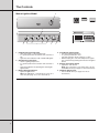
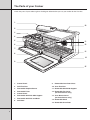
GAS ELEVATED COOKERS
Contents
General safety warnings
Cooking symbols
The controls
The parts of your cooker
3
3
4
6
Using the oven
Baking
Lighting the oven
Preheating the oven
Fan baking
Oven safety warnings
Oven cooking guide
Handling baking problems
Using the grill
Grilling
Lighting the grill
Grill safety warnings
Handling grilling problems
Using hotplate burners
Manual ignition burners
Electronic ignition burners
Hotplate safety warnings
7
7
7
7
8
8
9
10
11
11
11
11
11
12
12
12
12
Using the timer and clock
Using the 60 minute ringer timer
Using the electronic clock
Setting the timer
Cleaning the cooker
Safety warnings about cleaning
Cleaning the enamel
Cleaning the control panel
Cleaning the cooktop
Cleaning the grill compartment
Cleaning the oven door
Cleaning the oven compartment
Solving problems
Installing the cooker
Safety warnings about installation
Locating the cooker
Checking gas pressures
Checking pipe size
Gas connection
Testing the operation of the cooker
Checking gas supply
Natural gas
Testing the cooker features
13
13
13
13
14
14
14
14
14
15
16
17
18
19
19
19
20
20
21
22
22
22
23
Warranties
New Zealand warranty
Australian warranty
24
24
2
General Safety Warnings
•
•
•
•
•
•
•
•
DO NOT allow young children to use the gas cooker.
DO NOT touch surfaces when they are hot.
DO NOT use the cooker as a heater.
DO NOT spray aerosols near the cooker.
DO NOT store flammable materials in or under the cooker.
ALWAYS stay with children and infirm people when they use the cooker.
ALWAYS keep vents clear to avoid fires.
ALWAYS keep the cooker clean to avoid fires.
Cooking Guide Symbols
In this booklet you will see the following symbols which will help you follow the
instructions more easily.
Hotplate burners
Grilling
Fan baking
Baking
e
. You ar
n
io
is
c
e
d
’s
de a wise one of Australia
a
m
e
v
a
er of
You h
roud own e appliances.
p
e
h
t
w
m
no
your
finest ho
you use
e
r
fo
e
b
e
y
t carefull . By following th e
le
k
o
o
b
Read this for the first time t you will get th
cooker s in this bookle ker and save
n
oo
instructio ults from your c ervice calls.
best res unnecessary s
y for
yourself
let hand
k
o
o
b
is
Keep th re reference.
futu
3
The Controls
Manual Ignition Model
6
2
3
1
4
1. Hotplate Burner Control Knob
• Sets the hotplate cooking temperature.
• To operate push knob in and turn anti-clockwise to
“Hi”.
• Ignite the selected burner with a hand held igniter.
2. Grill Burner Control Knob
• Sets the grilling temperature.
• To operate push knob in and turn anti-clockwise to
“Hi”.
• Ignite the grill burner by pushing the manual grill
igniter button.
3. Manual Grill Igniter Button
• Ignites the grill burner.
Note: The grill burner control knob has to be set to
max. first (see page 11 for more information).
4
5
4. Oven Burner Control Knob
• Sets the baking temperature.
• To operate push knob in and
turn anti-clockwise about a quarter of a turn.
• While keeping the control knob depressed, ignite
the oven burner by pushing the manual oven igniter
button.
5. Manual Oven Igniter Button
• Ignites the oven burner.
Note: The oven burner control knob has to be set
and held down first (see page 7 for more information).
6. 60 Minute Ringer Timer
• Sets reminder time (see page 13 for more
information.)
The Controls
Electronic Ignition Models
f a n
7
f o r c e d
2
6
5
4
1
3
1. Hotplate Burner Control Knob
• Sets the hotplate cooking temperature.
• To operate, push knob in and turn anti-clockwise to “Hi”.
• Ignite the selected burner by pushing the electronic igniter
switch.
2. Grill Burner Control Knob
• Sets the grilling temperature.
• To operate, push knob in and turn anti-clockwise to “Hi”.
• Ignite the grill burner by pushing the electronic igniter
switch.
3. Oven Burner Control Knob
• Sets the baking temperature.
• To operate, push knob in and turn anti-clockwise about a
quarter of a turn.
• While keeping the control knob depressed, ignite the oven
burner by pushing the electronic igniter switch.
4. Electronic Igniter Switch
• Ignites the hotplate burners, grill burner and oven burner.
Note: The appropriate burner control knob has to be set
first.
5. Fan Switch
• Turns oven fan on/off.
6. Light Switch
• Turns oven fan on/off.
7. Electronic Clock
• Shows the time of day.
• Sets baking/grilling reminder time.
(See page 13 for more information).
5
The Parts of your Cooker
Check the parts of your cooker against the diagram below before you use your cooker for the first time.
1.
10.
2.
3.
4.
5.
11.
6.
12.
7.
13.
8.
14.
9.
15.
6
1.
Control Panel
9.
Removable Inner Door Glass
2.
Grill Flue Vent
10. Oven Flue Vent
3.
Removable Hotplate Burner
11. Removable Shelf Side Support
4.
Removable Trivet
5.
Control Panel
12. Removable Fan Cover
(fan forced ovens only)
6.
Removable Grill Dish Side Support
7.
Removable Grill Dish and Rack
8.
Grill Door
13. Oven Burner Cover
(fan forced ovens only)
14. Removable Shelf
15. Removable Oven Door
Using the Oven
Baking
•
With conventional oven models heat comes from the burner
below the food (see diagram opposite).
•
The burner is controlled by the thermostat which sets the
oven temperature.
•
There is a variation in temperature between the bottom and
the top of the oven. The bottom shelf is the coolest and the
top shelf is the hottest.
Lighting the oven
1. Press the oven burner control knob and turn it a quarter of the way.
For manual ignition models
2. Keep the oven burner control knob pushed in and at the same time press the oven igniter button
on the right hand side of the control panel.
For electronic ignition models
2. Keep the oven burner control knob pushed in and at the same time press the electronic igniter
switch on the right hand side of the control panel.
3. Hold the control knob for about 20 seconds when the burner lights, before releasing it.
From a cold start the oven burner flame will look
similar to the diagram opposite
NOTE: If the oven does not light within 10 seconds, or the flame goes out after you release the
oven burner control knob, follow these steps:
1. Turn the oven burner control knob back to the start position and let go.
2. Open the oven door to stop gas building up.
3. Wait one minute and repeat the steps to light the oven.
Preheating the oven
We recommend that you preheat your oven before you put the food in to be cooked.
The following table tells you how long it takes to preheat a cold oven to different temperatures.
Set temperature
Heating time
150°C
5 minutes
200°C
8 minutes
250°C
12 minutes
7
Using the Oven
Fan Baking (Fan forced oven models)
•
With fan forced ovens, heat comes from burner below the
food (see diagram opposite).
•
The fan circulates the hot air and so the temperature is more
even throughout the oven.
•
Fan baking:
– cooks faster and at lower temperatures than
conventional baking
– is good when you are cooking food on different shelves
at the the same time.
NOTE: WE recommend that you preheat your oven before you turn the fan on.
Oven Safety Warnings
8
•
ALWAYS follow the instructions for putting the shelves and fittings into the oven, to avoid
accidents.
•
DO NOT line the oven with foil.
•
DO NOT use polyunsaturated oil when cooking in the oven. This type of oil can cause heavy
deposits inside the oven.
•
DO NOT touch the hot surfaces inside the oven.
•
DO NOT use the oven door as a shelf.
•
DO NOT push down on the open oven door.
Oven Cooking Guide
The following is intended as a guide and experience may show some slight variation to be necessary to meet individual
requirements.
FOOD
Scones
Plain or Fruit
Biscuits
Rolled
Spooned
Shortbread Biscuits
Macaroons
Meringues
Hard - Individual
Soft - Individual
Pavlova - 6 egg
Cakes
Patty Cakes
Sponge - 4 egg
Plain Butter Cake
Nut Loaf
Boiled Fruit Cake
Rich Fruit Cake
Pastry - Shortcrust
Cornish Pasties
Custard Tart
Steak & Kidney Pie
Pastry Choux
Cream Puffs
Yeast Goods
Buns
Bread
Puddings
Chocolate
Cheese Souffle - 4 egg
TEMPERATURE & TIME
CONVENTIONAL OVEN
TEMPERATURE & TIME
FAN FORCED OVEN
230°C//10 - 12 MINS
210°C//10 - 12 MINS
180°C//10 - 15 MINS
190°C//10 - 15 MINS
170°C//20 - 25 MINS
160°C//20 - 30 MINS
170 - 180°C//10 - 15 MINS
170 - 180°C//10 - 15 MINS
150°C//15 - 20 MINS
140°C//15 - 20 MINS
100°C//1 - 11/2 HOURS
190 - 200°C//30 MINS
120°C//11/2 - 13/4 HOURS
80 - 100°C//1 - 11/2 HOURS
180°C//30 - 45 MINS
110 - 120°C//1 - 11/2 HOURS
190 - 200°C//15 - 20 MINS
190°C//18 - 20 MINS
180°C//50 -70 MINS
180°C//45 - 50 MINS
180°C//1 - 11/2 HOURS
140°C//31/2 - 41/2 HOURS
190 - 200°C//15 - 20 MINS
170 - 180°C//18 - 20 MINS
170 - 180°C//50 - 60 MINS
170°C//45 - 50 MINS
160 - 170°C//1 - 11/2 HOURS
140°C//3 -31/2 HOURS
220°C//10 MINS THEN 180°C//20 - 30 MINS
200°C//10 MINS THEN 180°C//25 - 30 MINS
220°C//15 MINS THEN 190°C//15 - 20 MINS
200°C//10 MINS THEN 180°C//30 MINS
200°C//10 MINS THEN 160°C//30 MINS
210°C//15 MINS THEN 180°C//30 - 40 MINS
220°C//20 MINS THEN 200°C//30 MINS
220°C//10 MINS THEN 180°C//30 MINS
220°C//20 - 30 MINS
220°C//25 - 35 MINS
200°C//20 - 30 MINS
190°C//25 - 30 MINS
180°C//40 - 50 MINS
190 - 200°C//40 - 50 MINS
170°C//40 MINS
180°C//35 MINS
MEAT
Beef
PREFERRED TEMPS
200°C
Lamb
200°C
Veal
Pork
180°C
200°C
Rare
Medium
Well Done
Medium
Well Done
Well Done
Well Done
POULTRY OR FISH
Chicken
Duck
Turkey
PREFERRED TEMP
180°C
180 - 200°C
180°C
Fish
180°C
MINUTES PER KG
35 - 40 minutes
45 - 50 minutes
55 - 60 minutes
40 minutes
60 minutes
60 minutes
60 minutes
MINUTES PER KG
40 - 45 minutes
60 - 70 minutes
35 - 40 minutes (less than 10kg)
40 - 45 minutes (more than 10 kg)
20 minutes
9
Handling Baking Problems
Problem
Causes
What to do
Uneven cooking
•
Incorrect shelf position
•
Select shelf which puts food in
centre of oven
•
Oven tray too large
•
Try other trays or dishes
•
Trays not in centre of oven
•
Put trays in centre of oven
•
Air flow in oven uneven
•
Turn food during cooking
•
Oven not preheated
•
Preheat until indicator light goes
off
•
Aluminium foil in oven
•
Remove foil
•
Baking tins too large for recipe
•
Use correct size tins
•
Baking tins not evenly spaced
•
Place baking tins so that there is
at least 3 cms between tins and
oven walls
•
Food not evenly sized or placed
on trays
•
Make food same size and shape
and spread evenly on trays
•
Food placed too close to top of
oven
•
Place food in middle or on a
lower shelf
Baked products too
•
Baking temperature too high
•
Lower temperature
brown on bottom
•
Baking tins too large for recipe
•
Use correct size tins
•
Baking tins are dark metal or
glass
•
Change to shiny, light tins or
lower temperature by 10°C
•
Food too low in oven
•
Cook one shelf higher
•
Oven door opened to
frequently during cooking
•
Do not open door until half way
through cooking time
Cakes have cracked
•
Baking temperature too high
•
Lower temperature
thick crust
•
Food too high in oven
•
Cook one shelf lower
•
Cake batter overmixed
•
Mix just long enough to
combine ingredients
•
Pan too deep
•
Check size of pan and use
recommended size
•
Baking tins too dark
•
Change to shiny tins
Baking products are
•
Baking temperature too low
•
Raise temperature
pale, flat and
•
Food too low in oven
•
Cook one shelf higher
undercooked
•
Baking time too short
•
Increase cooking time
Baked products too
brown on top
•
Incorrect tin size
•
Use correct size tin
Cakes fallen in
•
Baking temperature too low
•
Raise temperature
centre
•
Baking time too short
•
Increase cooking time
•
Measurement of ingredients is
wrong
•
Check recipe
•
Door opened too early
•
Do not open door until three quarters
(3/4) of way through cooking time
Crusts too thick
•
Incorrect ingredients
•
Check recipe
Meat and potatoes not
browning in fan oven
•
Poor circulation
•
Put food onto a rack to allow air
to circulate
•
Do not pierce meat with fork but
turn with tongs
Juices running out of
meat
NOTE: Condensation on oven door is normal.
10
Using the Grill
Grilling
•
The grill works by directing heat onto the food.
(see diagram opposite).
•
The grill is suitable for tender cuts of meat, steak chops,
sausages, fish, toasted cheese and other foods which cook quickly.
Lighting the grill
NOTE: Before you cook on the grill for the first time, turn the grill on for fifteen minutes
with 10 mm of water in the bottom of the grill dish. This will remove
oils left on the grill during manufacture.
1. Press the grill burner control knob and turn it all the way.
For manual ignition models
2. Press the manual igniter button on the left hand side of the control panel.
For electronic ignition models
2. Press the electronic igniter switch on the right hand side of the panel.
NOTE: If the grill does not light after 8 seconds, follow these steps:
1. Turn the grill burner control knob back to the start position and let go.
2. Wait 15 seconds for the gas to clear and repeat the steps to light the grill.
NOTE: For best results the grill should be preheated for 3 minutes before cooking to seal the natural
juices of meat.
The grill door MUST be left open during grilling.
Grill Safety Warnings
•
ALWAYS turn the grill off immediately after you have finished cooking. Fat left in the grill can catch fire.
•
ALWAYS leave the grill door open during grilling.
•
ALWAYS make sure that grill trays are fitted into the grill according to instructions.
•
DO NOT line the chrome grill rack with foil.
•
DO NOT leave the grill unattended.
•
DO NOT touch the hot surfaces inside the grill and keep children away until the grill has cooled.
•
DO NOT place thick pieces of food under the grill. Food may catch fire.
•
DO NOT store flammable materials near the grill.
Handling grilling problems
Problem
Causes
What to do
Grilled meats
overcooked on outside
and raw in centre
•
Meat too close to grill
•
Excess grill smoke
•
Build-up of fats in grill
Grill at lower shelf position
•
Clean grill
Juices running out of
meat
•
Do not pierce meat with fork but
turn with tongs
Grilled steaks and
chops buckling
•
Cut fat with knife towards meat
NOTE: Condensation in grill compartment is normal.
11
Using Hotplate Burners
Check the hotplates on your cooker against the diagram below before you use your cooker for the first time.
NOTE: To save gas, place pots and pans centrally over the burners and adjust gas so that flames do not go
past edges.
What it is
What it is used for
1
Low heat burner
5.1mj/h
• Used for simmering
• Used with small pots and pans
2&3
Medium heat burners
9.0mj/h
• Used for normal cooking
• Used with middle size pots & pans
4
High heat burner
12.4mj/h
• Used for fast heating
• Used with large size pots & pans
Manual ignition Models
1
2
4
3
To light these hotplates:
1. Choose the hotplate you want to use.
2. Turn the hotplate burner control knob to “Hi”.
3. Light with a hand held lighter eg match.
Electronic ignition Models
To light these hotplates:
1. Choose the hotplate you want to use.
2. Turn the hotplate burner control knob to “Hi”.
3. Press electronic igniter switch to release sparks to the burner.
Hotplate Safety Warnings
12
•
ALWAYS make sure that burner caps are in right positions.
•
DO NOT leave the hotplate on with no pot or pan on the hotplate.
•
DO NOT use asbestos mats or heat diffusers. These will cause a temperature build-up which can damage
the enamel.
•
DO NOT let large pots or pans overhang the cooktop. This may scorch the benchtops next to the cooker.
•
DO NOT let pots or pans boil dry. This can damage the enamel on the cooktop.
•
DO NOT let cooking utensils get too close to the hotplate control knobs.
Using the Timer and Clock
Using the 60 minute ringer timer
To set the timer:
1.
Turn the knob to the required number of minutes
(see diagram opposite).
NB: For times below 15 minutes, turn the knob past
fifteen and then turn back to the number of minutes.
When timer returns to zero, the timer gives a short
ring.
Using the electronic clock
The clock has a 24 hour display. When you turn the oven on
for the first time, 0.00 will show on display.
To set the clock:
1.
Press ▲ and ▼ buttons (see diagram opposite) at
the same time.
2.
Release and then push ▲ or ▼ until the correct time
is displayed.
3.
Wait 4 seconds.
If the timer symbol
is not displayed, then the time is set.
If the timer symbol is displayed, then you have accidentally
set the countdown timer. To correct this, you need to reset
the timer to 0.00 (see below) and start again from Step 1.
Setting the timer
To set the timer:
1.
Press ▲ and ▼ buttons (see diagram opposite) to
start the minute timer. The timer symbol
will show on
the screen.
2.
Press ▲ button to increase the time.
3.
After setting the timer, wait 4 seconds and
the time of day will be displayed again.
4.
To view the remaining time press the
▲ or ▼ button.
5.
The timer will now count to zero (0) and
a buzzer will sound for 2 mins.
6.
Press the ▲ or ▼ button to stop the buzzer
wait 4 seconds. The time will reappear.
Timer Symbol
To reset the timer (and display time):
1.
Press the ▼ button until you see zero on the display.
2.
Wait 4 seconds and the time will reappear.
13
Cleaning the Cooker
Safety Warnings about cleaning
•
ALWAYS make sure that the cooker is turned off before cleaning.
•
ALWAYS clean cooker immediately after use.
•
DO NOT use steam cleaners. These may cause moisture build-up.
•
DO NOT use caustic based cleaners. These will damage aluminium parts.
Cleaning the enamel:
•
•
•
•
Cleaning the control panel: •
•
•
Keep enamel clean by wiping it with a soft cloth dipped in warm soapy
water.
Rub difficult stains with a nylon scourer or creamed cleanser.
DO NOT use abrasive cleaners, powder cleaners, steel wool or wax
polishes.
If you use an oven cleaner, follow the instructions on the product carefully.
Make sure control knobs are in OFF position.
Remove knobs from control panel by pulling towards you.
DO NOT use too much water when cleaning control panel.
Cleaning the cooktop
1. Remove the trivets (see diagram opposite) by lifting
them from hob.
2. Remove the burner caps and crowns (see diagram
opposite).
3. Wash hob with warm soapy water.
4. If crowns and caps are heavily soiled use a non-abrasive
cleaning compound.
DO NOT use abrasive or caustic based cleaners.
DO NOT wash in a dishwasher.
NOTE:
DO NOT drop trivet onto hob. This may damage
the enamel surface.
Refitting the burner crowns and caps
The burner crown must be fitted correctly into
the burner cup or damage will occur during
operation.
Spark Plug Hole
Burner Crown
To do this ensure that the 2 ribs on either
side of the spark plug hole are positioned
into the 2 slots on the burner cup.
(see diagram opposite)
The burner cap is simply positioned
over the top of the burner crown.
Flame port
Burner cup
14
Cleaning the Cooker
Cleaning the grill compartment
NOTE: You can use household enamel cleaners but you
MUST follow the instructions on the product.
DO NOT use a harsh abrasive cleaner, powder
cleaners, steel wool or wax polishes.
Removing the grill dish
1. Pull the grill dish forwards and upward.
2. Clean both the grill and grill rack in hot soapy water.
Heavy baked-on stains may require soaking.
3. When replacing the grill dish make sure that the rear
of the dish is fitted onto side supports before sliding
backwards.
Removing the grill dish supports
The grill dish supports can be removed for easy
cleaning of the grill compartment.
1. Hold the grill dish supports at the front and pull
them inwards (see diagram opposite).
2. Clean the grill compartment with warm soapy
water or use a non-abrasive oven cleaner with
a nylon scourer for hard to clean areas.
3. Replace the grill dish supports by inserting the
rear hook into the rear hole.
4. Place front peg into front hole and push in firmly
(see diagram opposite).
15
Cleaning the Cooker
Cleaning the Oven Door
Removing the oven door
The oven door can be removed for easy cleaning.
1. Open the door fully.
2. Turn the two stirrups forward so that they fit with the
hooks on the hinge arms (see diagram opposite). Hold
the stirrups in place and slightly close the oven door.
The stirrups will now remain fitted.
3. Close the door halfway and lift it away from the oven.
Replacing the oven door
1. Relocate both hinge arms at the same time into the
oven front housing.
2. Make sure that the location notches on the bottom of
the hinge arms are positioned onto the lower cut-out
lip. (see diagram opposite).
3. Close the door part of the way to make sure that the
location notch drops into place.
4. When the hinges are located, open the door fully making
sure the stirrups are not fitted.
AIRWASH DOOR
The door on your cooker is designed to allow cool air to
pass up through the middle and out through the vent in
the top of the door.
(see diagram opposite)
This feature results in lower surface temperatures on the
outside of the door.
Cleaning the door glass
To help with cleaning the door your cooker has a removable
inner door glass.
1. First remove the oven door from the cooker and
lie it down flat (refer to instructions above)
2. Undo the screws on either side of the door and
remove the 2 glass retaining plates and rubber
pads.
3. Remove the inner glass and clean in hot soapy
water.
4. The inside of the outer glass can also be wiped
clean.
5. When reassembling do not overtighten the retaining
plate screw.
WARNING:
NEVER lift or carry the oven door by the handle.
DO NOT put the door in water.
DO NOT use force to replace the door.
ALWAYS make sure that the location notch is correctly
fitted before closing the door.
DO NOT remove the inner door glass while the door is still
on the cooker.
DO NOT use the oven without the inner door glass fitted.
16
Cleaning the Cooker
Cleaning the Oven Compartment
Removing the oven shelves
1. Slide the oven shelves towards you until they reach the
front stop.
2. Tilt them up at the front to clear the side supports and
lift them clear (see diagram opposite).
3. Wash the shelves in warm soapy water or soak the
shelves to remove heavy stains.
Removing the oven shelf supports
1. Grasp the shelf supports at the front.
2. Pull them inwards (see diagram opposite).
3. Wash the shelf supports in warm soapy water or
soak the supports to remove heavy stains.
4. Replace the shelf supports by inserting the rear
hook into the rear hole.
5. Place front pegs into front hole and push in firmly
(see diagram opposite).
Removing the fan cover (Fan forced models only)
1. Make sure that the cooker is turned off.
2. Hold the fan cover on both sides and pull firmly towards
you (see diagram opposite).
3. Wash the fan cover in warm soapy water or soak the
cover to remove heavy stains.
4. Replace the fan cover by inserting the two tabs at the
bottom of the fan cover into the corresponding holes.
5. Push the top of the fan cover into place.
Removing the oven light glass (Fan forced models only)
1. Make sure that the cooker is turned off.
2. Turn the oven light glass anti-clockwise (see diagram
opposite).
NOTE: The oven burner cover (Fan forced models only)
and oven burner are not removable for cleaning.
Accidental spills should be cleaned immediately
so that the burner does not become blocked.
17
Solving Problems
If you have a problem with the oven or the grill, check the table below. You may be able to solve the problem
and this will save you from paying for a service call. You will have to pay for a service call even in the warranty
period if the problem is one listed in the table.
NOTE:
Only an authorised technician should carry out servicing.
When you need information about your cooker, a service or replacement parts look at the data plate
which you can see when the oven door is open. Tell the service agent the Model Number and the
Serial Number.
Problem
Possible causes
What to do
No spark obtained
when electronic
igniter is pressed
(Fan Forced Models only)
•
•
•
•
Power not turned on
Household fuse blown
Circuit breaker tripped
Spark plug is wet or dirty
•
•
•
Switch on electricity
Check fuses
Check circuit breaker
No spark obtained
•
when manual igniter
is pressed
(Manual Ignition Models only)
Spark plug is wet or dirty
•
Dry or clean spark plug
Burner will not
light even though
igniter is working
•
•
Gas supply valve is turned off
Port blockage in ignition area
•
•
Turn on gas supply
Make sure that ports and
ignition area are clean and dry
Oven light not
working
(Fan Forced Models only)
•
•
•
•
Power not turned on
Household fuse blown
Circuit breaker tripped
Lamp blown or loose in socket
•
•
•
•
Switch on electricity
Check fuses
Check circuit breaker
Replace or tighten globe
Electronic clock
flashing
(Fan Forced Models only)
•
Power failure or interruption
•
Reset time of day
Oven cooking time
is too long
•
•
•
Heat escaping through
incorrectly sealed door
The set oven temperature is incorrect
•
Check oven door is properly
closed
Change set oven temperature
Cooker smoking
when first used
•
Protective oils being removed
•
Turn grill or oven on high for
10 mins
Too much
condensation
building up when
baking
•
Too much water used when
cooking
•
•
Reduce amount of water
Leave door open after cooking,
if food is left in oven to keep
warm
•
This is normal
Smells when first
using oven
18
Installing the Cooker
Safety warnings about installation
• The cooker MUST be installed and serviced by a qualified technician.
• A Certificate of Compliance MUST be supplied to be kept by the customer.
• The packing materials MUST be removed before you install the cooker.
• You MUST follow the installation instructions in this booklet.
• The surrounding kitchen cabinets MUST be able to withstand 85°C.
Electrolux Products WILL NOT accept responsibility for damage caused by installation into kitchen cabinets
which cannot withstand 85°C.
• The appliance MUST be installed using the flexible hose supplied.
• The vents, openings and air spaces MUST not be blocked or covered.
• You MUST not pull the cooker by the door handles or the splashback.
• The cooker MUST be checked every five years.
Locating the cooker
Study the diagrams below to be sure of the dimensions required to locate the cooker safely.
NOTE: Make sure that the top of the hotplate surface is at least 10 mm higher than the level of the benchtops.
IMPORTANT: Before you cook in your new oven it is important that the protective oils used in the manufacture of the
product be removed.
• Make sure that the room is well ventilated (to allow smoke to escape).
• Run the grill on high for 15 minutes.
• Then run the oven on 220° for 4-8 hours.
19
Installing the Cooker
Checking gas pressures
The cooker MUST be installed in compliance with:
•
the Installation Code for Gas Burning Appliances and Equipment - AS 5601/ AG 601 - issued
by standards Australia (Particular reference to sections 4.8 & 5.12.1).
•
local gas fitting regulations, municipal building codes and other statutory regulations.
The cookers come in two gas types: Natural gas and Propane. Before installation check that the
cooker is suitable for the gas supply. To do this check the gas type on the carton sticker or on the
data plate behind the bottom of the oven door.
The following table shows the supply and operating pressures for various gas supplies.
GAS TYPE
SUPPLY PRESSURE
at inlet to appliance regulator (if fitted)
NATURAL GAS
PROPANE
1.13 (kPa) Minimum
2.75* (kPa)
1.00 (kPa)
2.75 (kPa)
OPERATING PRESSURE
at appliance test point
* If the regulator is placed upstream of the cooker inlet, as is normal for cookers operating on
Propane, then the supply pressure and operating pressure are the same.
The following table shows the injector sizes for each burner.
INJECTOR ORIFICE
NATURAL GAS
PROPANE
LOW HEAT BURNER
1.00 mm
0.62 mm
MEDIUM HEAT BURNER
1.35 mm
0.82 mm
HIGH HEAT BURNER
1.60 mm
0.95 mm
INTENSE HEAT WOK BURNER
1.80 mm
1.05 mm
GRILL - main injector
1.50 mm
0.82 mm
NA
NA
OVEN - main injector
1.60 mm
0.95 mm
OVEN - bypass screw
0.70 mm
0.40 mm
NATURAL GAS
PROPANE
62 MJ
59 MJ
GRILL - bypass screw where fitted
Checking pipe size
To work out a suitable pipe size for connection use:
•
the information in this table.
GAS TYPE
Hourly gas consumption for this
cooker
•
information about the length of the run, number of elbows, tees and bends, the available service
pressure and the supply requirements.
NOTE: The Code AS 5601 /AG 601 will help you with this matter
20
Installing the Cooker
Gas connection
Read these points before connecting to the gas supply:
• The cooker inlet connection point is the inlet to the regulator or LP test point adaptor. This connects to the
flexible hose fitted to the appliance. The appliance must be installed using the hose supplied.
Operation on NG/SNG
Read these points about operation on NG/SNG and look carefully at the diagram:
•
•
•
•
The appliance regulator which is provided MUST
be fitted and positioned so that the pressure nipple
and adjuster screw are accessible.
The arrow showing the direction of the flow MUST
be pointed correctly.
Connect the gas supply to the 1/2” BSP internal
thread inlet of the regulator.
The flat fibre washer which is provided in the
regulator parts MUST be used when making the
gas connection.
Washer
(P/No. 115-009-011)
Internal
Flange
NG Regulator
(P/No. 294-001-026)
w
Gas Flo
Operation on SNG
• If the cooker is to be used with SNG, then the grill burner MUST be modified by the replacement of the
shutter which fits into the throat of the grill burner.
• You can buy the kit for this modification from your nearest spare parts stocklist.
1. Remove the control panel. Remove the existing NG shutter and fit the shutter in the throat of the grill burner.
2. Align the hole in the shutter with the hole in the grill burner and secure the short screw.
Operation on Propane
An inlet fitting with pressure test point is provided. Orient the fitting so that gas flows in the direction of the
arrow marked on the fitting. Use the sealing washer to connect the fitting to the flexible hose. Connect the gas
supply to the 1/2” BSP internal thread inlet of the fitting.
21
Testing the Operation of the Cooker
NOTE: You MUST test the cooker after installation, before you hand it over to the customer.
You MUST have a manometer and a connecting tube.
Checking gas supply
1. Check the manometer zero point is correct.
2. Connect the manometer to the cooker pressure test point. This is located on the regulator or LPG inlet
fitting behind the kick panel under the storage drawer.
3. Turn on the gas supply and the electricity (if applicable) and try to ignite the gas.
NOTE: It will take additional time to light the gas for the first time as air needs to be
purged from the pipes.
4. Check the operating pressure and adjust the regulator to the appropriate setting for the particular gas type
(see table on page 25).
NOTE: For LPG cookers the regulator may be remote from the cooker.
Natural gas
1. Turn on smallest burner to minimum.
2. Adjust screw fully in and read pressure.
3. If reading is below 1.13 kPa, then supply pressure is not enough.
If supply pressure is between 1.13 kPa and 1.20 kPa, then follow these instructions:
1. Turn the adjusting screw outward until the pressure just begins to drop. Carefully adjust to a pressure of
1.10kPa.
NOTE: The screw may unwind fully before the pressure drops. If this happens, then remove the screw and
let the pressure fall. Then reinsert the screw and finish the adjustment.
2. Turn the control for the small burner slightly away from the minimum until the pressure drops and then
slowly turn back to minimum.
3. Repeat steps 1 and 2 until the pressure always returns to 1.10 kPa.
4. Turn all burners to maximum and read the pressure. If it is below 0.82 kPa, then repeat steps 1 to 4.
5. Lock the nut.
22
Testing the Operation of the Cooker
If supply pressure is above 1.20 kPa, then follow these instructions:
1. Turn all the burners to maximum.
2. Adjust the screw so that the test point pressure reads 0.85 kPa and tighten the nut slightly.
3. Turn the smallest burner to minimum and turn all the other burners off. Gently tap the regulator until
test point pressure is stable and read pressure.
4. Turn all the burners to maximum and read pressure. Evaluate the difference between this reading
and the one you read in Step 3.
5. Adjust the screw so that the difference between this reading and 1.0 kPa is about half the difference
between the two readings found in Steps 3 and 4.
6. Repeat Steps 3 to 5 until no further adjustment is needed.
NOTE: The 1.0 kPa should now be about halfway between the reading with all the burners on at maximum
and the reading when the small burner is on minimum (see diagram below).
–
–
1.2 kPa —
1.2 kPa —
–
–
1.1 kPa —
1.1 kPa —
–
1.0 kPa —
–
0.9 kPa —
1.0 kPa lies
halfway between
these two readings
–
1.0 kPa —
–
0.9 kPa —
–
–
0.8 kPa —
0.8 kPa —
–
–
Test Point Pressure with all
burners operating at maximum.
Test Point Pressure with small
burner operating at minimum.
7. Lock the nut.
Testing the cooker features
•
Observe the flame appearance on each burner. If it is much larger or smaller than expected, then the
injector size needs checking.
NOTE: When flame is unsatisfactory, then refer to the Electrolux Technical
Publications and correct the fault, if possible.
When the maximum flame appearance is correct, then check the turn-down setting on each burner. If
the settings appear to be incorrect, proceed as follows:
1. Adjust the bypass screw on each hotplate control cock. This is accessible when the control knob is
removed. Use a thin flat screwdriver inserted through a hole in the centre of the control cock spindle.
NOTE: If the hotplate control cock does not have a hole in the centre of the control cock spindle, then
remove the control panel and adjust the bypass screw mounted on the body of the hotplate control
cock.
2. Check the ignition on all burners both separately and in combination.
3. Check the operation of the electrical components, if applicable.
4. If you are satisfied that the cooker is operating correctly, then turn it off and show the customer how
to use it. Make sure you ask the customer to operate the clock and the controls.
NOTE: If the cooker cannot be adjusted to perform correctly, then inform the customer of the problem
and put a warning notice on the cooker. If the problem is dangerous, then disconnect the cooker.
If there is a fault, then the customer should be advised to contact the manufacturer’s local service
organisation or the retailer.
23
P/N 342-1-504 ECN 03A134A 2/04
The Company or its Authorised Service Centre will pay the cost of repairing or replacing all parts
of the appliance which the Company or its Authorised Service Centre find defective for a period
of 24 months following the date of purchase (the ‘\/Varranty Period”).
During the Warranty Period the Company or its Authorised Service Centre, will pay the cost of
repairing or replacing all parts which they find are defective.
Light globes, batteries and filters are replaceable parts and are not covered under this warranty.
The appliance must be installed and operated in accordance with the Company’s instructions.
This Warranty does not apply to normal wear and tear, or any service which is needed after an
accident, negligence, alteration or misuse.
This Warranty also does not apply to damage caused if your appliance has been dismantled,
repaired or serviced by any person other than someone authorised by the Company.
If you live outside the service area of the Company or its Authorised Service Centre, this
warranty does not cover the cost of transport of the appliance for service nor the Authorised
Service Centre’s travelling costs to and from your home.
If you are required to transport the appliance to the Company or its Authorised Service Centre, it
must be securely packed and insured. The Company does not accept any responsibility for loss or
damage prior to it being received by the Company or its Authorised Service Centre.
This warranty is the only express warranty given by the Company.
This Warranty does not cover loss, damage or expense to this appliance caused directly or
indirectly by power surges, electrical storm damage or incorrect power current.
The Company (and any company related to the Company) will not be liable for any special
incidental or consequential damages or for loss, damage or expense directly or indirectly arising
from the use or inability to use this appliance, or for personal injury or loss or destruction of
other property.
Nothing in this warranty is intended to limit the rights you may have under the Consumer
Guarantees Act 1993, except to the extent permitted by that Act, and all provisions of this
warranty shall be read as modified to the extent necessary to give effect to that intention.
The Consumer Guarantees Act 1993 does not apply if your appliance is acquired for the purposes
of a “business” (as defined in that Act).
This warranty is limited to 90 days from date of purchase if the appliance is used for commercial
use.
For your nearest Authorised
Service Centre please look in
The Yellow Pages under
Home Appliance Servicing
OR
Call 0800 10 66 10
0800 10 66 10
PLEASE PHONE
SERVICE CENTRES
IMPORTANT NOTICE
Before calling a service technician please carefully check the warranty terms and conditions, the
operating instructions and service booklet if applicable. If the product fails for any of the customer
responsibility reasons detailed therein, a service fee will be charged. Please present proof of
purchase to any Authorised Service Centre should warranty service be required.
14
13
12
11
9
10
8
7
6
3
4
5
2
1
This appliance is warranted by Electrolux Home Products (NZ) Ltd (“the Company”) from the date of
purchase. The following terms and conditions apply:
ELECTROLUX APPLIANCE WARRANTY - NEW ZEALAND
FOR SERVICE IN AUSTRALIA
PLEASE CALL
13 13 49
FOR SPARE PARTS IN AUSTRALIA
PLEASE CALL
13 13 50
Conditions of the warranty:
1 During the Warranty Period the Company, or its service agent, will only pay the cost of repairing
or replacing all Company parts on your appliance which the Company finds to be defective.
2 The Company will decide if there are any defects in material and/or workmanship.
3 Light globes, batteries and filters are replaceable parts and are not covered under this warranty.
4 This warranty applies only for mainland Australia and Tasmania.
5 The appliance must be installed and operated in accordance with the Company’s instructions.
6 This warranty does not apply to normal wear and tear, or any service which is needed after an
accident, alteration, negligence, misuse, fire or flood.
7 This warranty does not apply to damage caused if your appliance has been dismantled, repaired
or serviced by any person other than someone authorised by the Company.
8 If you live outside the service area of the Company or one of its service agents, this warranty
does not cover the cost of transport of the appliance for service nor the service agent’s travelling
costs to and from your home.
9 If you are required to transport the appliance to the Company or its service agent, you must
ensure it is securely packed and insured. The Company does not accept any responsibility for loss
or damage of the appliance prior to it being received by the Company or its service agent.
10 This warranty does not cover loss, damage or expense to this appliance caused directly or
indirectly by power surges, electrical storm damage or incorrect power current.
11 The Company (and any company related to the Company) will not be liable for any special,
incidental or consequential damages or for loss, damage or expense or for personal injury or loss
or destruction of property arising directly or indirectly from the use or inability to use this
appliance or any of its parts.
12 This warranty applies only to the original buyer.
13 This warranty is the only express warranty given by the Company.
14 If you are the original buyer please keep your proof of purchase, which will be required if you
request service under this warranty.
15 The Warranty Period is only applicable when your appliance is used at home by you and your
family as consumers.
16 Use of this appliance for commercial purposes is covered by this warranty for a period of 3
months from the date of purchase.
Subject to the conditions below, this appliance is warranted by Electrolux Home Products Pty. Ltd.
A.B.N. 51 004 762 341, (the “Company”), to be free from defects in materials and workmanship for a
period of 24 months following the date of purchase (the “Warranty Period”).
Nothing in this warranty, limits any rights you may have under the Trade Practices Act or any other
Commonwealth or State legislation. Such rights cannot be changed by the conditions in this
warranty.
ELECTROLUX WARRANTY-AUSTRALIA