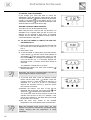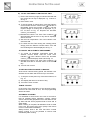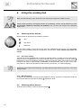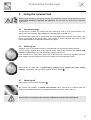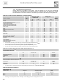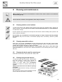
1
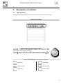
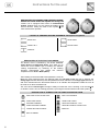
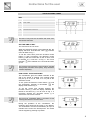
C41029G
C41029V
Range Cooker
User Instructions
PERFECT IN FORM AND FUNCTION
Thank you for choosing our product. From now on, cooking will always be
pleasantly creative with your new cooker.
We recommend carefully reading all the instructions in this manual, which
includes detailed information about the most suitable conditions for using the
cooker correctly and safely. These instructions also help you to become familiar
with each component.
Useful advice is given for using recipients, utensils, positions of guides and control
settings.
The correct cleaning operations contained in this manual allow you to maintain the
cooker's performance unchanged over time.
The individual sections are set out in order to allow you to become familiar with all
the functions in the cooker. The text is easy to comprehend and is accompanied
with detailed images and simple pictograms.
Reading this manual thoroughly will provide you with the answer to any question
that may arise regarding the correct use of your new cooker.
INSTRUCTIONS FOR THE USER: include suggestions, the description of the
controls and the correct cleaning and maintenance operations for the appliance.
INSTRUCTIONS FOR THE INSTALLER: for the qualified technician who is in
charge of adequately checking the gas system, installing, commissioning and
testing the appliance.
Contents
1. Warnings for safety and use ________________________________ 5
2. General information ______________________________________ 6
2.1
Technical service __________________________________________________________ 6
3. Description of controls_____________________________________ 7
3.1
The front panel ____________________________________________________________ 7
4. Using the cooking hob ___________________________________ 12
4.1
4.2
Switching on the burners ___________________________________________________ 12
Switching off the burners ___________________________________________________ 12
5. Using the ceramic hob ___________________________________ 13
5.1
5.2
5.3
General warnings _________________________________________________________ 13
Switching on_____________________________________________________________ 13
Switching off_____________________________________________________________ 13
6. Using the electric oven ___________________________________ 14
6.1
6.2
6.3
6.4
6.5
6.6
6.7
6.8
6.9
6.10
General warnings _________________________________________________________ 14
Switching on the oven for the first time ________________________________________ 14
Traditional cooking________________________________________________________ 14
Convection cooking _______________________________________________________ 14
Cooking with the ventilated grill ______________________________________________ 14
Cooking with the grill + spit _________________________________________________ 15
Cooking with the spit ______________________________________________________ 15
Defrosting_______________________________________________________________ 15
Switching off the oven _____________________________________________________ 15
Storage Drawer __________________________________________________________ 15
7. Cooking suggestions_____________________________________ 16
7.1
7.2
7.3
Suggestions for using the hob burners correctly _________________________________ 16
Suggestions for using the ceramic hob correctly _________________________________ 16
Suggestions for using the oven correctly_______________________________________ 16
8. Cleaning and maintenance ________________________________ 19
8.1
8.2
8.3
8.4
8.5
8.6
8.7
Cleaning stainless steel surfaces_____________________________________________ 19
Cleaning enamelled surfaces________________________________________________ 19
Cleaning the knobs and the control panel ______________________________________ 19
Cleaning the grids and burners ______________________________________________ 19
Cleaning the igniter plugs and thermocouples___________________________________ 20
Cleaning the ceramic hob __________________________________________________ 20
Cleaning the oven ________________________________________________________ 20
9. Special maintenance_____________________________________ 21
9.1
9.2
Removing the oven door ___________________________________________________ 21
Replacing the oven light bulb________________________________________________ 21
10. Service and Spare Parts _________________________________ 22
10.1 Customer Care___________________________________________________________ 22
3
Contents
11. Guarantee Conditions ___________________________________ 23
11.1 Standard guarantee conditions ______________________________________________ 23
11.2 Exclusions ______________________________________________________________ 23
11.3 European Guarantee ______________________________________________________ 23
12. Installation ____________________________________________ 24
12.1
12.2
12.3
12.4
12.5
12.6
12.7
12.8
General warnings _________________________________________________________ 24
Electric connection ________________________________________________________ 24
Power consumption of the ceramic hob________________________________________ 26
Ventilation requirements ___________________________________________________ 26
Gas connection __________________________________________________________ 27
Stability chain ____________________________________________________________ 28
Gas regulations __________________________________________________________ 29
Connecting to LPG________________________________________________________ 29
13. Final operations________________________________________ 30
13.1 Positioning and levelling the cooker __________________________________________ 30
CLASSES OF APPLIANCES
The cooking appliances described in this operating manual belong to the following installation
classes:
4
•
Class 1: non-flush-mounted cooking appliance;
•
Class 2 – subclass 1: cooking appliance flush-mounted between two
units, made up of a single unit, but which can also be installed so that the
side walls are accessible.
Warnings
1. Warnings for safety and use
THIS MANUAL IS AN INTEGRAL PART OF THE APPLIANCE. IT SHOULD BE KEPT IN GOOD CONDITION AND CLOSE
TO THE APPLIANCE FOR THE WHOLE LIFECYCLE OF THE COOKER. WE RECOMMEND READING THIS MANUAL
VERY CAREFULLY BEFORE USING THE COOKER. ALSO KEEP THE SET OF NOZZLES PROVIDED. THE
INSTALLATION MUST BE CARRIED OUT BY QUALIFIED PERSONNEL AND IN COMPLIANCE WITH CURRENT
STANDARDS. THIS APPLIANCE IS FOR DOMESTIC USE AND CONFORMS TO THE EEC DIRECTIVES CURRENTLY
IN FORCE. THE APPLIANCE IS BUILT FOR CARRYING OUT THE FOLLOWING FUNCTION: COOKING AND HEATING
FOOD; ANY OTHER USE IS TO BE CONSIDERED IMPROPER. THE MANUFACTURER DECLINES ANY
RESPONSIBILITY SHOULD THE APPLIANCE BE USED FOR PURPOSES OTHER THAN THOSE INDICATED.
DO NOT LEAVE ANY PIECES OF THE PACKING UNATTENDED IN THE HOME. SEPARATE THE VARIOUS PACKING
MATERIALS AND DELIVER THEM TO THE NEAREST RECYCLING CENTRE.
THE EARTH CONNECTION MUST CONFORM WITH THE RELEVANT IEE REGULATIONS IN FORCE.
THE PLUG TO BE CONNECTED TO THE POWER SUPPLY CABLE AND THE RELATIVE SOCKET MUST BE THE
SAME TYPE AND MUST COMPLY WITH CURRENT STANDARDS.
DO NOT PULL OUT THE PLUG BY PULLING THE CABLE.
SHOULD THE GAS TAPS BE DIFFICULT TO ROTATE, CONTACT YOUR LOCAL SERVICE FORCE CENTRE.
IMMEDIATELY AFTER INSTALLATION, TEST THE APPLIANCE BRIEFLY BY FOLLOWING THE INSTRUCTIONS
SHOWN BELOW. IN THE EVENT OF A MALFUNCTION, DISCONNECT THE APPLIANCE FROM THE MAINS AND
CONTACT YOUR NEAREST SERVICE FORCE CENTRE.
DO NOT ATTEMPT TO REPAIR THE APPLIANCE.
EACH TIME YOU FINISH USING THE COOKING HOB, ALWAYS CHECK THAT THE CONTROL KNOBS ARE IN "ZERO"
POSITION (OFF).
NEVER PUT INFLAMMABLE OBJECTS INTO THE OVEN: SHOULD IT BE ACCIDENTALLY SWITCHED ON, A FIRE
MAY BREAK OUT. IN THE EVENT OF A FIRE: TURN OFF THE MAIN GAS SUPPLY AND DISCONNECT FROM THE
MAINS SUPPLY. DO NOT THROW WATER ON BURNING OR FRYING OIL. DO NOT STORE INFLAMMABLE OBJECTS
OR AEROSOL CANS NEAR THE APPLIANCE AND DO NOT SPRAY NEAR THE BURNERS WHEN SWITCHED ON.
DO NOT USE SAUCEPANS THAT DO NOT HAVE A PERFECTLY SMOOTH, EVEN BASE ON THE HOB.
5
Warnings
DO NOT USE ANY PAN OR ACCESSORY THAT EXCEEDS THE OUTER PERIMETER OF THE HOB.
THE RATING PLATE WITH THE TECHNICAL DATA, SERIAL NUMBER AND THE BRAND IS CLEARLY VISIBLE ON THE
BACK OF THE APPLIANCE.
THE PLATE MUST NEVER BE REMOVED.
THE APPLIANCE SHOULD ONLY BE USED BY ADULTS. DO NOT ALLOW CHILDREN TO APPROACH OR PLAY
WITH THE APPLIANCE. DO NOT KEEP OBJECTS ON THE APPLIANCE THAT MAY ATTRACT CHILDREN'S
ATTENTION. KEEP CHILDREN AWAY FROM THE APPLIANCE; DO NOT FORGET THAT SOME PARTS OF THE
APPLIANCE OR THE PANS USED BECOME VERY HOT AND DANGEROUS DURING USE AND, AFTER SWITCHING
OFF, WHILE THE APPLIANCE IS COOLING. BE CAREFUL WITH PAN HANDLES: KEEP THEM TURNED INWARDS SO
THAT CHILDREN CANNOT OVERTURN THE PANS.
WHEN THE APPLIANCE IS DECOMMISSIONED, IT MUST BE DISPOSED OF IN A SUITABLE RECYCLING CENTRE.
The manufacturer declines any responsibility for damage incurred by persons or objects
that is caused by not following the above guidelines or by tampering with any part of the
appliance or by using non-original spare parts.
2. General information
This product conforms to the requirements of the following European directives:
•
•
•
•
73/23/EEC for "Low Voltage".
89/336/EEC for "Electromagnetic Disturbance".
90/396/EEC for "Gas Appliances".
89/109/EEC for "Material in contact with Food".
The above mentioned directives also conform to Machine directive 98/37/EC.
2.1
Technical service
Before leaving the factory, this appliance has been tested and set up by qualified, specialist
personnel, so as to guarantee the best operating results. Each repair or adjustment that may
subsequently be necessary must be carried out with the utmost care and attention. We therefore
recommend always contacting the Dealer where the appliance was purchased or your nearest
Service Centre, specifying the type of problem and the appliance model.
6
Instructions for the user
3. Description of controls
3.1
The front panel
All the commands and controls for the cooking hob and oven are on the front panel.
THE CONTROL PANEL
DESCRIPTION OF HOB CONTROL KNOB
The flame is ignited by simultaneously pressing and turning the knob
anticlockwise to the low flame symbol .
To regulate the size of the flame, turn the knob to between the maximum and
minimum settings. Turn off the burner by returning the knob to position .
LAYOUT OF BURNERS – Description of symbols
REAR LEFT
REAR RIGHT
CENTRE FRONT
CENTRE REAR
FRONT LEFT
FRONT RIGHT
7
Instructions for the user
DESCRIPTION OF CERAMIC HOB CONTROL KNOBS
Besides the normal knobs that regulate the energy, the
ceramic hob is equipped with knobs for differentiated
heating. Settings from 1 to 11 control the heating of the
internal element, setting the knob to the symbol
the
outer element also operates.
LAYOUT OF CERAMIC HEATING ELEMENTS - Description of symbols
REAR LEFT
REAR RIGHT
FRONT LEFT
FRONT RIGHT
CENTRAL
DESCRIPTION OF ELECTRIC OVEN KNOBS
The electric oven is controlled by two knobs: function
switch knob and thermostat knob. They allow you to
choose the most suitable type of heating for different
cooking requirements, by switching on the heating
elements appropriately and setting the required
temperature from 50°C to MAX (250°C).
The V setting on the thermostat knob operates the oven fan.
Below the oven knobs there are two warning lights: the red light signals the oven is working; the
orange light indicates that the preset temperature has been reached. The orange light switches on
and off to indicate when the thermostat switches on to maintain the temperature inside the oven at
the level set on the thermostat knob.
The oven has an internal light. The light is always on while the oven is working: it can be switched
on while the oven is off, for cleaning purposes, by turning the function switch knob to the symbol
DESCRIPTION OF SYMBOLS ON THE FUNCTION SWITCH KNOB
SWITCHES ON THE OVEN LIGHT
GRILL-FAN ELEMENT
UPPER AND LOWER
HEATING ELEMENTS
UPPER AND LOWER
HEATING ELEMENTS – FAN
UPPER HEATING ELEMENT
HEATING ELEMENT-CONVECTION
LOWER HEATING ELEMENT
DEFROST
GRILL ELEMENT
8
Instructions for the user
THE ELECTRONIC TIMER
KEY
A
COOK TIME
B
END TIME
C
COUNTDOWN
D
TIME
E
DECREASE CONTROL
F
SELECTOR CONTROL
G
INCREASE CONTROL
The time of day must be set before the main oven
will operate manually.
SET THE TIME OF DAY
The oven has a 24 hour clock.
When the electricity supply is first switched ON, the
display will show 12.00 and the 'Time' ( ) indicator
neon will flash as Fig. 1.
To set the correct time press the increase control
button (+) and if necessary, the decrease control
button (-) until the correct time on the 24 hour clock
is reached, e.g. 10.00 a.m. as Fig. 2. The 'Time'
indicator ( ) neon will flash for 5 seconds and then
go out.
The increase and decrease control buttons operate
slowly at first, and then more rapidly. They should be
pressed separately.
HOW TO SET THE COUNTDOWN
The 'Countdown' gives an audible reminder at the
end of any period of cooking. This cooking period
may be up to 2 hrs 30 mins. It is not part of the
automatic control.
To set, press the Selector Control button (
the 'Countdown' indicator is illuminated (
display reads 0.00 as Fig. 3.
) until
) the
To set the correct time duration depress the
increase control (+) until the display indicates the
interval to be timed, e.g. 1hr 45 mins as Fig. 4. If
necessary depress the decrease control (-) to
achieve the correct time interval.
This must be completed within 5 seconds of first
pressing the Selector Control button.
During the operation of the 'Countdown', the
remaining time period will be shown in the display.
The 'Countdown' will sound intermittently for up to 2
minutes at the end of the timed period. The sound
can be stopped by pressing any button.
9
Instructions for the user
TO CANCEL THE COUNTDOWN
If you change your mind and want to cancel the
'Countdown', press the Selector Control button until the
'Countdown' indicator ( ) flashes and then the decrease
control (-) until 0.00 shows in the display as Fig. 5. The
'Countdown' indicator ( ) will continue to flash for a few
seconds and then return to the time of day.
SETTING THE OVEN TIMER CONTROL
The main oven can be automatically timed.
When using the timer control for the very first time, it is
advisable to let it operate while you are at home. The
displays can be checked to show that it is operating
correctly and you will feel confident to leave a meal to
cook automatically in the future.
A) TO SET THE TIMER TO SWITCH ON AND OFF
AUTOMATICALLY
i) Ensure the electricity supply is switched ON and that
the correct time of day is displayed, e.g. 9 a.m. as
Fig. 6.
ii) Place food in oven.
iii) To set the length of cooking time, press the Selector
control button ( ) until the 'Cook Time' indicator is
illuminated ( ). Press the increase control (+) until
the required length of cooking time is displayed, e.g.
2 hrs 15 mins as Fig. 7. If necessary depress the
decrease control (-) until the correct time interval is
achieved.
The maximum cooking time is 10 hours.
iv) Release the buttons. The 'Cook Time' indicator (
will be illuminated.
)
Remember, this must be completed within 5 seconds of
first pressing the Selector Control button.
v) To set the 'End Time'. Press the Selector Control
button until the 'End Time' ( ) flashes. Press the
increase control (+) until the required stop time is
displayed, e.g. 12.15 p.m. as Fig. 8. If necessary
depress the decrease control (-) until the correct
time interval is achieved.
vi) Release the buttons. The time of day will be
displayed after 5 seconds. The 'Cook Time' ( ) and
'End Time' ( ) indicators will be illuminated.
The 'End Time' must not be more than 23 hours 59
minutes from the time of day. For example, if the
time of day is 09.00 a.m., the latest 'End Time' would
be 08.59 a.m. the next day.
vii) Set the main oven control to the required
temperature. The oven indicator neon should be OFF.
When the automatic timed period starts, the oven
indicator neon will turn ON and OFF periodically during
cooking, showing that the temperature is being
maintained.
10
Instructions for the user
B) TO SET THE TIMER TO SWITCH OFF ONLY
i) Ensure the electricity supply is switched ON and that
the correct time of day is displayed, e.g. 10.00 a.m.
as Fig. 9.
ii) Place food in oven.
iii) To set the length of cooking time, press the Selector
Control button until the 'Cook Time' ( ) indicator is
illuminated. Press the increase control (+) until the
required length of cooking time is displayed, e.g. 2
hrs 15 mins as Fig. 10. Depress the decrease
control (-) if necessary.
iv) Release the buttons. The 'Cook Time' indicator ( )
will illuminate and the time of day will be displayed
after 5 seconds.
v) Set the oven temperature. The oven indicator neon
should be ON.
vi) To check the 'End Time' during the cooking period,
simply press the Selector Control button once and
the remaining time will be displayed, as Fig. 11.
TO CANCEL AN AUTOMATIC PROGRAMME
i) To cancel an automatic programme press the
Selector Control button until the 'Cook Time'
indicator ( ) neon flashes. Press the decrease
control (-) until the display reads 0.00 as Fig. 12.
ii) Release the buttons. The 'Cook Time' indicator ( )
will flash and after 5 seconds return to the time of
day.
iii) Turn off oven control.
TO RETURN THE APPLIANCE TO MANUAL
At the end of a timed cooking period, the indicator neon
will flash and an alarm will sound for up to 2 minutes.
i) To stop the sound press any of the three buttons, as
Fig. 13.
ii) The display will return to the time of day.
iii) Turn off the oven controls.
THINGS TO NOTE
In the event of an interruption of the electricity supply,
the timer will reset itself to zero, and all programming
will be cancelled.
AUTOMATIC COOKING
It is advisable to leave food in the oven for as short a
time as possible before automatic cooking. Always
ensure commercially prepared food is well within its use
by date and that home prepared food is fresh and of
good quality.
When cooking is complete, do not leave food to stand
in the oven, but remove and cool it quickly if the food is
not to be consumed immediately.
Always ensure food in the oven has been covered
before cooking if it is not possible to remove food
immediately after cooking.
11
Instructions for the user
4. Using the cooking hob
Make sure that the flame caps, the burner caps and the pan supports are fitted correctly.
During normal operations, the appliance heats up considerably. Caution should therefore be used.
Do not allow children to approach the appliance. Do not leave the cooking hob unattended
while it is on.
4.1
Switching on the burners
All the hob burner knobs have the following symbols:
OFF
high flame
low flame
The low flame setting is found by turning the knob anticlockwise all the way. All intermediate
settings must be selected between the high flame and low flame, never between high flame and
closed.
4.1.1 One-touch lighting
The hob burners are equipped with a "one-touch" lighting system. To switch on one of the burners,
press the knob corresponding to the required burner and turn it anticlockwise to the low setting .
Hold down the knob to activate the automatic "one-touch" lighting system. When the burner is on,
hold down the knob for approximately 10 seconds, to allow the safety valve to open. In the event
of a power cut, the burner can also be lit with a match (see section “4.1.2 Manual lighting”).
Should the burner switch off accidentally, the safety thermocouple blocks the gas flow, even when
the tap is open.
4.1.2 Manual lighting
To light one of the burners, move a lit match towards the burner, press the corresponding knob and
turn it anticlockwise to the minimum setting . Release the knob.
4.2
Switching off the burners
At the end of the cooking, return the knob to position .
12
Instructions for the user
5. Using the ceramic hob
During normal operations, the appliance heats up considerably. Caution should therefore be used.
Do not allow children to approach the appliance. Do not leave the ceramic hob unattended
while it is on.
5.1
General warnings
The first time it is heated, the ceramic hob may develop an acrid or burnt smell caused by oily
residue from manufacturing, which disappears completely after repeated use.
The ceramic hob is fitted with a cooking area with various diameters and power (see section “12.3
Power consumption of the ceramic hob”). Their position is clearly indicated with circles and the
heat is delimited within the diameters marked on the glass.
5.2
Switching on
Position the pan or pot with the food to be cooked inside it on the required heating element.
Turn the energy regulator knob to the required setting. After a few moments, the residual heat
indicator corresponding to the selected heating element switches on.
If the ceramic hob is used to boil water, once it has boiled, turn the energy regulator knob to a
lower setting to prevent the liquid in the pot from boiling over and soiling the surface.
Some knobs are fitted with a supplementary heating setting (griddle with dual heating
element). To activate it, turn the energy regulator knob to position .
5.3
Switching off
After cooking, return the knob to position .
The ceramic hob features a residual heat indicator which reproduces in reduced scale the
position of the heating diameters. This light indicates that the surface area is still hot.
Do not clean or touch the surface until the residual heat indicator has switched off.
13
Instructions for the user
6. Using the electric oven
When the oven or grill is operating, the outer surface and oven door can become very hot.
Keep children away from the appliance.
Do not allow children to sit on the oven door or play with it.
Do not use the door as a stool.
6.1
General warnings
Do not cook food on the bottom of the oven.
When using the oven for the first time, or after a power cut, the display flashes regularly indicating
. To set the display, refer to section "SET THE TIME OF DAY” on page 9.
Do not attempt to remove the oven door without consulting the relative instructions carefully (refer
to section “9.1 Removing the oven door”): the hinges on the oven door may cause an injury.
6.2
Switching on the oven for the first time
The first time it is used, the oven may smoke or give off an acrid smell caused by oily residue from
manufacturing that may give unpleasant odours or flavours to food. Before putting food in the
oven, heat to the maximum temperature for 30-40 minutes with the door closed and wait
until the smoke or odour has stopped.
To prevent any steam in the oven from scalding, proceed as follows:
turn the function switch knob to "0", or to function ; open the door in
two stages: hold it partly open (approx. 5 cm) for 4-5 seconds, then
open it completely.
Should you need to adjust the food, leave the door open for as short a
time as possible to prevent the temperature inside the oven from
lowering to such an extent as to affect cooking.
6.3
Traditional cooking
Turn the function switch knob to position
and the thermostat knob to the required temperature.
To finish cooking the dish, turn the selector switch to position
(top heat) or
(bottom heat) if
necessary. For more uniform heating throughout the oven, turn the function switch knob to position
.
6.4
Convection cooking
Turn the function switch knob to position
required temperature value.
6.5
Cooking with the ventilated grill
Turn the function switch knob to position
value (MAX).
14
; turn the thermostat knob in correspondence with the
; turn the thermostat knob to set maximum temperature
Instructions for the user
6.6
Cooking with the grill + spit
Turn the function switch knob to position ; turn the thermostat knob to the maximum temperature
(MAX). The grill and spit operate at the same time.
6.7
Cooking with the spit
Proceed as follows:
•
•
•
•
•
•
•
insert the spit supports A into the appropriate holes B on the
sides on the dripping pan, taking care that the support
including the rod C is on the left hand side of the dripping pan;
screw the handle D onto the spit rod;
slide the meat to be cooked on to the spit rod using the
appropriate adjustable forks to secure it;
slide the spit rod into the hole E on the left hand support;
remove the handle D from the spit rod and position the
dripping pan in the first position from the bottom;
before closing the oven door, make sure that the rod C is
properly inserted in the hole F (while inserting it, turn the spit
rod slightly clockwise and anticlockwise);
start the spit by turning the function switch knob to position .
In addition to the adjustable forks, the spit is also provided with 3
disks G that, correctly fitted on the rod H, will accommodate up to
8 kebabs I. Remove the kebabs from the disk by simply rotating
the eyelet L, which holds the kebabs, by 90°.
6.8
Defrosting
Turn the function switch knob to position , turn the thermostat knob to position "0": in this way the
motor fan is activated, which circulates the air inside the oven and assists frozen food to defrost.
6.9
Switching off the oven
The oven is switched off by returning the thermostat knob to position "0".
6.10 Storage Drawer
The cookers are fitted with a storage drawer below the oven. Only store the cooker's metallic
accessories in the storage drawer.
Do not store inflammable material such as cloths, paper or similar in the storage drawer.
15
Instructions for the user
7. Cooking suggestions
7.1
Suggestions for using the hob burners correctly
The diameter of the base of cooking utensils
should fit the diameter of the burner used (see
adjacent table). The burner flame must never be
wider than the diameter of the utensils. Use
utensils with a flat base. Where possible use pots
with a lid, as this allows less power to be used. To
reduce cooking times for vegetables, potatoes,
etc., use a small amount of water.
7.2
Burner
Rapid
Semi rapid
Auxiliary
Triple-ring
Fish kettle
Utensil diameter
(in cm)
from 24 to 26
from 16 to 22
from 8 to 14
from 24 to 26
from 16 to 35
Suggestions for using the ceramic hob correctly
In order to obtain maximum efficiency and efficient consumption, it is essential to use only utensils
that are suitable for use on a ceramic hob. The diameter of the base of the utensil must be the
same as the diameter of the outline of the cooking area. Energy is wasted if they are not the same.
The base of the utensil must be very thick and perfectly flat. It should also be clean and dry, as
should the glass on the hob.
Do not use cast iron pots or pots with a rough base, as they may scratch the surface.
7.3
Suggestions for using the oven correctly
The oven is multifunction. It is possible to cook traditionally, with convection and with the grill.
The oven door should be completely closed for all types of cooking including grilling.
7.3.1 Traditional cooking
With this type of cooking, the heat comes from the top and the bottom. It is therefore preferable to
use the central guides. If the cooking requires a hotter temperature from the bottom or from the top,
use the lower or upper guides. Traditional cooking is recommended for all food that requires high
cooking temperatures, or long brazing times. This system is also recommended when cooking with
dishes made of terracotta, porcelain and similar materials.
7.3.2 Convection cooking
With this type of cooking, the food is heated by preheated air that is circulated in the oven thanks to
a fan located on the rear wall of the oven. Heat rapidly and evenly reaches all parts of the oven,
thus enabling different food to be cooked at the same time on different shelves. Humidity is
eliminated from the air and the drier area prevents odours and flavours from being spread and
mixed. The possibility of cooking on more than one shelf allows you to cook many different dishes
at the same time. Biscuits and mini pizzas can be cooked in three different baking tins. The oven,
however, can also be used for cooking on a single shelf. The lower shelves can be used so that it
is easier to monitor cooking.
Convection cooking is particularly convenient for bringing frozen food rapidly back to room
temperature, for sterilising preserves or home-made fruit in syrup and, finally, for drying
mushrooms or fruit.
16
Instructions for the user
7.3.3 Cooking with the grill
The heat comes from the top. Almost all meat can be grilled, with the exception of lean game and
dishes such as meat-loaf. Meat and fish to be grilled should be lightly drizzled with oil and placed
on the grid bars, which should be placed in the guides closest to or furthest away from the grill
element, depending on the thickness of the meat, so as to avoid burning the surface and cooking
too little inside.
Suitable for: relatively thin meat; toasted sandwiches.
Pour 1 or 2 glasses of water into the dripping pan to avoid smoke forming due to splashes of juice or
fat.
st
While cooking with the grill, the dripping pan should always be positioned in the 1 guide from the
bottom.
7.3.4
Cooking with the ventilated grill
Using the combination of grill and fan .
This type of cooking allows the heat to penetrate gradually inside the food, even though the surface
is directly exposed to the grill.
Suitable for: thicker meat; game-birds.
7.3.5 Cooking meat and fish
Meat to be cooked in the oven should weigh at least 1 kg. Very tender red meat to be cooked rare
(roast beef, fillet, etc.), or which should be well cooked on the outside and preserve all its juices on
the inside, require cooking on high temperatures for a short time (200-250°C). White meat, gamebirds and fish require cooking on low temperatures (150-175°C).
The ingredients for the sauce should only be placed in the baking tin if the cooking time is short,
otherwise, they should be added in the last half hour. Meat can be placed on an ovenproof plate or
directly on the grid bars, below which the dripping pan should be placed to collect the juice. Press
the meat with a spoon to check if it is done. If it is firm, it is cooked.
At the end of the cooking, wait at least 15 minutes before cutting the meat so as not to lose the
juices. Before serving, plates can be warmed in the oven at minimum temperature.
7.3.6 Baking
Beaten mixtures must adhere to the spoon because excess fluidity would prolong the cooking time.
Sweets require moderate temperatures (generally between 150-200°C) and require preheating
(approximately 10 minutes). The oven door must not be opened until at least ¾ of the way
through the cooking time.
17
Instructions for the user
7.3.7 Recommended cooking tables
Cooking times vary according to the nature, type and quantity of the food. We recommend
monitoring your first attempts and checking the results, as similar results are obtained by cooking
the same dishes in the same conditions. The following three tables (I, II and III) provide guidelines.
TABLE OF CONVECTION AND TRADITIONAL COOKING TIMES (I)
TYPE OF COOKING
QUANTITY
KG.
BAKING
WITH BEATEN MIXTURE, IN A TIN
WITH BEATEN MIXTURE, ON THE DRIPPING PAN
SHORT PASTRY, PIE BASE
SHORT PASTRY WITH MOIST FILLING
SHORT PASTRY WITH DRY FILLING
MIXTURE WITH NATURAL LEAVENING
SMALL CAKES
POSITION OF GUIDE
FROM BOTTOM
CONVECTION
TRADITIONAL
TEMPERATURE
°C
CONVECTION
TRADITIONAL
TIME IN
MINUTES
1
1
0.5
1.5
1
1
0.5
1-3
1-3
1-3
1-3
1-3
1-3
1-3
2
2
3
2
2
1
3
175
175
175
175
175
175
160
200
200
200
200
200
200
175
60
50
30
70
45
50
30
1
1
1
1
1-1.5
2
2
2
2
2
2
2
2
2
2
180
180
220
180
200
200
200
220
200
200
60
70
50
70
70
STEWS
BEEF STEW
VEAL STEW
1
1
1
1
2
2
175
175
200
200
120
110
FISH
FILLET, STEAK, COD, HAKE, SOLE
MACKEREL, TURBOT, SALMON
OYSTERS
1
1
1
1-3
1-3
1-3
2
2
2
180
180
180
180
180
180
30
45
20
TIMBALE
PASTA TIMBALE
VEGETABLE TIMBALE
SWEET AND SAVOURY SOUFFLÉS
PIZZA AND CALZONE
2
2
0.75
0.5
1-3
1-3
1-3
1-3
2
2
2
2
185
185
180
200
200
200
200
220
60
50
50
30
MEAT
VEAL
BEEF
ENGLISH STYLE ROAST BEEF
PORK
CHICKEN
•
•
•
•
The times refer to cooking on one shelf only; for more than one shelf increase the time by 5-10'.
The cooking times do not include preheating which takes approximately 15'.
When cooking on more than one shelf, the guides are given in the preferential position.
For beef, veal, pork and turkey roasts, either with bone or rolled, increase the time by 20'.
TABLE OF COOKING TIMES WITH GRILL AND VENTILATED GRILL (II)
TRADITIONAL GRILLING
TYPE OF COOKING
CHICKEN
TOASTED SANDWICHES
SAUSAGES
PORK CHOPS
FISH
QUANTITY
KG.
1-1.5
0.5
0.5
0.5
0.5
POSITION OF GUIDE
FROM BOTTOM
3
4
4
4
4
TEMPERATURE
°C
MAX
MAX
MAX
MAX
MAX
TIME IN
MINUTES
30 PER SIDE
5 PER SIDE
10 PER SIDE
8 PER SIDE
8 PER SIDE
QUANTITY
KG.
1.5
1.5
1.2
POSITION OF GUIDE
FROM BOTTOM
2
3
2
TEMPERATURE
°C
170
220
190
TIME IN
MINUTES
180
60
90
GRILLING WITH VENTILATED GRILL
TYPE OF COOKING
ROAST PORK
ROAST BEEF
CHICKEN
•
The dripping pan for collecting cooking juices should always be positioned in the 1st guide from the bottom.
TABLE OF DEFROSTING TIMES (III)
DEFROSTING
TYPE OF FOOD
READY-TO-EAT DISHES
MEAT
MEAT
MEAT
•
18
QUANTITY
KG.
1
0.5
0.75
1
POSITION OF GUIDE
FROM BOTTOM
2
2
2
2
Defrosting at room temperature has the advantage of not modifying the flavour and appearance of food.
TIME IN
MINUTES
45
50
70
110
Instructions for the user
8. Cleaning and maintenance
Before cleaning or carrying out maintenance, switch off the power supply to the appliance
and close the gas tap.
Do not clean the surfaces of the appliance when they are still hot.
8.1
Cleaning stainless steel surfaces
To clean and preserve the stainless steel surfaces and remove the toughest stains, always use
specific products, provided they do not contain chlorine-based abrasives or acid substances,
or a little warm vinegar.
Pour the product onto a damp cloth and wipe the steel surface. Rinse carefully and dry with a soft
cloth or a piece of deerskin.
Do not under any circumstances use metallic sponges or sharp scrapers that may damage
the surfaces. Only use non-scratch, non-abrasive sponges and, if necessary, wooden or plastic
utensils.
8.2
Cleaning enamelled surfaces
Clean with a non-scratch, non-abrasive sponge dampened with soap and water. Grease stains
can easily be eliminated with hot water or a product specifically made for cleaning enamel. Rinse
carefully and dry with a soft cloth or a piece of deerskin.
Do not use products containing abrasives, scouring pads, steel wool or acid, which may
spoil the surfaces. Do not leave acid or alkaline substances on the enamel (lemon juice, vinegar,
salt, etc.).
8.3
Cleaning the knobs and the control panel
Clean the knobs and the control panel with a damp cloth.
8.4
Cleaning the grids and burners
To clean the grids and hob burners, remove them
from their housing by lifting them upwards as
shown in the figure, and immerse them in a
solution of warm water and non-abrasive
detergent for about ten minutes. Rinse and dry
carefully.
Always check that none of the burner openings
is clogged.
Be sure to refit the burner correctly, checking the
flame is uniform.
We recommend carrying out this operation at least
once a week and each time it is necessary.
19
Instructions for the user
8.5
Cleaning the igniter plugs and thermocouples
In order for the igniter plugs and thermocouples to operate correctly, they
must be kept clean at all times. Check them frequently and, if necessary,
clean them with a damp cloth. Any dry residue should be removed with a
toothpick or needle, taking care not to damage the insulating ceramic part.
8.6
Cleaning the ceramic hob
The ceramic hob must be cleaned regularly, each time it is used if possible, when the latent heat
lights are off.
Any light-coloured marks caused by aluminium-based pans can be removed with a damp cloth
dipped in vinegar.
Any burnt residue left after cooking can be removed with a wooden spatula. Rinse with water and
dry well with a clean cloth.
Do not under any circumstances use abrasive or corrosive detergents (e.g. powder products,
oven sprays, stain-removers or metallic sponges).
Any grease deposits on the ceramic hob can be removed more easily by heating it for
approximately 20-30 minutes (knob in position 11). Afterwards, this residue can be cleaned off
with a wooden spatula. Allow the surface to cool, rinse with water and dry well with a clean cloth.
The cooking surface of the ceramic hob is extremely resistant. It is not however unbreakable and
may be damaged, above all by pointed or hard objects if dropped onto it with a certain force. Do
not use the ceramic hob if the surface is broken, cracked or split! Contact your local Service
Force Centre immediately.
8.7
Cleaning the oven
Clean the oven regularly, each time it is used if possible, after leaving it to cool: in this way it is
possible to remove any residue more easily, preventing it from burning the next time the oven is
used.
Clean the stainless steel parts and enamelled parts as described in the corresponding sections “8.1
Cleaning stainless steel surfaces” and “8.2 Cleaning enamelled surfaces”.
Take out all the removable parts and wash them separately. Rinse and dry thoroughly with a clean
cloth.
8.7.1 Cleaning the oven door
We recommend always keeping the oven door clean. Use kitchen roll and on tougher dirt use a
damp cloth and household detergent.
Spray products for cleaning the oven must not be used to clean the fan and the thermostat
sensor inside the oven compartment.
20
Instructions for the user
9. Special maintenance
Periodically, it is necessary to maintain or replace some parts that are subject to wear and tear.
Specific instructions are given below for each type of maintenance.
Before carrying out maintenance, switch off the power supply to the appliance and close the
gas tap.
9.1
Removing the oven door
In order to clean the oven door more thoroughly, we recommend removing it as follows:
•
•
•
•
•
•
•
open the door completely;
hook the rings A onto the appropriate seats in the hinges (Fig. A);
lift the door slightly and remove it (Fig. B);
place the door on a horizontal surface;
unscrew the screw B using a screwdriver and remove the tab C (Fig. C);
clean the glass D (Fig. C) and door components as described in section “8.7.1 Cleaning the
oven door”;
afterwards, follow the removal instructions in reverse order.
9.2
Replacing the oven light bulb
Proceed as follows:
•
•
open the oven door;
unscrew the glass safety cap anticlockwise (Fig. D); unscrew the bulb and replace it with
another one for high temperatures (300°C) with the following characteristics:
Voltage:
Power:
Attachment:
•
230 V / 50 Hz
15 W
E 14
Refit the glass cap and switch on the power. It is possible to check that the oven light is
working even when the door is closed by turning the function switch knob to position .
21
Instructions for the user
10. Service and Spare Parts
If you wish to purchase spare parts or require an engineer, contact your local AEG Service Force
Centre by telephoning:
08705 929 929
Your telephone call will be automatically routed to the Service Force Centre covering your post
code area.
For the address of your local Service Force Centre and further information about Service Force,
please visit the website at www.serviceforce.co.uk
When you contact the Service Centre they will need the following
information:
Your name & address, including post code.
Your telephone number.
Clear and concise details of the fault.
The model and serial number of the appliance (found on the
rating plate).
5. The purchase date.
1.
2.
3.
4.
Please note that a valid purchase receipt or guarantee
documentation is required for in-guarantee service calls.
10.1 Customer Care
For general enquiries concerning your AEG appliance or for further information on AEG products
please contact our Customer Care Department by letter or telephone at the address below or visit
our website at www.aeg.co.uk.
Customer Care Department
AEG Domestic Appliances
55-77 High Street
Slough
Berkshire, SL1 1DZ
Tel. 08705 350350 (*)
(*) Calls may be recorded for training purposes.
22
Instructions for the user
11. Guarantee Conditions
11.1 Standard guarantee conditions
We, AEG, undertake that if within 12 months of the date of the purchase this AEG appliance or any
part thereof is proved to be defective by reason only of faulty workmanship or materials, we will, at
our discretion repair or replace the same FREE OF CHARGE for labour, materials or carriage on
condition that:
• The appliance has been correctly installed and used only on the electricity or gas supply stated
on the rating plate.
• The appliance has been used for normal domestic purposes only, and in accordance with the
manufacturer's operating and maintenance instructions.
• The appliance has not been serviced, maintained, repaired, taken apart or tampered with by any
person not authorised by us.
• All service work under this guarantee must be undertaken by a Service Force Centre. Any
appliance or defective part replaced shall become the Company's property.
• This guarantee is in addition to your statutory and other legal rights.
• Home visits are made between 8.30am and 5.30pm Monday to Friday. Visits may be available
outside these hours in which case a premium will be charged.
11.2 Exclusions
This guarantee does not cover:
• Damage or calls resulting from transportation, improper use or neglect, the replacement of any
light bulbs or removable parts of glass or plastic.
• Costs incurred for calls to put right an appliance which is improperly installed or calls to
appliances outside the United Kingdom.
• Appliances found to be in use within a commercial environment, plus those which are subject to
rental agreements.
• Products of AEG manufacture which are not marketed by AEG.
11.3 European Guarantee
If you should move to another country within Europe then your guarantee moves with you to your
new home subject to the following qualifications:
• The guarantee starts from the date you first purchased your product.
• The guarantee is for the same period and to the same extent for labour and parts as exists in
the new country of use for this brand or range of products.
• This guarantee relates to you and cannot be transferred to another user.
• Your new home is within the European Community (EC) or European Free Trade Area.
• The product is installed and used in accordance with our instructions and is only used
domestically, i.e. a normal household.
• The product is installed taking into account regulations in your new country.
Before you move please contact your nearest Customer Care centre, listed below, to give them
details of your new home. They will then ensure that the local Service Organisation is aware of
your move and able to look after you and your appliances.
France
Germany
Italy
Sweden
UK
Senlis
Nürnberg
Pordenone
Stockholm
Slough
+33 (0) 3 44 62 29 29
+49 (0) 800 234 7378
+39 (0) 800 117511
+46 (0) 8 672 5360
+44 (0) 1753 219899
23
Instructions for the installer
12. Installation
DIMENSIONS OF THE COOKERS
12.1 General warnings
It is the law that a competent person installs all gas appliances. In the UK Corgi gas
installers are approved to work to safe and satisfactory standards. The cooker must be
installed in accordance with BS 6172. Failure to install the cooker correctly could invalidate
the warranty liability claims could and could lead to prosecution.
The manufacturer declines any responsibility for damage incurred by persons, animals or
objects that is caused by not following the above guidelines (chapter “1. Warnings for
safety and use”).
The technical data is indicated on the plate located on the back of the appliance. The adjustment
conditions are shown on a label applied to the packing and the appliance.
Do not use the oven door handle for handling the appliance, or for removing the appliance
from the packing.
12.2 Electric connection
Make sure that the voltage and the current capacity of the mains corresponds to the specifications
shown on the rating plate located on the back of the appliance.
The rating plate must never be removed.
The plug at the end of the power supply cable and the wall socket must be the same type and must
comply with current electric standards. Check that the mains is adequately earthed.
The power supply cable should conform to BS6004.
Prepare a double pole isolating device on the power supply line of the appliance with a contact
opening distance equal to or more than 3 mm, located in a convenient position near the appliance.
Do not use adapters or extension cables.
24
Instructions for the installer
Before making the electric connection, make sure of the safety of the earth.
Make sure that the fuse and the home wiring system are able to withstand the appliance load.
The yellow/green earth cable must not be interrupted at any point.
The electric cable must not come into contact with parts whose temperature is more than 50°C
higher than room temperature.
The cooker should be installed in accordance with the latest edition of the IEE regulations.
12.2.1 Electric power cable section
According to the type of power supply, use a cable that conforms to the following diagram.
The end to be connected to the appliance must have the earth
wire (yellow-green) at least 20 mm longer.
12.2.2 Type of power supply
It is possible to
obtain different
connections
according to the
mains voltage
by connecting
the mains cable
to the terminal
board as shown
in the following
diagram.
MODEL
POWER kW
VITROCERAMIC HOB
9,7
COOKER 6 BURNERS (1 OVEN)
2,9
25
Instructions for the installer
12.2.3 Replacing the electric cable
To replace the electric cable, it is necessary to access the terminal board. It is located on the back
of the appliance, at the top left, as shown in the figure.
To replace the cable, proceed as follows:
•
•
•
•
•
•
open the terminal board box;
unscrew the screw A that locks the cable;
loosen the screw contacts and replace the cable
with one of the same length that corresponds to the
specifications in the table in section “12.2.1 Electric
power cable section”;
the "yellow-green" earth wire must be connected to
the terminal
and must be approximately 20 mm
longer than the line cables;
the neutral "blue" wire must be connected to the
terminal marked with the letter N;
the live "brown" must be connected to the terminal
marked with the letter L.
12.3 Power consumption of the ceramic hob
The ceramic hob has different power consumptions
depending on the type of heating element used. The
diagram shows the values of the power consumed.
In the envisaged
refers to the total
follows the symbol
with the exception
whose value that
diameter.
cases, the first numeric value
power, whereas the value that
"/" refers to the inside diameter,
of the central heating element,
follows "/" refers to the outer
12.4 Ventilation requirements
The room containing the appliances should have an air supply in accordance with B.S. 5440 part 2.
1.
2.
3.
4.
5.
6.
26
All rooms require an opening window or equivalent, and some rooms will require a permanent
vent as well.
For room volumes up to 5m³ an air vent of 100cm² is required.
If the room has a door that opens directly to the outside, and the room exceeds 1m³ no air
vent is required.
For room volumes between 5m³ and 10m³ an air vent of 50cm² is required.
If there are other fuel burning appliances in the same room B.S. 5440 part 2 should be
consulted to determine the air vent requirements.
The appliance must not be installed in a bed sitting room of less than 20m or in a bathroom or
shower room.
Instructions for the installer
Windows and permanent vents should therefore not be blocked or removed without first consulting
a Corgi gas installer.
Failure to install appliances correctly is dangerous and could lead to prosecution.
L.P.G. cookers MUST NOT be installed below ground level i.e. in a basement or aboard any boat,
yacht or other vessel.
12.5 Gas connection
We recommend checking that the appliance is properly set up for the type of
gas distributed. The threaded ½" gas connection pipe is located at the rear
on the right hand side of the appliance.
The cooker is designed to match the depth of standard 600mm worktops. A bayonet connector
should, therefore, be fitted within the shaded area shown to allow the cooker to be pushed in fully
and secured to the wall with a stability chain.
Connection to the cooker should be made with an approved appliance flexible connection to
BS 669. A length of 0.9 to 1.25m is recommended. The length of hose chosen should be such that
when the cooker is in position, the hose does not touch the floor.
The temperature rise of areas at the rear of the cooker that are likely to come in contact with the
flexible hose do not exceed 70°C.
27
Instructions for the installer
12.6 Stability chain
The cooker is fitted with a stability device such as a
proprietary stability chain as shown and firmly secured to the
fabric of the building.
Whatever the position, remember to leave enough room for
the cooker to be pulled out for cleaning and service.
The wall behind the cooker between the hotplate and 450mm above, and across the width of the
cooker, must be an incombustible material such as ceramic wall tiles.
This appliance is designed not to project in front of standard 600mm worktops (excluding handles).
To achieve the best fit the cooker must be pushed against the wall.
As this appliance is very heavy it should be situated on a suitably hard surface as to ensure
servicing and installation is made possible with minimal impact on the floor surface.
28
Instructions for the installer
12.7 Gas regulations
If the cooking appliance is set up for a different type of gas than that available, its injectors must
be replaced, the minimum flow regulated. In order to replace the injectors in the cooking hob, it is
necessary to carry out the following operations:
•
•
•
•
remove the pan supports;
remove the burners and burner caps (Fig. A);
take out the injector (Fig. B) and replace it with one
suitable for the new type of gas (see "GENERAL
INJECTORS TABLE");
refit all parts by following the disassembly instructions in
reverse order and taking care to position the burner cap
correctly on the burner.
12.7.1 Minimum flow of valved cooking hob taps
•
•
•
•
Switch on the burner and turn the control knob
towards the minimum flow position ;
remove the knob;
using a screwdriver, adjust the internal screw Z
until the correct low flame is obtained;
refit the knob.
12.7.2 Minimum flow of non-valved cooking hob taps
•
•
•
•
•
•
•
Switch on the burner and turn the control knob
towards the minimum flow position ;
remove the knob;
insert a small screwdriver into the rod of the tap
and adjust the internal screw Z until the correct
low flame is obtained;
refit the knob.
Unscrew the adjustment screw Z to increase the flow, or tighten it to reduce the flow.
The adjustment is correct when the low flame measures approximately 3 or 4 mm.
When changing quickly from maximum to minimum flow and vice versa make sure that the
flame does not go out.
GENERAL INJECTORS TABLE
TYPE OF GAS
Mbar
NATURAL GAS
20
LPG
BUTANE
PROPANE
30
28
37
NOZZLE NO.
115
97
72
128
94
85
65
50
93
68
BURNERS
POSITION TYPE
RAPID
SEMI RAPID
AUXILIARY
TRIPLE-RING
FISH KETTLE
RAPID
SEMI RAPID
AUXILIARY
TRIPLE-RING
FISH KETTLE
POWER Watt
MAX.
MIN.
3000
750
1750
480
1000
330
3300
1300
1900
750
3000
750
1750
480
1000
330
3300
1300
1900
750
CONSUMPTION
MAX.
286 l/h
167 l/h
95 l/h
298 l/h
181 l/h
219 g/h
128 g/h
73 g/h
241 g/h
138 g/h
12.8 Connecting to LPG
Use a pressure regulator and connect to the cylinder in compliance with the guidelines set out in
standards regulations in force.
Note: L.P.G. cookers MUST NOT be installed below ground level i.e. in a basement or aboard any
boat, yacht or other vessel.
29
Instructions for the installer
13. Final operations
Make sure that the gas pipes and electric cables are not crushed or obstructed.
13.1 Positioning and levelling the cooker
After connecting the gas pipes and electric cables, level the cooker using the four adjustable feet.
30
Notes
______________________________________________________________________
______________________________________________________________________
______________________________________________________________________
______________________________________________________________________
______________________________________________________________________
______________________________________________________________________
______________________________________________________________________
______________________________________________________________________
______________________________________________________________________
______________________________________________________________________
31
From the Electrolux Group. The world’s No. 1 choice.
The Electrolux Group is the world's largest producer of powered appliances for kitchen, cleaning and outdoor use.
More than 55 million Electrolux Group products (such as refrigerators, cookers, washing machines, vacuum
cleaners, chain saws and lawn mowers) are sold each year to a value of approx. USD 14 billion in more than 150
countries around the world.
© Electrolux plc 2003
ZS1922